EP2532074B1 - Ständer einer permanenterregten rotierenden elektrischen maschine - Google Patents
Ständer einer permanenterregten rotierenden elektrischen maschine Download PDFInfo
- Publication number
- EP2532074B1 EP2532074B1 EP10798826.3A EP10798826A EP2532074B1 EP 2532074 B1 EP2532074 B1 EP 2532074B1 EP 10798826 A EP10798826 A EP 10798826A EP 2532074 B1 EP2532074 B1 EP 2532074B1
- Authority
- EP
- European Patent Office
- Prior art keywords
- stator
- width
- tooth
- coil
- coil group
- Prior art date
- Legal status (The legal status is an assumption and is not a legal conclusion. Google has not performed a legal analysis and makes no representation as to the accuracy of the status listed.)
- Not-in-force
Links
- 238000004804 winding Methods 0.000 description 5
- 239000010410 layer Substances 0.000 description 4
- 238000000034 method Methods 0.000 description 2
- 230000002093 peripheral effect Effects 0.000 description 2
- 239000002356 single layer Substances 0.000 description 2
- BGPVFRJUHWVFKM-UHFFFAOYSA-N N1=C2C=CC=CC2=[N+]([O-])C1(CC1)CCC21N=C1C=CC=CC1=[N+]2[O-] Chemical compound N1=C2C=CC=CC2=[N+]([O-])C1(CC1)CCC21N=C1C=CC=CC1=[N+]2[O-] BGPVFRJUHWVFKM-UHFFFAOYSA-N 0.000 description 1
- 230000005540 biological transmission Effects 0.000 description 1
- 230000015572 biosynthetic process Effects 0.000 description 1
- 239000004020 conductor Substances 0.000 description 1
- 230000001419 dependent effect Effects 0.000 description 1
- 238000005516 engineering process Methods 0.000 description 1
- 239000003973 paint Substances 0.000 description 1
Images

Classifications
-
- H—ELECTRICITY
- H02—GENERATION; CONVERSION OR DISTRIBUTION OF ELECTRIC POWER
- H02K—DYNAMO-ELECTRIC MACHINES
- H02K1/00—Details of the magnetic circuit
- H02K1/06—Details of the magnetic circuit characterised by the shape, form or construction
- H02K1/12—Stationary parts of the magnetic circuit
- H02K1/16—Stator cores with slots for windings
-
- H—ELECTRICITY
- H02—GENERATION; CONVERSION OR DISTRIBUTION OF ELECTRIC POWER
- H02K—DYNAMO-ELECTRIC MACHINES
- H02K1/00—Details of the magnetic circuit
- H02K1/06—Details of the magnetic circuit characterised by the shape, form or construction
- H02K1/12—Stationary parts of the magnetic circuit
- H02K1/16—Stator cores with slots for windings
- H02K1/165—Shape, form or location of the slots
-
- H—ELECTRICITY
- H02—GENERATION; CONVERSION OR DISTRIBUTION OF ELECTRIC POWER
- H02K—DYNAMO-ELECTRIC MACHINES
- H02K1/00—Details of the magnetic circuit
- H02K1/06—Details of the magnetic circuit characterised by the shape, form or construction
- H02K1/22—Rotating parts of the magnetic circuit
- H02K1/27—Rotor cores with permanent magnets
- H02K1/2786—Outer rotors
- H02K1/2787—Outer rotors the magnetisation axis of the magnets being perpendicular to the rotor axis
- H02K1/2789—Outer rotors the magnetisation axis of the magnets being perpendicular to the rotor axis the rotor consisting of two or more circumferentially positioned magnets
- H02K1/2791—Surface mounted magnets; Inset magnets
-
- H—ELECTRICITY
- H02—GENERATION; CONVERSION OR DISTRIBUTION OF ELECTRIC POWER
- H02K—DYNAMO-ELECTRIC MACHINES
- H02K3/00—Details of windings
- H02K3/04—Windings characterised by the conductor shape, form or construction, e.g. with bar conductors
- H02K3/28—Layout of windings or of connections between windings
-
- H—ELECTRICITY
- H02—GENERATION; CONVERSION OR DISTRIBUTION OF ELECTRIC POWER
- H02K—DYNAMO-ELECTRIC MACHINES
- H02K21/00—Synchronous motors having permanent magnets; Synchronous generators having permanent magnets
- H02K21/12—Synchronous motors having permanent magnets; Synchronous generators having permanent magnets with stationary armatures and rotating magnets
- H02K21/22—Synchronous motors having permanent magnets; Synchronous generators having permanent magnets with stationary armatures and rotating magnets with magnets rotating around the armatures, e.g. flywheel magnetos
- H02K21/222—Flywheel magnetos
-
- H—ELECTRICITY
- H02—GENERATION; CONVERSION OR DISTRIBUTION OF ELECTRIC POWER
- H02K—DYNAMO-ELECTRIC MACHINES
- H02K2213/00—Specific aspects, not otherwise provided for and not covered by codes H02K2201/00 - H02K2211/00
- H02K2213/03—Machines characterised by numerical values, ranges, mathematical expressions or similar information
-
- H—ELECTRICITY
- H02—GENERATION; CONVERSION OR DISTRIBUTION OF ELECTRIC POWER
- H02K—DYNAMO-ELECTRIC MACHINES
- H02K7/00—Arrangements for handling mechanical energy structurally associated with dynamo-electric machines, e.g. structural association with mechanical driving motors or auxiliary dynamo-electric machines
- H02K7/18—Structural association of electric generators with mechanical driving motors, e.g. with turbines
- H02K7/1807—Rotary generators
- H02K7/1823—Rotary generators structurally associated with turbines or similar engines
- H02K7/183—Rotary generators structurally associated with turbines or similar engines wherein the turbine is a wind turbine
- H02K7/1838—Generators mounted in a nacelle or similar structure of a horizontal axis wind turbine
Definitions
- the invention relates to a stator of a permanently excited rotating electrical machine.
- a permanent-magnet rotating electrical machine such as e.g. a permanent-magnet generator or a permanent-magnet electric motor
- cogging torques when the electric machine is at a standstill are a critical design variable.
- the amplitude of the cogging moments must be as minimal as possible.
- the pendulum moments that occur under load must be kept as low as possible.
- the cogging torques which occur at standstill, as well as the pendulum moments which occur during operation of the wind power generator, are to be kept as low as possible.
- the stand is usually equipped with so-called two-layer windings, in rare cases, with single-layer windings.
- the width is commercially available, in particular in the case of two-layer windings the teeth and grooves realized so that a uniform groove pitch over the circumference of the stator results, all teeth and grooves have a uniform width.
- a so-called double pole pitch is realized by the arrangement of the coils of a coil group in each case per coil group, so that there is a so-called pole pair per coil group. After each coil group is an area on the circumference of the stator, in which no coils are arranged.
- This peculiarity of the arrangement can be used to vary the Nutteilbreite over the circumference of the stator, without that the width of the coils must be different. This can be used to reduce the occurrence of rest and pendulum moments and to improve the shape of the field curve (winding factor).
- a stator of a permanent-magnet rotating electrical machine wherein the stator has a plurality of extending in the axial direction of the stator teeth and grooves, wherein along the circumference of the stator coil groups are arranged, wherein the coil groups respectively have at least three coils which in Circumferential direction are arranged in directly successively arranged grooves, wherein all the grooves have a uniform groove width NB, wherein the teeth which are not arranged in the middle of a coil group and not between two in the circumferential direction of the stator directly successively arranged coil groups have a uniform tooth width ZB in which a first center tooth having a first center tooth width MB is arranged in the middle of a first coil group, wherein the stator has a second coil group, wherein the first and the second coil group are directly connected in the circumferential direction Following are arranged, wherein between the first and second coil groups, a first edge tooth having a first edge tooth width RB is disposed, the first edge tooth portion RB substantially
- the factor a is greater than 0 and 0.35 maximum, the detent and / or pendulum moments are greatly reduced.
- the edge tooth widths and the center tooth widths are carried out for the other coil groups, the factor a being identical for all coil groups or the factor a being different for at least two coil groups. If the factor a is identical for all coil groups, a very symmetrical overall arrangement results and the detent and / or pendulum moments are particularly greatly reduced. If the factor a is non-uniform, the stand can be made particularly easy.
- the permanent-magnet rotating electric machine may be e.g. be designed as a generator or electric motor, the generator in particular as a wind power generator and in particular as a directly driven (the wind turbine is connected directly without intervening transmission with the wind turbine generator) wind power generator can be formed.
- FIG. 1 is shown in the form of a schematic perspective view of a permanent magnet rotating electric machine 1 according to the invention.
- the machine 1 is formed in the context of the embodiment as a generator and in particular as a wind power generator. It should be noted at this point that the sake of clarity in FIG. 1 only the essential for understanding the invention elements of the machine 1 are shown.
- the machine 1 has a rotor 2 which is rotatably arranged about an axis of rotation R of the machine 1.
- the rotor 2 comprises all elements of the machine 1 that are rotatably arranged about the rotor axis R.
- the rotor 2 has a rotor yoke 3, on which permanent magnets are arranged, wherein for the sake of clarity, FIG FIG. 1 only one permanent magnet 4 is provided with a reference numeral.
- the rotor 2 rotates within the scope of the exemplary embodiment about a stand 5 arranged centrally in the machine 1 and stationary relative to the surroundings of the machine 1. Since the rotor 2 is arranged around the stand 5, such a machine becomes subject-specific also referred to as external rotor.
- the rotor 1 Since the rotor 1 has permanent magnets which permanently generate a magnetic field for the operation of the machine 1, such a machine is also referred to as a permanent-magnet or permanent magnet-excited machine. Since the machine 1 has a rotor 2 rotating about an axis of rotation R during operation of the machine 1, such a machine is also referred to as a rotating electrical machine.
- the stator 5 has a plurality of teeth and grooves running in the axial direction Z, with the sake of clarity in FIG. 1 only the teeth 7a, 8a and 9 and the groove 6a are provided with a reference numeral.
- the stand consists in the context of the embodiment of in the axial direction Z successively arranged sheets.
- the individual sheets are usually provided with an electrical insulating layer, such as a paint layer.
- the teeth and grooves of the segments are formed by a corresponding formation of the shape of the sheets.
- the grooves around the teeth run around the electric coils of the stator, the coils for the sake of clarity and as for the understanding of the invention immaterial, not shown.
- FIG. 1 is a schematic representation in which, for example, in particular the width, number and dimensions of the teeth, grooves and permanent magnets, as well as the size of the arranged between the stator and rotor air gap do not coincide with reality.
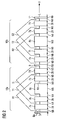
- FIG. 2 is a section of the stator 5 shown in the form of a schematic sectional view.
- the section of the upright 5 is not in the form of a circular arc, as in reality, but rolled up on a plane, shown schematically.
- Coil groups are arranged along the circumference of the stator 5, the coil groups each having at least three coils.
- a first coil groups 10a which consists of the three coils R1, T1 and S1
- a second coil group 10b which consists of the three coils R2, T2 and S2, shown.
- the coils are shown only symbolically.
- the second coil group 10b is arranged in the circumferential direction U of the stator directly after the first coil group 10a.
- the grooves 6a and 6d provided with a reference numeral, wherein all the grooves of the stator have the same groove width NB, ie a uniform groove width NB.
- the first coil group 10a has the coils R1, T1 and S1 and the second coil group 10b has the coils R2, T2 and S2 in the exemplary embodiment.
- the coil R1 extends, as indicated by the symbol of the coil R1, in the grooves 6a and 6d and thus encloses the teeth 7a, 7b and 8a. Accordingly, the remaining coils in the grooves associated with the respective coils pass as shown by the symbols of the coils.
- the phase current R flows through the coils R1 and R2, the phase current T flows through the coils T1 and T2, and the phase current S flows through the coils S1 and S2.
- the coil groups are arranged along the circumference of the stator.
- the coil groups each have three coils. This need not necessarily be so, but a coil group may also have more than three coils.
- the coil groups also respectively have six coils, in which case through the first two directly following in the circumferential direction U coils of the phase current R flows through the next two directly in the circumferential direction U successive coils of the phase current T flows and through the next two in the circumferential direction U directly successive coils of the phase current S flows, so that a total of three-phase three-phase system again arises.
- the first coil group 10a is associated with the teeth 7a, 7b, 8a, 7c, 7d and the tooth 9.
- the second coil group 10b, the teeth 7e, 7f, 8b, 7g, 7b and 11 are assigned.
- the teeth, which are arranged in the middle of the coil groups are hereinafter referred to as center teeth and the teeth which are arranged between two directly in the circumferential direction U successive groups of coils are hereinafter referred to as peripheral teeth.
- the first center tooth 8a is disposed at the center of the first coil group 10a
- the second center tooth 8b is disposed at the center of the second coil group 10b.
- the first edge tooth 9 is disposed between the first coil group 10a and the second coil group 10b.
- the second coil group 10b is arranged in direct succession after the first coil group 10a.
- the second edge tooth 11 is between the second coil group 10b and one in FIG. 2 Arranged not shown third coil group.
- the teeth which are not arranged in the middle of a coil group and not between two in the circumferential direction of the stator directly successively arranged coil groups, all have the same tooth width ZB, ie a uniform tooth width ZB.
- these are the teeth 7a, 7b, 7c, 7d, 7e, 7f, 7g and 7h.
- the teeth 7a, 7b, 7c, 7d, 7e, 7f, 7g and 7h have a uniform tooth width ZB.
- all the grooves have the same groove width NB, ie a uniform groove width NB.
- the first center tooth 8a has a first center tooth width MB and the first edge tooth 9 has a first edge tooth width RB.
- the respective center tooth has the same center tooth width MB for all coil groups, i. a uniform center tooth width MB.
- all edge teeth have the same edge tooth width RB, i. a uniform edge tooth width RB.
- the groove pitch width is changed in order to reduce the latching and / or pendulum moments by the width of the tooth, which is arranged between two circumferentially directly successively arranged coil groups, is reduced by a factor a and corresponding to the factor a, the width of the tooth, which is arranged in the middle of the coil group is assigned to the edge tooth, is increased.
- the first edge tooth width RB of the first edge tooth 9 is thus reduced with respect to the tooth width ZB and, corresponding to the reduction, the first center tooth width MB of the first center tooth 8a is increased.
- the following applies to the first edge tooth width RB: RB a ⁇
- RB 2 - a ⁇
- the factor a is greater than 0 and not more than 0.35.
- the tooth width ZB corresponds to the length of the circular arc over the angle ⁇ 1
- the groove width NB corresponds to the length of the circular arc over the angle ⁇ 2
- the first center tooth width MB corresponds to the length of the arc over the angle ⁇ 3
- the first edge tooth width RB corresponds to Length of the arc above the angle ⁇ 4 (see FIG. 1 )
- r is the radius of the stator.
- the radius r of the stator goes from the axis of rotation R to that of the rotor 2 zugewanden side of the teeth (see FIG. 1 ).
- the respective angle is the angle which is spanned by the edges of the rotor 2 facing the side of the respective associated teeth, starting from the axis of rotation R, in the axial direction Z (see FIG FIG. 1 ).
- the rotor 2 facing side of the first center tooth 8a is in FIG. 1 provided with the reference numeral 13 and extending in the axial direction Z edges of the rotor 2 zugewanden side 11 of the first central tooth 8a are in FIG. 1 provided with the reference numerals 12a and 12b.
- the width of the coil is not changed.
- the distance between the coils within a coil group is also the same.
- the groove width NB is chosen so that the coils fit into the grooves.
- the edge tooth widths and the center tooth widths in the other coil groups are carried out correspondingly, as for the first coil group 10a, the factor a being identical for all coil groups.
- the center tooth width of the second center tooth 8b is thus the same as the center tooth width of the first center tooth 8a, and the edge tooth width of the second edge tooth 11 is thus the same size as the edge tooth width of the first edge tooth 9.
- the value of the factor a may also be different for the coil groups.
- the factor a in the first coil group 10a is 0.1 and in the second coil group 10b is 0.2, so that the widths of the central teeth 8a and 8b and the widths of the peripheral teeth 9 and 11 are different.
Landscapes
- Engineering & Computer Science (AREA)
- Power Engineering (AREA)
- Iron Core Of Rotating Electric Machines (AREA)
- Permanent Magnet Type Synchronous Machine (AREA)
- Synchronous Machinery (AREA)
Description
- Die Erfindung betrifft einen Ständer einer permanenterregten rotierenden elektrischen Maschine.
- Bei einer permanenterregten rotierenden elektrischen Maschine, wie z.B. einem permanenterregten Generator oder einem permanenterregten Elektromotor, sind insbesondere die Rastmomente im Stillstand der elektrischen Maschine eine kritische Designgröße. Die Amplitude der Rastmomente muss dabei möglichst minimal sein. Darüber hinaus sind auch die Pendelmomente, die unter Last auftreten, möglichst gering zu halten.
- Insbesondere bei direkt angetriebenen, permanenterregten Windkraftgeneratoren sind die Rastmomente, die im Stillstand auftreten, sowie die Pendelmomente, die im Betrieb des Windkraftgenerators auftreten, möglichst gering zu halten.
- Zur Minimierung der Pendelmomente werden heute im Wesentlichen folgende Verfahren angewendet:
- Schrägung der im Rotor der elektrischen Maschine angeordneten Permanentmagnete,
- Schrägung der elektrischen Leiter im Ständer der elektrischen Maschine,
- Versetzen der Permanentmagnete des Rotors aus der Polmitte.
- Die oben genannten bekannten Verfahren sind jedoch fertigungstechnisch aufwändig.
- Insbesondere bei elektrischen Großmaschinen wird der Ständer üblicherweise mit sogenannten Zweischichtwicklungen, in seltenen Fällen auch mit Einschichtwicklungen, ausgerüstet. Um dabei Spulen gleicher Breite realisieren zu können, wird handelsüblich, insbesondere bei Zweischichtwicklungen, die Breite der Zähne und Nuten derart realisiert, dass sich eine gleichmäßige Nutteilungsbreite über den Umfang des Ständers ergibt, wobei alle Zähne und Nuten eine einheitliche Breite aufweisen. Bei Einschichtwicklungen mit drei Etagen oder mit Faßspulen wird durch die Anordnung der Spulen einer Spulengruppe dagegen jeweils pro Spulengruppe eine sogenannte doppelte Polteilung realisiert, so dass sich pro Spulengruppe ein sogenanntes Polpaar ergibt. Nach jeder Spulengruppe befindet sich ein Bereich am Umfang des Ständers, in dem keine Spulen angeordnet sind. Diese Eigentümlichkeit der Anordnung kann genutzt werden, um die Nutteilbreite über dem Umfang des Ständers zu variieren, ohne dass dabei die Breite der Spulen unterschiedlich sein muss. Dies kann genutzt werden, um auftretende Rast- und Pendelmomente zu vermindern und die Form der Feldkurve (Wicklungsfaktor) zu verbessern.
-
DE 10 2008 032 314 A1 ist Stand der Technik. - Es ist Aufgabe der Erfindung, bei einer permanenterregten rotierenden elektrischen Maschine auftretende Rast- und/oder Pendelmomente zu verringern.
- Diese Aufgabe wird erfindungsgemäß gelöst durch einen Ständer einer permanenterregten rotierenden elektrischen Maschine, wobei der Ständer mehrere in axialer Richtung des Ständers verlaufende Zähne und Nuten aufweist, wobei entlang dem Umfang des Ständers Spulengruppen angeordnet sind, wobei die Spulengruppen jeweilig mindestens drei Spulen aufweisen, die in Umfangsrichtung in direkt aufeinander folgend angeordneten Nuten angeordnet sind, wobei alle Nuten eine einheitliche Nutbreite NB aufweisen, wobei die Zähne, die nicht in der Mitte einer Spulengruppe und nicht zwischen zwei in Umfangsrichtung des Ständers direkt aufeinander folgend angeordneten Spulengruppen angeordnet sind eine einheitliche Zahnbreite ZB aufweisen, wobei in der Mitte einer ersten Spulengruppe ein erster Mittenzahn, der eine erste Mittenzahnbreite MB aufweist, angeordnet ist, wobei der Ständer eine zweite Spulengruppe aufweist, wobei die erste und die zweite Spulengruppe in Umfangsrichtung direkt aufeinander folgend angeordnet sind, wobei zwischen der ersten und der zweiten Spulengruppe ein erster Randzahn, der eine erste Randzahnbreite RB aufweist, angeordnet ist, wobei die erste Randzahnbereite RB im Wesentlichen

ist und die erste Mittenzahnbreite MB im Wesentlichen MB = (2-a) ·ZB ist,
wobei der Faktor a größer als 0 ist und maximal 0,35 ist. - Wenn der Faktor a größer als 0 ist und maximal 0,35 ist, werden die Rast- und/oder Pendelmomente besonders stark vermindert.
- Vorteilhafte Ausbildungen der Erfindung ergeben sich aus den abhängigen Ansprüchen.
- Weiterhin erweist es sich als vorteilhaft, wenn entsprechend wie für die erste Spulengruppe die Randzahnbreiten und die Mittenzahnbreiten bei den übrigen Spulengruppen ausgeführt sind, wobei der Faktor a bei allen Spulengruppen identisch ist oder der Faktor a bei mindestens zwei Spulengruppen unterschiedlich ist. Wenn der Faktor a bei allen Spulengruppen identisch ist, ergibt sich eine sehr symmetrische Gesamtanordnung und die Rast- und/oder Pendelmomente werden besonders stark vermindert. Wenn der Faktor a uneinheitlich ist, kann der Ständer besonders einfach gefertigt werden.
- Die permanenterregte rotierende elektrische Maschine kann dabei z.B. als Generator oder Elektromotor ausgebildet sein, wobei der Generator insbesondere als Windkraftgenerator und insbesondere als direkt angetriebener (das Windrad ist direkt ohne zwischengeschaltetes Getriebe mit dem Windkraftgenerator verbunden) Windkraftgenerator ausgebildet sein kann.
- Ein Ausführungsbeispiel der Erfindung ist in der Zeichnung dargestellt und wird im Folgenden näher erläutert. Dabei zeigen:
- FIG 1
- eine schematisierte Ansicht einer erfindungsgemäßen permanenterregten rotierenden elektrischen Maschine und
- FIG 2
- eine schematisierte Detailansicht eines Ausschnitts eines erfindungsgemäßen Ständers der Maschine.
- In
FIG 1 ist in Form einer schematisierten perspektivischen Darstellung eine erfindungsgemäße permanenterregte rotierende elektrische Maschine 1 dargestellt. Die Maschine 1 ist dabei im Rahmen des Ausführungsbeispiels als Generator und insbesondere als Windkraftgenerator ausgebildet. Es sei dabei an dieser Stelle angemerkt, dass der Übersichtlichkeit halber inFIG 1 nur die zum Verständnis der Erfindung wesentlichen Elemente der Maschine 1 dargestellt sind. - Die Maschine 1 weist einen Rotor 2 auf, der rotierbar um eine Rotationsachse R der Maschine 1 angeordnet ist. Der Rotor 2 umfasst dabei alle um die Rotorachse R rotierbar angeordneten Elemente der Maschine 1. Der Rotor 2 weist ein Rotorjoch 3 auf, an dem Permanentmagnete angeordnet sind, wobei der Übersichtlichkeit halber in
FIG 1 nur ein Permanentmagnet 4 mit einem Bezugszeichen versehen ist. Im Betrieb der Maschine 1 rotiert der Rotor 2 im Rahmen des Ausführungsbeispiels um einen in der Maschine 1 zentral angeordneten und gegenüber der Umgebung der Maschine 1 ruhend angeordneten Ständer 5. Da der Rotor 2 um den Ständer 5 herum angeordnet ist, wird eine solche Maschine fachspezifisch auch als Außenläufer bezeichnet. Da der Rotor 1 Permanentmagnete aufweist, welche permanent ein Magnetfeld zum Betrieb der Maschine 1 erzeugen, wird eine solche Maschine fachspezifisch auch als permanenterregte oder permanetmagneterregte Maschine bezeichnet. Da die Maschine 1 einen um eine Rotationsachse R im Betrieb der Maschine 1 rotierenden Rotor 2 aufweist, wird eine solche Maschine auch als rotierende elektrische Maschine bezeichnet. - Der Ständer 5 weist mehrere in axialer Richtung Z verlaufende Zähne und Nuten auf, wobei der Übersichtlichkeit halber in
FIG 1 nur die Zähne 7a, 8a und 9 und die Nut 6a mit einem Bezugszeichen versehen sind. Der Ständer besteht dabei im Rahmen des Ausführungsbeispiels aus in axialer Richtung Z hintereinander angeordneten Blechen. Die einzelnen Bleche sind dabei in der Regel mit einer elektrischen Isolierschicht, wie z.B. einer Lackschicht, versehen. - Die Zähne und Nuten der Segmente entstehen durch eine entsprechende Ausbildung der Form der Bleche. In den Nuten um die Zähne herum verlaufen die elektrischen Spulen des Ständers, wobei die Spulen der Übersichtlichkeit halber und da für das Verständnis der Erfindung unwesentlich, nicht dargestellt sind.
- Bei handelsüblichen permanenterregten rotierenden elektrischen Maschinen sind dabei die Breiten der einzelnen Zähne des Ständers 5 alle gleich. Erfindungsgemäß werden durch eine gezielte Vergrößerung und Verkleinerung der Breite bestimmter Zähne gegenüber den restlichen Zähnen des Ständers beim Betrieb der Maschine 1 auftretende Rast- und Pendelmomente verringert.
- Es sei an dieser Stelle noch einmal angemerkt, dass es sich bei der
FIG 1 um eine schematisierte Darstellung handelt, bei der z.B. insbesondere die Breite, Anzahl und Abmessungen der Zähne, Nuten und Permanentmagnete, sowie die Größe des zwischen Ständer und Rotor angeordneten Luftspalts nicht mit der Realität übereinstimmen. - In
FIG 2 ist in Form einer schematisierten Schnittansicht ein Ausschnitt des Ständers 5 dargestellt. Der Übersichtlichkeit halber ist der Ausschnitt des Ständers 5 dabei nicht wie in der Realität kreisbogenförmig, sondern auf einer Ebene aufgerollt, schematisiert dargestellt. - Entlang dem Umfang des Ständers 5 sind Spulengruppen angeordnet, wobei die Spulengruppe jeweils mindestens drei Spulen aufweisen. In
FIG 2 ist dabei eine erste Spulengruppen 10a, die aus den drei Spulen R1, T1 und S1 besteht, und eine zweite Spulengruppe 10b, die aus den drei Spulen R2, T2 und S2 besteht, dargestellt. Die Spulen sind dabei nur symbolhaft dargestellt. Die zweite Spulengruppe 10b ist in Umfangsrichtung U des Ständers direkt nach der ersten Spulengruppe 10a angeordnet. Der Übersichtlichkeit halber sind in derFIG 2 nur die Nuten 6a und 6d mit einem Bezugszeichen versehen, wobei alle Nuten des Ständers die gleiche Nutbreite NB, d.h. eine einheitliche Nutbreite NB aufweisen. - Die erste Spulengruppe 10a weist im Rahmen des Ausführungsbeispiels, wie schon gesagt, die Spulen R1, T1 und S1 und die zweite Spulengruppe 10b die Spulen R2, T2 und S2 auf. Die Spule R1 verläuft dabei, wie durch das Symbol der Spule R1 angedeutet, in den Nuten 6a und 6d und umschließt somit die Zähne 7a, 7b und 8a. Entsprechend verlaufen die übrigen Spulen in den, den jeweiligen Spulen zugehörigen Nuten, wie von den Symbolen der Spulen dargestellt. Durch die Spulen R1 und R2 fließt der Phasenstrom R, durch die Spulen T1 und T2 fließt der Phasenstrom T und durch die Spulen S1 und S2 der Phasenstrom S. Die Spulengruppen sind dabei entlang dem Umfang des Ständers angeordnet. Wie bereits erläutert, weisen im Rahmen des Ausführungsbeispiels, die Spulengruppen dabei jeweils drei Spulen auf. Dies muss nicht notwendigerweise so sein, sondern eine Spulengruppe kann auch mehr wie drei Spulen aufweisen. So können z.B. die Spulengruppen auch jeweilig sechs Spulen aufweisen, wobei in diesem Fall dann durch die ersten zwei direkt aufeinander in Umfangsrichtung U folgenden Spulen der Phasenstrom R fließt durch die nächsten zwei direkt in Umfangsrichtung U aufeinander folgenden Spulen der Phasenstrom T fließt und durch die nächsten zwei in Umfangsrichtung U direkt aufeinander folgenden Spulen der Phasenstrom S fließt, so dass insgesamt wieder ein dreiphasiges Drehstromsystem entsteht.
- Der ersten Spulengruppe 10a sind die Zähne 7a, 7b, 8a, 7c, 7d und der Zahn 9 zugeordnet. Der zweiten Spulengruppe 10b sind die Zähne 7e, 7f, 8b, 7g, 7b und 11 zugeordnet. Die Zähne, die in der Mitte der Spulengruppen angeordnet sind, werden nachfolgend als Mittenzähne bezeichnet und die Zähne, welche zwischen zwei direkt in Umfangsrichtung U aufeinander folgenden Spulengruppen angeordnet sind, werden nachfolgend als Randzähne bezeichnet. Der erste Mittenzahn 8a ist in der Mitte der ersten Spulengruppe 10a angeordnet und der zweite Mittenzahn 8b ist in der Mitte der zweiten Spulengruppe 10b angeordnet. Der erste Randzahn 9 ist zwischen der ersten Spulengruppe 10a und der zweiten Spulengruppe 10b angeordnet. In Umfangsrichtung U des Ständers ist nach der ersten Spulengruppe 10a direkt aufeinanderfolgend die zweite Spulengruppe 10b angeordnet.
- Der zweite Randzahn 11 ist zwischen der zweiten Spulengruppe 10b und einer in
FIG 2 nicht mehr dargestellten dritten Spulengruppe angeordnet. Die Zähne, die nicht in der Mitte einer Spulengruppe und nicht zwischen zwei in Umfangsrichtung des Ständers direkt aufeinander folgend angeordneten Spulengruppen angeordnet sind, weisen alle die gleiche Zahnbreite ZB, d.h. eine einheitliche Zahnbreite ZB auf. Im Rahmen des Ausführungsbeispiels sind dies die Zähne 7a, 7b, 7c, 7d, 7e, 7f, 7g und 7h. Die Zähne 7a, 7b, 7c, 7d, 7e, 7f, 7g und 7h weisen eine einheitliche Zahnbreite ZB auf. Wie bereits erläutert, weisen alle Nuten die gleiche Nutbreite NB auf, d.h. eine einheitliche Nutbreite NB auf. Der erste Mittenzahn 8a weist eine erste Mittenzahnbreite MB auf und der erste Randzahn 9 eine erste Randzahnbreite RB. - Im Rahmen des Ausführungsbeispiels weist dabei der jeweilige Mittenzahn bei allen Spulengruppen die gleiche Mittenzahnbreite MB, d.h. eine einheitliche Mittenzahnbreite MB auf. Weiterhin weisen alle Randzähne die gleiche Randzahnbreite RB, d.h. eine einheitliche Randzahnbreite RB auf.
- Bei einem handelsüblichen Ständer einer permanenterregten rotierenden elektrischen Maschine weisen alle Zähne und alle Nuten eine einheitliche Breite auf. Das heißt, die so genannte Nutteilungsbreite NTB, die die Summe der Breite eines Zahns und der Breite der den Zahn direkt nachfolgenden Nut ist, ergibt bei einem handelsüblichen Ständer zu:

wobei N die Anzahl der Nuten, U der Umfang des Ständers und r der Radius des Ständers ist. - Erfindungsgemäß wird zur Verringerung der Rast- und/oder Pendelmomente die Nutteilungsbreite verändert, indem die Breite des Zahns, der zwischen zwei in Umfangsrichtung direkt aufeinander folgend angeordneten Spulengruppen angeordnet ist, um einen Faktor a verkleinert wird und entsprechend dem Faktor a die Breite des Zahns, der in der Mitte der Spulengruppe angeordnet ist zu dem der Randzahn zugeordnet ist, vergrößert wird. Die erste Randzahnbreite RB des ersten Randzahns 9 wird somit gegenüber der Zahnbreite ZB verkleinert und entsprechend der Verkleinerung wird die erste Mittenzahnbreite MB des ersten Mittenzahns 8a vergrößert. Für die erste Randzahnbreite RB gilt somit:

und für die erste Mittenzahnbreite MB gilt:
wobei der Faktor a größer als 0 und maximal 0,35 ist. Die Zahnbreite ZB entspricht dabei der Länge des Kreisbogens über dem Winkel α1, die Nutbreite NB entspricht der Länge des Kreisbogens über dem Winkel α2, die erste Mittenzahnbreite MB entspricht der Länge des Kreisbogens über dem Winkel α3 und die erste Randzahnbreite RB entspricht der Länge des Kreisbogens über dem Winkel α4 (sieheFIG 1 ), - Es gilt somit:


wobei r der Radius des Ständers ist. Der Radius r des Ständers geht dabei von der Rotationsachse R bis zur der dem Rotor 2 zugewanden Seite der Zähne (sieheFIG 1 ). Der jeweilige Winkel ist der Winkel, der von den in axialer Richtung Z verlaufenden Kanten der dem Rotor 2 zugewanden Seite der jeweilig zugehörigen Zähne, ausgehend von der Rotationsachse R, aufgespannt wird (sieheFIG 1 ). Die dem Rotor 2 zugewande Seite des ersten Mittenzahns 8a ist inFIG 1 mit dem Bezugszeichen 13 versehen und die in axialer Richtung Z verlaufenden Kanten der dem Rotor 2 zugewanden Seite 11 des ersten Mittenzahns 8a sind inFIG 1 mit den Bezugszeichen 12a und 12b versehen. - Durch die erfindungsgemäße Verkleinerung der Breite des Randzahns und entsprechende Vergrößerung der Breite des Mittenzahns wird die Breite der Spulen nicht geändert. Der Abstand zwischen den Spulen innerhalb einer Spulengruppe ist ebenfalls gleich. Es ergibt sich somit weiterhin wie beim handelsüblichen Ständer ein symmetrisches dreiphasiges Drehstromsystem.
- Die Nutbreite NB wird dabei so gewählt, dass die Spulen in die Nuten passen.
- Im Rahmen des Ausführungsbeispiels sind dabei, entsprechend wie für die erste Spulengruppe 10a, die Randzahnbreiten und die Mittenzahnbreiten bei den übrigen Spulengruppen ausgeführt, wobei der Faktor a bei allen Spulengruppen identisch ist. Die Mittenzahnbreite des zweiten Mittenzahns 8b ist somit genauso groß wie die Mittenzahnbreite des ersten Mittenzahns 8a und die Randzahnbreite des zweiten Randzahns 11 ist somit genauso groß wie die Randzahnbreite des ersten Randzahns 9.
- Alternativ hierzu kann der Wert des Faktors a aber auch bei den Spulengruppen unterschiedlich sein. So kann z.B. der Faktor a bei der ersten Spulengruppe 10a 0,1 betragen und bei der zweiten Spulengruppe 10b 0,2, so dass sich für die Breiten der Mittenzähne 8a und 8b und die Breiten der Randzähne 9 und 11 unterschiedliche Werte ergeben.
Claims (4)
- Ständer einer permanenterregten rotierenden elektrischen Maschine (1), wobei der Ständer (5) mehrere in axialer Richtung (Z) des Ständers (5) verlaufende Zähne (7a,8a, 9) und Nuten (6a, 6d) aufweist, wobei entlang dem Umfang des Ständers (5) Spulengruppen (10a,10b) angeordnet sind, wobei alle Nuten eine einheitliche Nutbreite NB aufweisen,
dadurch gekennzeichnet,
dass die Spulengruppen (10a,10b) jeweilig mindestens drei Spulen (R1,T1,S1) aufweisen, die in Umfangsrichtung (U) in direkt aufeinander folgend angeordneten Nuten angeordnet sind, wobei die Zähne, die nicht in der Mitte einer Spulengruppe (10a,10b) und nicht zwischen zwei in Umfangsrichtung (U) des Ständers (5) direkt aufeinander folgend angeordneten Spulengruppen (10a,10b) angeordnet sind eine einheitliche Zahnbreite ZB aufweisen, wobei in der Mitte einer ersten Spulengruppe (10a) ein erster Mittenzahn (8a), der eine erste Mittenzahnbreite MB aufweist, angeordnet ist, wobei der Ständer (5) eine zweite Spulengruppe (10b) aufweist, wobei die erste und die zweite Spulengruppe in Umfangsrichtung (U) direkt aufeinander folgend angeordnet sind, wobei zwischen der ersten und der zweiten Spulengruppe ein erster Randzahn (9), der eine erste Randzahnbreite RB aufweist, angeordnet ist, wobei die erste Randzahnbereite RB im Wesentlichen
ist und die erste Mittenzahnbreite MB im Wesentlichen
wobei der Faktor a größer als 0 ist und maximal 0,35 ist. - Ständer nach Anspruch 1,
dadurch gekennzeichnet, dass entsprechend wie für die erste Spulengruppe (10a) die Randzahnbreiten und die Mittenzahnbreiten bei den übrigen Spulengruppen ausgeführt sind, wobei der Faktor a bei allen Spulengruppen identisch ist oder der Faktor a bei mindestens zwei Spulengruppen unterschiedlich ist. - Permanenterregte rotierende elektrische Maschine, wobei die Maschine als Generator oder Elektromotor ausgebildet ist und einen Ständer nach einem der vorhergehenden Ansprüche aufweist.
- Permanenterregte rotierende elektrische Maschine nach Anspruch 3, dadurch gekennzeichnet, dass der Generator als Windkraftgenerator ausgebildet ist.
Applications Claiming Priority (2)
| Application Number | Priority Date | Filing Date | Title |
|---|---|---|---|
| DE102010001619A DE102010001619A1 (de) | 2010-02-05 | 2010-02-05 | Ständer einer permanenterregten rotierenden elektrischen Maschine |
| PCT/EP2010/070929 WO2011095266A2 (de) | 2010-02-05 | 2010-12-30 | Ständer einer permanenterregten rotierenden elektrischen maschine |
Publications (2)
| Publication Number | Publication Date |
|---|---|
| EP2532074A2 EP2532074A2 (de) | 2012-12-12 |
| EP2532074B1 true EP2532074B1 (de) | 2014-03-19 |
Family
ID=44303238
Family Applications (1)
| Application Number | Title | Priority Date | Filing Date |
|---|---|---|---|
| EP10798826.3A Not-in-force EP2532074B1 (de) | 2010-02-05 | 2010-12-30 | Ständer einer permanenterregten rotierenden elektrischen maschine |
Country Status (12)
| Country | Link |
|---|---|
| US (1) | US20120299433A1 (de) |
| EP (1) | EP2532074B1 (de) |
| JP (1) | JP2013519348A (de) |
| KR (1) | KR20120124433A (de) |
| CN (1) | CN102906965A (de) |
| BR (1) | BR112012019411A2 (de) |
| CA (1) | CA2789036A1 (de) |
| DE (1) | DE102010001619A1 (de) |
| DK (1) | DK2532074T3 (de) |
| ES (1) | ES2454768T3 (de) |
| RU (1) | RU2516246C2 (de) |
| WO (1) | WO2011095266A2 (de) |
Families Citing this family (1)
| Publication number | Priority date | Publication date | Assignee | Title |
|---|---|---|---|---|
| DE102023208847B4 (de) * | 2023-09-12 | 2025-04-03 | Zf Friedrichshafen Ag | Wicklung, Komponente für eine elektrische Maschine, elektrische Maschine und Kraftfahrzeug und Verfahren zum Herstellen einer Wicklung |
Family Cites Families (17)
| Publication number | Priority date | Publication date | Assignee | Title |
|---|---|---|---|---|
| US2506637A (en) * | 1945-04-28 | 1950-05-09 | Wagner Electric Corp | Electromagnetic core construction |
| DE1196290B (de) * | 1959-12-19 | 1965-07-08 | Himmelwerk A G | Ein- oder Mehrphasenmaschine mit unterschiedlichen Nutenteilungen |
| JPS58108939A (ja) * | 1982-01-29 | 1983-06-29 | Sawafuji Electric Co Ltd | 回転電機用円筒形回転子 |
| US4692646A (en) * | 1984-08-01 | 1987-09-08 | Matsushita Electric Industrial Co., Ltd. | Rotating electric motor with reduced cogging torque |
| JPS61221556A (ja) * | 1985-03-25 | 1986-10-01 | Matsushita Electric Ind Co Ltd | 発電機 |
| CN1008419B (zh) * | 1985-08-06 | 1990-06-13 | 松下电器产业株式会社 | 减小齿槽效应转矩的旋转电机 |
| JPH0721078Y2 (ja) * | 1988-07-21 | 1995-05-15 | 多摩川精機株式会社 | 電動機 |
| JPH0284044A (ja) * | 1988-09-16 | 1990-03-26 | Koufu Meidensha:Kk | ブラシレスdcモータ |
| JPH04285444A (ja) * | 1991-03-12 | 1992-10-09 | Fujitsu General Ltd | 電動機の固定子鉄心 |
| DE10124415A1 (de) * | 2001-05-18 | 2002-11-28 | Siemens Ag | Elektrische Maschine |
| DE10248771A1 (de) * | 2002-10-18 | 2004-04-29 | Siemens Ag | Permanenterregte Synchronmaschine |
| US7081697B2 (en) * | 2004-06-16 | 2006-07-25 | Visteon Global Technologies, Inc. | Dynamoelectric machine stator core with mini caps |
| US7608965B2 (en) * | 2005-09-01 | 2009-10-27 | Wisconsin Alumni Research Foundation | Field controlled axial flux permanent magnet electrical machine |
| DE102006002900B4 (de) * | 2006-01-20 | 2007-12-20 | Siemens Ag | Elektrische Maschine mit einem dreisträngigen Wicklungssystem |
| CN201057630Y (zh) * | 2007-06-06 | 2008-05-07 | 上海特波电机有限公司 | 不等宽结构的低波动永磁无刷电机 |
| US8093737B2 (en) * | 2008-05-29 | 2012-01-10 | General Electric Company | Method for increasing energy capture in a wind turbine |
| DE102008064678A1 (de) * | 2008-07-09 | 2011-03-10 | Siemens Aktiengesellschaft | Dynamoelektrische Maschine mit Zahnspulen-Wicklung im Stator |
-
2010
- 2010-02-05 DE DE102010001619A patent/DE102010001619A1/de not_active Withdrawn
- 2010-12-30 RU RU2012137788/07A patent/RU2516246C2/ru not_active IP Right Cessation
- 2010-12-30 US US13/576,859 patent/US20120299433A1/en not_active Abandoned
- 2010-12-30 JP JP2012551528A patent/JP2013519348A/ja not_active Withdrawn
- 2010-12-30 EP EP10798826.3A patent/EP2532074B1/de not_active Not-in-force
- 2010-12-30 BR BR112012019411A patent/BR112012019411A2/pt not_active IP Right Cessation
- 2010-12-30 CN CN2010800626157A patent/CN102906965A/zh active Pending
- 2010-12-30 CA CA2789036A patent/CA2789036A1/en not_active Abandoned
- 2010-12-30 KR KR1020127020463A patent/KR20120124433A/ko not_active Withdrawn
- 2010-12-30 ES ES10798826.3T patent/ES2454768T3/es active Active
- 2010-12-30 DK DK10798826.3T patent/DK2532074T3/da active
- 2010-12-30 WO PCT/EP2010/070929 patent/WO2011095266A2/de not_active Ceased
Also Published As
| Publication number | Publication date |
|---|---|
| DK2532074T3 (da) | 2014-06-02 |
| WO2011095266A3 (de) | 2011-10-13 |
| RU2516246C2 (ru) | 2014-05-20 |
| CA2789036A1 (en) | 2011-08-11 |
| ES2454768T3 (es) | 2014-04-11 |
| DE102010001619A1 (de) | 2011-08-11 |
| US20120299433A1 (en) | 2012-11-29 |
| EP2532074A2 (de) | 2012-12-12 |
| RU2012137788A (ru) | 2014-03-10 |
| BR112012019411A2 (pt) | 2018-03-20 |
| JP2013519348A (ja) | 2013-05-23 |
| CN102906965A (zh) | 2013-01-30 |
| KR20120124433A (ko) | 2012-11-13 |
| WO2011095266A2 (de) | 2011-08-11 |
Similar Documents
| Publication | Publication Date | Title |
|---|---|---|
| EP2639936B1 (de) | Elektrische Maschine mit permanent erregtem Läufer und zugehöriger permanent erregter Läufer | |
| EP2494678B1 (de) | Elektrische antriebsmaschine für ein fahrzeug | |
| DE102007007578B4 (de) | Elektrische Maschine | |
| EP3038233B1 (de) | Permanentmagnet-synchronmotor und elektrische servolenkung | |
| EP2427951B1 (de) | Elektrische synchronmaschine | |
| DE102010010127A1 (de) | Optimierte elektrische Maschine für intelligente Stellglieder | |
| EP2160816A2 (de) | Synchronmotor mit 12 statorzähnen und 10 rotorpolen | |
| WO2010088983A1 (de) | Synchronmaschine | |
| WO2018095903A1 (de) | Synchron-maschine mit magnetischer drehfelduntersetzung und flusskonzentration | |
| WO2018002128A1 (de) | Rotor, verfahren zum herstellen eines rotors, reluktanzmaschine und arbeitsmaschine | |
| EP2532073B1 (de) | Ständer einer permanenterregten rotierenden elektrischen maschine | |
| DE102008032314A1 (de) | Dynamoelektrische Maschine mit Zahnspulen-Wicklung im Stator | |
| DE102012213465A1 (de) | Permanentmagnet-Synchronmotor und Servolenkungsanordnung | |
| EP3758194B1 (de) | Rotor für eine elektrische maschine, elektrische maschine für ein fahrzeug und fahrzeug | |
| EP2532074B1 (de) | Ständer einer permanenterregten rotierenden elektrischen maschine | |
| DE102011055766A1 (de) | Drehstrom-Synchronmaschine | |
| WO2020177964A1 (de) | Rotor für eine permanenterregte elektrische maschine mit stützstruktur | |
| EP4487454A1 (de) | Elektromotor und zugehörige verwendung | |
| EP3457533B1 (de) | Rotor einer elektrischen maschine | |
| EP2681827B1 (de) | Elektrische maschine mit einem rotor mit reduziertem rastmoment | |
| DE102024102766A1 (de) | Elektrische maschine für ein kraftfahrzeug | |
| DE102022102313A1 (de) | Stator und elektrische Maschine | |
| DE102016221416A1 (de) | Elektrische Maschine | |
| WO2024217707A1 (de) | Rotorblech, elektrische maschine, elektrischer achsantrieb und kraftfahrzeug |
Legal Events
| Date | Code | Title | Description |
|---|---|---|---|
| PUAI | Public reference made under article 153(3) epc to a published international application that has entered the european phase |
Free format text: ORIGINAL CODE: 0009012 |
|
| 17P | Request for examination filed |
Effective date: 20120726 |
|
| AK | Designated contracting states |
Kind code of ref document: A2 Designated state(s): AL AT BE BG CH CY CZ DE DK EE ES FI FR GB GR HR HU IE IS IT LI LT LU LV MC MK MT NL NO PL PT RO RS SE SI SK SM TR |
|
| RAP1 | Party data changed (applicant data changed or rights of an application transferred) |
Owner name: SIEMENS AKTIENGESELLSCHAFT |
|
| DAX | Request for extension of the european patent (deleted) | ||
| GRAP | Despatch of communication of intention to grant a patent |
Free format text: ORIGINAL CODE: EPIDOSNIGR1 |
|
| INTG | Intention to grant announced |
Effective date: 20131011 |
|
| GRAS | Grant fee paid |
Free format text: ORIGINAL CODE: EPIDOSNIGR3 |
|
| GRAA | (expected) grant |
Free format text: ORIGINAL CODE: 0009210 |
|
| AK | Designated contracting states |
Kind code of ref document: B1 Designated state(s): AL AT BE BG CH CY CZ DE DK EE ES FI FR GB GR HR HU IE IS IT LI LT LU LV MC MK MT NL NO PL PT RO RS SE SI SK SM TR |
|
| REG | Reference to a national code |
Ref country code: GB Ref legal event code: FG4D Free format text: NOT ENGLISH |
|
| REG | Reference to a national code |
Ref country code: CH Ref legal event code: EP |
|
| REG | Reference to a national code |
Ref country code: ES Ref legal event code: FG2A Ref document number: 2454768 Country of ref document: ES Kind code of ref document: T3 Effective date: 20140411 |
|
| REG | Reference to a national code |
Ref country code: AT Ref legal event code: REF Ref document number: 658233 Country of ref document: AT Kind code of ref document: T Effective date: 20140415 |
|
| REG | Reference to a national code |
Ref country code: IE Ref legal event code: FG4D Free format text: LANGUAGE OF EP DOCUMENT: GERMAN |
|
| REG | Reference to a national code |
Ref country code: DE Ref legal event code: R096 Ref document number: 502010006445 Country of ref document: DE Effective date: 20140430 |
|
| REG | Reference to a national code |
Ref country code: NL Ref legal event code: T3 |
|
| REG | Reference to a national code |
Ref country code: DK Ref legal event code: T3 Effective date: 20140526 |
|
| PG25 | Lapsed in a contracting state [announced via postgrant information from national office to epo] |
Ref country code: LT Free format text: LAPSE BECAUSE OF FAILURE TO SUBMIT A TRANSLATION OF THE DESCRIPTION OR TO PAY THE FEE WITHIN THE PRESCRIBED TIME-LIMIT Effective date: 20140319 |
|
| REG | Reference to a national code |
Ref country code: NO Ref legal event code: T2 Effective date: 20140319 Ref country code: LT Ref legal event code: MG4D |
|
| PG25 | Lapsed in a contracting state [announced via postgrant information from national office to epo] |
Ref country code: SE Free format text: LAPSE BECAUSE OF FAILURE TO SUBMIT A TRANSLATION OF THE DESCRIPTION OR TO PAY THE FEE WITHIN THE PRESCRIBED TIME-LIMIT Effective date: 20140319 Ref country code: CY Free format text: LAPSE BECAUSE OF FAILURE TO SUBMIT A TRANSLATION OF THE DESCRIPTION OR TO PAY THE FEE WITHIN THE PRESCRIBED TIME-LIMIT Effective date: 20140319 Ref country code: FI Free format text: LAPSE BECAUSE OF FAILURE TO SUBMIT A TRANSLATION OF THE DESCRIPTION OR TO PAY THE FEE WITHIN THE PRESCRIBED TIME-LIMIT Effective date: 20140319 |
|
| PG25 | Lapsed in a contracting state [announced via postgrant information from national office to epo] |
Ref country code: RS Free format text: LAPSE BECAUSE OF FAILURE TO SUBMIT A TRANSLATION OF THE DESCRIPTION OR TO PAY THE FEE WITHIN THE PRESCRIBED TIME-LIMIT Effective date: 20140319 Ref country code: HR Free format text: LAPSE BECAUSE OF FAILURE TO SUBMIT A TRANSLATION OF THE DESCRIPTION OR TO PAY THE FEE WITHIN THE PRESCRIBED TIME-LIMIT Effective date: 20140319 Ref country code: LV Free format text: LAPSE BECAUSE OF FAILURE TO SUBMIT A TRANSLATION OF THE DESCRIPTION OR TO PAY THE FEE WITHIN THE PRESCRIBED TIME-LIMIT Effective date: 20140319 |
|
| PG25 | Lapsed in a contracting state [announced via postgrant information from national office to epo] |
Ref country code: RO Free format text: LAPSE BECAUSE OF FAILURE TO SUBMIT A TRANSLATION OF THE DESCRIPTION OR TO PAY THE FEE WITHIN THE PRESCRIBED TIME-LIMIT Effective date: 20140319 Ref country code: BG Free format text: LAPSE BECAUSE OF FAILURE TO SUBMIT A TRANSLATION OF THE DESCRIPTION OR TO PAY THE FEE WITHIN THE PRESCRIBED TIME-LIMIT Effective date: 20140619 Ref country code: IS Free format text: LAPSE BECAUSE OF FAILURE TO SUBMIT A TRANSLATION OF THE DESCRIPTION OR TO PAY THE FEE WITHIN THE PRESCRIBED TIME-LIMIT Effective date: 20140719 Ref country code: CZ Free format text: LAPSE BECAUSE OF FAILURE TO SUBMIT A TRANSLATION OF THE DESCRIPTION OR TO PAY THE FEE WITHIN THE PRESCRIBED TIME-LIMIT Effective date: 20140319 Ref country code: EE Free format text: LAPSE BECAUSE OF FAILURE TO SUBMIT A TRANSLATION OF THE DESCRIPTION OR TO PAY THE FEE WITHIN THE PRESCRIBED TIME-LIMIT Effective date: 20140319 |
|
| PG25 | Lapsed in a contracting state [announced via postgrant information from national office to epo] |
Ref country code: SK Free format text: LAPSE BECAUSE OF FAILURE TO SUBMIT A TRANSLATION OF THE DESCRIPTION OR TO PAY THE FEE WITHIN THE PRESCRIBED TIME-LIMIT Effective date: 20140319 Ref country code: PL Free format text: LAPSE BECAUSE OF FAILURE TO SUBMIT A TRANSLATION OF THE DESCRIPTION OR TO PAY THE FEE WITHIN THE PRESCRIBED TIME-LIMIT Effective date: 20140319 |
|
| REG | Reference to a national code |
Ref country code: DE Ref legal event code: R097 Ref document number: 502010006445 Country of ref document: DE |
|
| PG25 | Lapsed in a contracting state [announced via postgrant information from national office to epo] |
Ref country code: PT Free format text: LAPSE BECAUSE OF FAILURE TO SUBMIT A TRANSLATION OF THE DESCRIPTION OR TO PAY THE FEE WITHIN THE PRESCRIBED TIME-LIMIT Effective date: 20140721 |
|
| PLBE | No opposition filed within time limit |
Free format text: ORIGINAL CODE: 0009261 |
|
| STAA | Information on the status of an ep patent application or granted ep patent |
Free format text: STATUS: NO OPPOSITION FILED WITHIN TIME LIMIT |
|
| 26N | No opposition filed |
Effective date: 20141222 |
|
| PG25 | Lapsed in a contracting state [announced via postgrant information from national office to epo] |
Ref country code: IT Free format text: LAPSE BECAUSE OF FAILURE TO SUBMIT A TRANSLATION OF THE DESCRIPTION OR TO PAY THE FEE WITHIN THE PRESCRIBED TIME-LIMIT Effective date: 20140319 |
|
| REG | Reference to a national code |
Ref country code: DE Ref legal event code: R097 Ref document number: 502010006445 Country of ref document: DE Effective date: 20141222 |
|
| PG25 | Lapsed in a contracting state [announced via postgrant information from national office to epo] |
Ref country code: BE Free format text: LAPSE BECAUSE OF NON-PAYMENT OF DUE FEES Effective date: 20141231 |
|
| REG | Reference to a national code |
Ref country code: DE Ref legal event code: R119 Ref document number: 502010006445 Country of ref document: DE |
|
| REG | Reference to a national code |
Ref country code: DK Ref legal event code: EBP Effective date: 20141231 |
|
| REG | Reference to a national code |
Ref country code: NL Ref legal event code: V1 Effective date: 20150701 |
|
| REG | Reference to a national code |
Ref country code: NL Ref legal event code: V1 Effective date: 20150701 |
|
| PG25 | Lapsed in a contracting state [announced via postgrant information from national office to epo] |
Ref country code: LU Free format text: LAPSE BECAUSE OF FAILURE TO SUBMIT A TRANSLATION OF THE DESCRIPTION OR TO PAY THE FEE WITHIN THE PRESCRIBED TIME-LIMIT Effective date: 20141230 Ref country code: SI Free format text: LAPSE BECAUSE OF FAILURE TO SUBMIT A TRANSLATION OF THE DESCRIPTION OR TO PAY THE FEE WITHIN THE PRESCRIBED TIME-LIMIT Effective date: 20140319 |
|
| REG | Reference to a national code |
Ref country code: CH Ref legal event code: PL |
|
| GBPC | Gb: european patent ceased through non-payment of renewal fee |
Effective date: 20141230 |
|
| REG | Reference to a national code |
Ref country code: IE Ref legal event code: MM4A |
|
| REG | Reference to a national code |
Ref country code: FR Ref legal event code: ST Effective date: 20150831 |
|
| PG25 | Lapsed in a contracting state [announced via postgrant information from national office to epo] |
Ref country code: NL Free format text: LAPSE BECAUSE OF NON-PAYMENT OF DUE FEES Effective date: 20150701 |
|
| PG25 | Lapsed in a contracting state [announced via postgrant information from national office to epo] |
Ref country code: DE Free format text: LAPSE BECAUSE OF NON-PAYMENT OF DUE FEES Effective date: 20150701 Ref country code: GB Free format text: LAPSE BECAUSE OF NON-PAYMENT OF DUE FEES Effective date: 20141230 Ref country code: IE Free format text: LAPSE BECAUSE OF NON-PAYMENT OF DUE FEES Effective date: 20141230 Ref country code: NO Free format text: LAPSE BECAUSE OF NON-PAYMENT OF DUE FEES Effective date: 20141231 Ref country code: LI Free format text: LAPSE BECAUSE OF NON-PAYMENT OF DUE FEES Effective date: 20141231 Ref country code: CH Free format text: LAPSE BECAUSE OF NON-PAYMENT OF DUE FEES Effective date: 20141231 |
|
| PG25 | Lapsed in a contracting state [announced via postgrant information from national office to epo] |
Ref country code: FR Free format text: LAPSE BECAUSE OF NON-PAYMENT OF DUE FEES Effective date: 20141231 |
|
| REG | Reference to a national code |
Ref country code: ES Ref legal event code: FD2A Effective date: 20160126 |
|
| PG25 | Lapsed in a contracting state [announced via postgrant information from national office to epo] |
Ref country code: DK Free format text: LAPSE BECAUSE OF NON-PAYMENT OF DUE FEES Effective date: 20141231 |
|
| PG25 | Lapsed in a contracting state [announced via postgrant information from national office to epo] |
Ref country code: SM Free format text: LAPSE BECAUSE OF FAILURE TO SUBMIT A TRANSLATION OF THE DESCRIPTION OR TO PAY THE FEE WITHIN THE PRESCRIBED TIME-LIMIT Effective date: 20140319 Ref country code: ES Free format text: LAPSE BECAUSE OF NON-PAYMENT OF DUE FEES Effective date: 20141231 |
|
| PG25 | Lapsed in a contracting state [announced via postgrant information from national office to epo] |
Ref country code: MC Free format text: LAPSE BECAUSE OF FAILURE TO SUBMIT A TRANSLATION OF THE DESCRIPTION OR TO PAY THE FEE WITHIN THE PRESCRIBED TIME-LIMIT Effective date: 20140319 |
|
| PG25 | Lapsed in a contracting state [announced via postgrant information from national office to epo] |
Ref country code: GR Free format text: LAPSE BECAUSE OF FAILURE TO SUBMIT A TRANSLATION OF THE DESCRIPTION OR TO PAY THE FEE WITHIN THE PRESCRIBED TIME-LIMIT Effective date: 20140620 |
|
| PG25 | Lapsed in a contracting state [announced via postgrant information from national office to epo] |
Ref country code: TR Free format text: LAPSE BECAUSE OF FAILURE TO SUBMIT A TRANSLATION OF THE DESCRIPTION OR TO PAY THE FEE WITHIN THE PRESCRIBED TIME-LIMIT Effective date: 20140319 Ref country code: HU Free format text: LAPSE BECAUSE OF FAILURE TO SUBMIT A TRANSLATION OF THE DESCRIPTION OR TO PAY THE FEE WITHIN THE PRESCRIBED TIME-LIMIT; INVALID AB INITIO Effective date: 20101230 Ref country code: MT Free format text: LAPSE BECAUSE OF FAILURE TO SUBMIT A TRANSLATION OF THE DESCRIPTION OR TO PAY THE FEE WITHIN THE PRESCRIBED TIME-LIMIT Effective date: 20140319 |
|
| REG | Reference to a national code |
Ref country code: AT Ref legal event code: MM01 Ref document number: 658233 Country of ref document: AT Kind code of ref document: T Effective date: 20151230 |
|
| PG25 | Lapsed in a contracting state [announced via postgrant information from national office to epo] |
Ref country code: AT Free format text: LAPSE BECAUSE OF NON-PAYMENT OF DUE FEES Effective date: 20151230 |
|
| PG25 | Lapsed in a contracting state [announced via postgrant information from national office to epo] |
Ref country code: MK Free format text: LAPSE BECAUSE OF FAILURE TO SUBMIT A TRANSLATION OF THE DESCRIPTION OR TO PAY THE FEE WITHIN THE PRESCRIBED TIME-LIMIT Effective date: 20140319 |
|
| PG25 | Lapsed in a contracting state [announced via postgrant information from national office to epo] |
Ref country code: AL Free format text: LAPSE BECAUSE OF FAILURE TO SUBMIT A TRANSLATION OF THE DESCRIPTION OR TO PAY THE FEE WITHIN THE PRESCRIBED TIME-LIMIT Effective date: 20140319 |