EP2532584B1 - Procédé et appareil permettant de fixer des composants ayant des taux différents d'expansion thermique - Google Patents
Procédé et appareil permettant de fixer des composants ayant des taux différents d'expansion thermique Download PDFInfo
- Publication number
- EP2532584B1 EP2532584B1 EP12170590.9A EP12170590A EP2532584B1 EP 2532584 B1 EP2532584 B1 EP 2532584B1 EP 12170590 A EP12170590 A EP 12170590A EP 2532584 B1 EP2532584 B1 EP 2532584B1
- Authority
- EP
- European Patent Office
- Prior art keywords
- component
- assembly
- mounting assembly
- aperture
- fastener
- Prior art date
- Legal status (The legal status is an assumption and is not a legal conclusion. Google has not performed a legal analysis and makes no representation as to the accuracy of the status listed.)
- Active
Links
Images


Classifications
-
- B—PERFORMING OPERATIONS; TRANSPORTING
- B64—AIRCRAFT; AVIATION; COSMONAUTICS
- B64C—AEROPLANES; HELICOPTERS
- B64C9/00—Adjustable control surfaces or members, e.g. rudders
- B64C9/02—Mounting or supporting thereof
-
- F—MECHANICAL ENGINEERING; LIGHTING; HEATING; WEAPONS; BLASTING
- F16—ENGINEERING ELEMENTS AND UNITS; GENERAL MEASURES FOR PRODUCING AND MAINTAINING EFFECTIVE FUNCTIONING OF MACHINES OR INSTALLATIONS; THERMAL INSULATION IN GENERAL
- F16B—DEVICES FOR FASTENING OR SECURING CONSTRUCTIONAL ELEMENTS OR MACHINE PARTS TOGETHER, e.g. NAILS, BOLTS, CIRCLIPS, CLAMPS, CLIPS OR WEDGES; JOINTS OR JOINTING
- F16B43/00—Washers or equivalent devices; Other devices for supporting bolt-heads or nuts
- F16B43/001—Washers or equivalent devices; Other devices for supporting bolt-heads or nuts for sealing or insulation
-
- F—MECHANICAL ENGINEERING; LIGHTING; HEATING; WEAPONS; BLASTING
- F16—ENGINEERING ELEMENTS AND UNITS; GENERAL MEASURES FOR PRODUCING AND MAINTAINING EFFECTIVE FUNCTIONING OF MACHINES OR INSTALLATIONS; THERMAL INSULATION IN GENERAL
- F16B—DEVICES FOR FASTENING OR SECURING CONSTRUCTIONAL ELEMENTS OR MACHINE PARTS TOGETHER, e.g. NAILS, BOLTS, CIRCLIPS, CLAMPS, CLIPS OR WEDGES; JOINTS OR JOINTING
- F16B5/00—Joining sheets or plates, e.g. panels, to one another or to strips or bars parallel to them
- F16B5/02—Joining sheets or plates, e.g. panels, to one another or to strips or bars parallel to them by means of fastening members using screw-thread
- F16B5/0241—Joining sheets or plates, e.g. panels, to one another or to strips or bars parallel to them by means of fastening members using screw-thread with the possibility for the connection to absorb deformation, e.g. thermal or vibrational
-
- Y—GENERAL TAGGING OF NEW TECHNOLOGICAL DEVELOPMENTS; GENERAL TAGGING OF CROSS-SECTIONAL TECHNOLOGIES SPANNING OVER SEVERAL SECTIONS OF THE IPC; TECHNICAL SUBJECTS COVERED BY FORMER USPC CROSS-REFERENCE ART COLLECTIONS [XRACs] AND DIGESTS
- Y10—TECHNICAL SUBJECTS COVERED BY FORMER USPC
- Y10T—TECHNICAL SUBJECTS COVERED BY FORMER US CLASSIFICATION
- Y10T29/00—Metal working
- Y10T29/49—Method of mechanical manufacture
- Y10T29/49826—Assembling or joining
- Y10T29/49947—Assembling or joining by applying separate fastener
- Y10T29/49948—Multipart cooperating fastener [e.g., bolt and nut]
- Y10T29/49952—At least one part is nonmetallic
-
- Y—GENERAL TAGGING OF NEW TECHNOLOGICAL DEVELOPMENTS; GENERAL TAGGING OF CROSS-SECTIONAL TECHNOLOGIES SPANNING OVER SEVERAL SECTIONS OF THE IPC; TECHNICAL SUBJECTS COVERED BY FORMER USPC CROSS-REFERENCE ART COLLECTIONS [XRACs] AND DIGESTS
- Y10—TECHNICAL SUBJECTS COVERED BY FORMER USPC
- Y10T—TECHNICAL SUBJECTS COVERED BY FORMER US CLASSIFICATION
- Y10T403/00—Joints and connections
- Y10T403/21—Utilizing thermal characteristic, e.g., expansion or contraction, etc.
- Y10T403/217—Members having different coefficients of expansion
Definitions
- This disclosure relates generally to securing components and, more particularly, to securing components that have dissimilar coefficients of thermal expansion, components that are relatively brittle, or both.
- the high temperature environment of an aircraft includes many components having differing coefficients of thermal expansion. These components often need to be secured to each other.
- a ceramic matrix composite trailing edge assembly is secured to a metallic airframe bracket.
- the trailing edge assembly is typically made of a ceramic matrix composite material, which has a lower coefficient of thermal expansion than the, typically metallic, airframe bracket.
- securing such a trailing edge assembly to the airframe bracket is difficult due to the low mechanical strength of ceramic matrix composite materials and due to the growth and retraction of the trailing edge assembly relative to the airframe brackets.
- Components, like clamps, are often difficult to secure to the trailing edge assembly as it is typically brittle.
- a prior art mounting assembly having the features of the preamble of claim 1, is disclosed in US-4312599 .
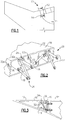
- an aircraft 10 includes a first component and a second component.
- the first component is a trailing edge assembly 12.
- the second component is an airframe structure 14.
- the trailing edge assembly 12 and the airframe 14 have different coefficients of thermal expansion.
- the trailing edge assembly 12 is a ceramic matrix composite component
- the airframe 14 is a metallic material.
- the first component and the second component have the same coefficient of thermal expansion, but are exposed to different temperatures.
- the example trailing edge assembly 12 includes an outer shell 16 and ribs 18 spanning opposing walls of the outer shell 16.
- a mounting assembly 20 is secured to the ribs 18 to connect the trailing edge assembly 12 to the airframe 14.
- the mounting assembly 20 includes a plurality of linking members 22.
- Each of the linking members 22 extends between a first end 24 and a second end 26. The first end 24 is secured to the ribs 18, and the second end 26 is secured to the mounting assembly 20.
- brackets 30 are also secured to the trailing edge assembly 12.
- the example brackets 30 are P-clamps used to support wiring, tubing, etc.
- a plurality of fastening assemblies 32a and 32b engage the trailing edge assembly 12.
- the brackets 30 are each secured to the trailing edge assembly 12 with one the fastening assemblies 32a.
- the first ends 24 of the linking members 22 are secured to the trailing edge assembly 12 with one of the fastening assemblies 32b.
- the example fastening assembly 32a extends through an aperture 34 established in one of the ribs 18 of the trailing edge assembly 12.
- the example fastening assembly 32a includes a bolt 35 having a head 36.
- the fastening assembly 32a also includes a nut 38.
- a portion of the fastening assembly 32a is on a head side of the rib 18, and another portion of the fastening assembly 32a is on a nut side of the rib 18.
- Another portion of the fastening assembly 32a extends through the aperture 34 and is radially spaced from the rib 18.
- a Belleville washer 40h, a flat washer 42h, a felt metal gasket 44h, and a foil layer 46h are clamped between the head 36 and the rib 18 when the bolt 35 and the nut 38 are tightened relative to each other.
- a Belleville washer 40n, a flat washer 42n, a felt metal gasket 44n, and a foil layer 46n are compressed against the wall as the bolt 35 is tightened relative to the nut 38.
- a portion of the bracket 30 is clamped between the Belleville washer 40n and the flat washer 42n as the bolt 35 is tightened relative to the nut 38.
- Tightening the bolt 35 relative to the nut 38 causes the flat washers 42h and 42n to compress the layers of the felt metal gasket 44h and 44n against opposing sides of the rib 18.
- the flat washers 42h and 42n distribute the load exerted on the rib 18 due to the bolt 35 tightening relative to the nut 38.
- the example felt metal gasket 44h and 44n is made of non-woven or loosely packed metallic fibers.
- Candidate metal fiber materials include oxidation resistant materials such as stainless steel and Inconel alloys. Typical fiber diameters can range from 0.00015 inches to 0.005 inches (4 micrometers to 130 micrometers).
- the clamping bolt 35 should be retorqued at least twice over a twenty-four hour period to compensate for the relaxation that will exist as the metal fibers take a compression set.
- the example rib 18 is made of a ceramic matrix composite material, which is a relatively brittle material prone to wear and damage, particularly when the mating surface is metal.
- the foil layer 46 prevents the fibers of the felt metal gasket 44h and 44n from directly contacting the rib 18, which could cut, or otherwise damage, the rib 18. As the layers of the felt metal gasket 44h and 44n are compressed toward the rib 18, the foil layers 46h and 46n are compressed against the surfaces of the rib 18.
- the foil layers 46h and 46n are between 0.002 to 0.003 inches (0.0508 to 0.0762 millimeters) thick in this example.
- the surfaces of the rib 18 typically have many irregularities, which is another characteristic of ceramic matrix composite materials.
- the example foil layers 46h and 46n include a plurality of slices 48 that enhance the pliability of the foil layers 46h and 46n when compressed. That is, the slices 48 make the foil layers 46h and 46n more compliant. In one example, the slices 48 extend through the entire thickness of the foil layers 46h and 46n and establish flaps within the foil layers 46h and 46n. In another example, the slices do not extend through the entire thickness of the foil layers 46h and 46n instead are scored areas of the foil layers 46h and 46n.
- the example fastening assembly 32a clamps the bracket 30 relative to the rib 18. Notably, only the foil layers 46h and 46n directly contact the rib 18. The conformance of the felt metal gaskets 44h and 44n to the surfaces of the rib 18, through the foil layers 46h and 46n, discourages movement of the bolt 35 radially toward a position where a shank of the bolt 35 would contact the rib 18. The shank of the bolt 35 is radially spaced from the rib 18 in this example.
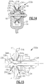
- FIG. 8-12 another example fastener assembly 132a is configured to secure the bracket 130 against the rib 118.
- the fastener assembly 132a includes a split sleeve assembly 50 configured to exert a radial force against a felt metal gasket layer 144a positioned within the aperture 134.
- the felt metal gasket layer 144a when compressed, forces a foil layer 146a against portions of the rib 118 that define the aperture 134.
- the foil layer 146a is wrapped around the outer diameter of the felt metal gasket layer 144a prior to insertion into the aperture 134.
- the example split sleeve assembly 50 includes an inner sleeve 52 and an outer sleeve 54.
- the flat washers 142h and 142n force the inner sleeve 52 axially toward the outer sleeve 54.
- the facing ends of the inner sleeve 52 and the outer sleeve 54 are beveled, which encourages the inner sleeve 52 to be received within the outer sleeve 54 after sufficient axial movement.
- the bevel of the inner sleeve 52 is between 30 and 60 degrees
- the bevel on the outer sleeve 54 is between 30 and 60 degrees.
- the inner sleeve 52 and the outer sleeve 54 each include a slot 56 to accommodate movement of the inner sleeve 52 and the outer sleeve 54 as the inner sleeve 52 is received within the outer sleeve 54 during assembly.
- the slots 56 are helical slots in this example.
- the outer sleeve 54 As the inner sleeve 52 is received within the outer sleeve 54, the outer sleeve 54 is forced radially outward away from the bolt 135. The movement of the outer sleeve 54 compresses the felt metal gasket 144a and forces the foil layer 146a against the rib 118. The felt metal gasket 144a blocks contact between the shank of the bolt 135 and the rib 118 within the aperture 134. Also, when the head 136 of the bolt 135 is sufficiently tightened relative to the nut 138, the flat washers 142h and 142n compress the felt metal gaskets 144h and 144n.
- the axial length of the outer sleeve 54 and the inner sleeve 52 is less than the distance between the flat washers 142h and 142n when the bolt 135 is fully tightened relative to the nut 138. This ensures that contact between the flat washer 142h and the inner sleeve 52 does not prevent tightening of the bolt 135 relative to the nut 138.
- the inner sleeve 52 is spaced between 0.020 to 0.030 inches (0.508 to 0.762 millimeters) from the flat washer 142h when the bolt 135 is fully tightened relative to the nut 138.
- a fastening assembly 232b may be used to secure the first ends 24 of the linking members 22 to the trailing edge assembly 12.
- the head 236 of the example fastening assembly 232b is conical, as is the nut 238.
- the rib 218 is countersunk at areas 58 and 60 to accommodate the beveled portions of the head 236 and nut 238, respectively.
- the aperture 234 is chamfered at opposing axial ends because the rib 218 is countersunk at the areas 58 and 60.
- receiving the head 236 within the countersunk area 58 facilitates centering the bolt 235 when tightened relative to the nut 238.
- receiving the nut 238 within the countersunk area 60 facilitates centering the nut 238 when tightened relative to the bolt 235. Centering the fastening assembly 232b helps reduce the likelihood of contact between the bolt 235 and the rib 218.
- the bolt 235 defines a socket 62 configured to receive a ball fastener 64.
- the ball fastener 64 is connected to one of the linking members 22 through a second bolt 66.
- Using the ball fastener 64 and socket 62 facilitates movement of the linking member 22 relative to the rib 218.
- no washer is positioned between the bolt head 236 and the felt metal gasket layer 244h, and no washer is positioned between the nut 238 and the foil layer 244n.
- the fastening assembly 232b may include felt metal material extending through the aperture 234, as does the fastening assembly 132a ( Figure 8 ).
- a fastening assembly 332h may be used to secure the first ends 24 of the linking members 22.
- portions of the rib 318 include built up areas 68h that provide a countersunk area 358 that is used to accommodate a beveled washer 70h.
- the rib 318 also includes built-up areas 68n that provide a countersunk area 360 that is used to accommodate a beveled washer 70n.
- the angle of the beveled area 70h is not the same as the angle of the beveled area 70n. More specifically, a bevel angle ⁇ h of the head 336 is 45 degrees, and a bevel angle ⁇ n of the nut 338 is 60 degrees.
- fastening assemblies that conform to surface irregularities and provide effective load distribution for securing to relatively brittle components.
- the fastening assemblies are particularly suitable for securing components having differing coefficients of thermal expansion.
Landscapes
- Engineering & Computer Science (AREA)
- General Engineering & Computer Science (AREA)
- Mechanical Engineering (AREA)
- Aviation & Aerospace Engineering (AREA)
- Gasket Seals (AREA)
- Connection Of Plates (AREA)
Claims (15)
- Ensemble de montage (20), comprenant une fixation (35 ; 135 ; 235 ; 335) recevable dans une ouverture (34 ; 134 ; 234) d'un composant (12), caractérisé en ce que :l'ensemble de montage (20) comprend en outre au moins un premier joint en feutre métallique (44h, 44n ; 144a, 144h, 144n ; 244h, 244n ; 344h, 344n) séparant la fixation (35 ; 135 ; 235 ; 335) du composant (12).
- Ensemble de montage (20) selon la revendication 1, dans lequel le composant (12) est un composant composite à matrice céramique.
- Ensemble de montage (20) selon la revendication 1 ou 2, incluant une couche de feuille métallique (46h ; 46n ; 146a, 146h, 146n) configurée pour être positionnée entre l'au moins un joint en feutre métallique (44h, 44n ; 144a, 144h, 144n) et le composant (12) et facultativement dans lequel ladite couche de feuille métallique (46h ; 46n ; 146a, 146h, 146n) est flexible.
- Ensemble de montage (20) selon la revendication 3, dans lequel la couche de feuille métallique (46n) inclut une pluralité de tranches (48).
- Ensemble de montage (20) selon la revendication 4, dans lequel la pluralité de tranches (48) s'étendent à travers toute l'épaisseur de la couche de feuille métallique (46n).
- Ensemble de montage (20) selon une quelconque revendication précédente, dans lequel la fixation (235) établit une articulation (62) configurée pour recevoir une rotule (64).
- Ensemble de montage (20) selon une quelconque revendication précédente, dans lequel l'ouverture (234) inclut une zone chanfreinée à chaque extrémité axiale de l'ouverture (234), et la fixation (235) inclut une partie conique respective (236) reçue dans chaque zone chanfreinée.
- Ensemble de montage (20) selon une quelconque revendication précédente, dans lequel le joint en feutre métallique (144a) garnit la totalité de l'ouverture (134), et/ou s'étend le long de toute la longueur axiale de l'ouverture (134) et d'environ toute la périphérie de l'ouverture (134).
- Ensemble de montage (20) selon une quelconque revendication précédente, dans lequel un fourreau fendu (50) reçu sur au moins une partie de la fixation (135) et configuré pour exercer une force radialement vers l'extérieur s'éloignant de la fixation (135) pour comprimer le joint en feutre métallique (144a) contre le composant (12).
- Ensemble de montage (20) selon une quelconque revendication précédente, dans lequel ledit composant (12) est un premier composant (12) ayant un premier coefficient d'expansion thermique, et ledit ensemble de montage (20) comprend en outre :un second composant (14) ayant un second coefficient d'expansion thermique ; etun élément de liaison (22) ayant une première partie (24) fixée au premier composant (12) et une seconde partie (22) fixée au second composant (14) ; dans lequel ladite fixation (35 ; 135 ; 235 ; 335) fixe l'élément de liaison au premier composant (12) et ladite fixation (35 ; 135 ; 235 ; 335) est reçue dans ladite ouverture (34 ; 134 ; 234) du premier composant (12).
- Ensemble de montage (20) selon la revendication 10, dans lequel le premier composant (12) ou le second composant (14) est un ensemble de bord de fuite d'un avion et l'autre du premier composant ou du second composant est une structure de cellule métallique de l'avion.
- Ensemble de montage (20) selon la revendication 10 ou 11, dans lequel le premier composant (12) et le second composant (14) sont constitués de matériaux différents.
- Procédé de montage d'un premier composant (12) sur un second composant (14), comprenant la réception d'au moins un ensemble de fixation (32a, 32b ; 132a ; 232b ; 332b) dans une ouverture (34 ; 134 ; 234) établie dans le premier composant (12), l'ensemble de fixation (32a, 32b ; 132a ; 232b ; 332b) couplé au second composant (14) au moyen d'un élément de liaison (22), caractérisé par :le positionnement d'un matériau en feutre métallique (44h, 44n ; 144a, 144h, 144n ; 244h, 244a ; 344h, 344n) entre l'ensemble de fixation (32a, 32b ; 132a ; 232b ; 332b) et le premier composant (12) ;la fixation de l'ensemble de fixation (32a, 32b ; 132a ; 232b ; 332b) ; etla compression du matériau en feutre métallique (44h, 44n ; 144a, 144h, 144n ; 244h, 244a ; 344h, 344n) pendant la fixation.
- Procédé de montage selon la revendication 13, dans lequel le positionnement est effectué avant la réception.
- Procédé de montage selon la revendication 13 ou 14, incluant la séparation du premier composant (12) du matériau en feutre métallique (44h, 44n ; 144a, 144h, 144n ; 244h, 244a ; 344h, 344n) en utilisant une couche de feuille métallique (46h, 46n ; 146a, 146h, 146n).
Applications Claiming Priority (1)
| Application Number | Priority Date | Filing Date | Title |
|---|---|---|---|
| US13/157,276 US10059431B2 (en) | 2011-06-09 | 2011-06-09 | Method and apparatus for attaching components having dissimilar rates of thermal expansion |
Publications (3)
| Publication Number | Publication Date |
|---|---|
| EP2532584A2 EP2532584A2 (fr) | 2012-12-12 |
| EP2532584A3 EP2532584A3 (fr) | 2016-12-28 |
| EP2532584B1 true EP2532584B1 (fr) | 2018-11-07 |
Family
ID=46197112
Family Applications (1)
| Application Number | Title | Priority Date | Filing Date |
|---|---|---|---|
| EP12170590.9A Active EP2532584B1 (fr) | 2011-06-09 | 2012-06-01 | Procédé et appareil permettant de fixer des composants ayant des taux différents d'expansion thermique |
Country Status (2)
| Country | Link |
|---|---|
| US (2) | US10059431B2 (fr) |
| EP (1) | EP2532584B1 (fr) |
Families Citing this family (5)
| Publication number | Priority date | Publication date | Assignee | Title |
|---|---|---|---|---|
| GB201113065D0 (en) * | 2011-07-29 | 2011-09-14 | Airbus Uk Ltd | Aircraft glazing attachment |
| CN106015235B (zh) * | 2016-05-25 | 2019-03-01 | 江西洪都航空工业集团有限责任公司 | 一种便捷安装防差错组合垫块 |
| US10447197B2 (en) * | 2016-12-14 | 2019-10-15 | Tecsi Solar, Inc. | Systems and methods for mounting roof-mounted photovoltaic arrays including flashing and adhesive pads |
| CN108216577A (zh) * | 2017-12-08 | 2018-06-29 | 西安飞机工业(集团)有限责任公司 | 一种飞机襟翼接头连接的保险结构 |
| CN115559972B (zh) * | 2022-11-03 | 2026-04-17 | 西安鑫垚陶瓷复合材料股份有限公司 | 用于金属-陶瓷基复材的连接组件、金属-陶瓷基复材构件 |
Family Cites Families (58)
| Publication number | Priority date | Publication date | Assignee | Title |
|---|---|---|---|---|
| US1596856A (en) * | 1924-11-08 | 1926-08-17 | John C Setlow | Expansion bushing for bolts |
| US3016746A (en) | 1960-07-08 | 1962-01-16 | Johnson Service Co | Differential temperature controllers |
| US3070953A (en) | 1961-05-18 | 1963-01-01 | Ralph E Carrel | Temperature operated prime mover |
| US3140066A (en) * | 1962-12-04 | 1964-07-07 | North American Aviation Inc | Multiple pivot mounting means |
| US3675376A (en) | 1971-02-12 | 1972-07-11 | Nasa | Thermal compensating structural member |
| US4243192A (en) * | 1978-12-04 | 1981-01-06 | Mcdonnell Douglas Corporation | Ball pivot thrust bearing flex joint |
| US4243189A (en) | 1978-12-18 | 1981-01-06 | The Boeing Company | Temperature stabilized linkage |
| US4411594A (en) | 1979-06-30 | 1983-10-25 | Rolls-Royce Limited | Support member and a component supported thereby |
| US4312599A (en) * | 1979-10-22 | 1982-01-26 | General Electric Company | High temperature article, article retainer, and cushion |
| US4450687A (en) | 1980-03-17 | 1984-05-29 | Thermoforce Limited | Temperature responsive actuating device |
| DE3013774A1 (de) * | 1980-04-10 | 1981-10-15 | Vereinigte Flugtechnische Werke Gmbh, 2800 Bremen | Betaetigungsanordnung fuer fluegelklappen |
| US4556591A (en) * | 1981-09-25 | 1985-12-03 | The Boeing Company | Conductive bonded/bolted joint seals for composite aircraft |
| US4411954A (en) | 1982-08-16 | 1983-10-25 | National Starch And Chemical Corporation | Hot melt pressure sensitive adhesive and diaper tape closures coated therewith |
| FR2580342B1 (fr) * | 1985-04-16 | 1988-05-13 | Dutton Hugh | Attache mecanique de materiaux en plaques a une structure de support vertical desdits materiaux |
| JPS6256784A (ja) | 1985-09-05 | 1987-03-12 | Mitsubishi Heavy Ind Ltd | エアヒ−タのシ−ル隙間調整装置 |
| US4834569A (en) * | 1987-05-13 | 1989-05-30 | The Boeing Company | Thermal expansion compensating joint assembly |
| US4863122A (en) | 1987-06-24 | 1989-09-05 | The Boeing Company | Aircraft rudder thermal compensation linkage |
| US4841100A (en) | 1987-09-02 | 1989-06-20 | Minnesota Mining And Manufacturing Company | Expanding surface mount compatible retainer post |
| US4861229A (en) | 1987-11-16 | 1989-08-29 | Williams International Corporation | Ceramic-matrix composite nozzle assembly for a turbine engine |
| US5015116A (en) | 1988-08-22 | 1991-05-14 | United Technologies Corporation | Structural joints of high dimensional stability |
| US5228795A (en) * | 1989-12-27 | 1993-07-20 | Rohr, Inc. | Self-tightening fitting for attachment of metal to carbon-carbon structures |
| US5120175A (en) | 1991-07-15 | 1992-06-09 | Arbegast William J | Shape memory alloy fastener |
| US6425829B1 (en) | 1994-12-06 | 2002-07-30 | Nitinol Technologies, Inc. | Threaded load transferring attachment |
| US5592814A (en) * | 1994-12-21 | 1997-01-14 | United Technologies Corporation | Attaching brittle composite structures in gas turbine engines for resiliently accommodating thermal expansion |
| FR2735187B1 (fr) | 1995-06-06 | 1997-08-29 | Aerospatiale | Poussoir a actionnement unique motorise par un materiau a memoire de forme. |
| DE19536982A1 (de) | 1995-10-04 | 1997-04-17 | Deutsche Forsch Luft Raumfahrt | Verfahren und Vorrichtung zur Übertragung von Kräften zwischen zwei Fügeteilen |
| US5718531A (en) | 1996-01-22 | 1998-02-17 | Lockheed Martin Corporation | Low shock release device |
| ATE241504T1 (de) | 1996-02-05 | 2003-06-15 | 3M Espe Ag | Vorrichtung zum entleeren eines schlauchbeutels |
| US6175989B1 (en) | 1998-05-26 | 2001-01-23 | Lockheed Corp | Shape memory alloy controllable hinge apparatus |
| GB9818052D0 (en) | 1998-08-20 | 1998-10-14 | British Aerospace | Fastening arrangements |
| US6171009B1 (en) | 1998-10-20 | 2001-01-09 | Lockheed Martin Corporation | Method and apparatus for temperature-stabilizing a joint |
| US6126371A (en) | 1999-04-05 | 2000-10-03 | Lockheed Martin Corporation | Shape memory metal alloy preload attenuation device |
| US20030170092A1 (en) | 1999-12-22 | 2003-09-11 | Chiodo Joseph David | Releasable fasteners |
| DE10021575C2 (de) * | 2000-05-03 | 2002-09-19 | Elringklinger Ag | Vorrichtung zur akustisch entkoppelten Befestigung von Hitzeschildern oder ähnlichen leicht schwingfähigen Bauteilen |
| ATE284346T1 (de) | 2001-01-26 | 2004-12-15 | Fischer Adv Components Gmbh | Einrichtung zum verbinden beweglicher teile mit strukturbauteilen von flugzeugen od. dgl. |
| FR2825780B1 (fr) | 2001-06-06 | 2003-08-29 | Snecma Moteurs | Architecure de chambre de combustion de turbomachine en materiau a matrice ceramique |
| US7416362B2 (en) * | 2002-08-16 | 2008-08-26 | Siemens Power Generation, Inc. | Multidirectionally compliant fastening system |
| US6758653B2 (en) | 2002-09-09 | 2004-07-06 | Siemens Westinghouse Power Corporation | Ceramic matrix composite component for a gas turbine engine |
| US6910853B2 (en) | 2002-11-27 | 2005-06-28 | General Electric Company | Structures for attaching or sealing a space between components having different coefficients or rates of thermal expansion |
| US6895761B2 (en) | 2002-12-20 | 2005-05-24 | General Electric Company | Mounting assembly for the aft end of a ceramic matrix composite liner in a gas turbine engine combustor |
| US7422403B1 (en) | 2003-10-23 | 2008-09-09 | Tini Alloy Company | Non-explosive releasable coupling device |
| JP2005247222A (ja) | 2004-03-05 | 2005-09-15 | Honda Motor Co Ltd | 車両用部品固定解除装置 |
| JP4339167B2 (ja) | 2004-04-07 | 2009-10-07 | 本田技研工業株式会社 | 締結装置 |
| DE102004041685B3 (de) | 2004-08-26 | 2006-05-04 | Bayer Materialscience Ag | Verbundbauteil |
| US7647779B2 (en) | 2005-04-27 | 2010-01-19 | United Technologies Corporation | Compliant metal support for ceramic combustor liner in a gas turbine engine |
| US7665960B2 (en) | 2006-08-10 | 2010-02-23 | United Technologies Corporation | Turbine shroud thermal distortion control |
| US7771160B2 (en) | 2006-08-10 | 2010-08-10 | United Technologies Corporation | Ceramic shroud assembly |
| US8556531B1 (en) * | 2006-11-17 | 2013-10-15 | United Technologies Corporation | Simple CMC fastening system |
| US7878459B2 (en) | 2007-06-29 | 2011-02-01 | The Boeing Company | Aircraft systems with shape memory alloy (SMA) actuators, and associated methods |
| US7967570B2 (en) | 2007-07-27 | 2011-06-28 | United Technologies Corporation | Low transient thermal stress turbine engine components |
| US7968021B2 (en) | 2007-07-31 | 2011-06-28 | The Boeing Company | Coefficient of thermal expansion control structure |
| US20090067917A1 (en) | 2007-09-07 | 2009-03-12 | The Boeing Company | Bipod Flexure Ring |
| ES2310149B1 (es) | 2008-02-18 | 2009-11-16 | Thyssenkrupp Elevator Innovation Center S.A. | Cubierta extensible para pasarelas de acceso a aeronaves. |
| US20090226327A1 (en) | 2008-03-07 | 2009-09-10 | Siemens Power Generation, Inc. | Gas Turbine Engine Including Temperature Control Device and Method Using Memory Metal |
| ITTO20080566A1 (it) | 2008-07-23 | 2010-01-24 | Alenia Aeronautica Spa | Dispositivo attuatore basato su lega a memoria di forma e gruppo di flap alare dotato di un tale dispositivo attuatore |
| US20100050399A1 (en) | 2008-08-28 | 2010-03-04 | Gm Gloal Technology Operations , Inc. | Active material based clamping apparatuses and methods of making |
| GB2467584B (en) | 2009-02-10 | 2010-12-29 | Rolls Royce Plc | An assembly |
| US8745989B2 (en) | 2009-04-09 | 2014-06-10 | Pratt & Whitney Canada Corp. | Reverse flow ceramic matrix composite combustor |
-
2011
- 2011-06-09 US US13/157,276 patent/US10059431B2/en active Active
-
2012
- 2012-06-01 EP EP12170590.9A patent/EP2532584B1/fr active Active
-
2018
- 2018-07-25 US US16/045,008 patent/US10669007B2/en active Active
Non-Patent Citations (1)
| Title |
|---|
| None * |
Also Published As
| Publication number | Publication date |
|---|---|
| US10669007B2 (en) | 2020-06-02 |
| US20120311846A1 (en) | 2012-12-13 |
| EP2532584A2 (fr) | 2012-12-12 |
| US20180346097A1 (en) | 2018-12-06 |
| US10059431B2 (en) | 2018-08-28 |
| EP2532584A3 (fr) | 2016-12-28 |
Similar Documents
| Publication | Publication Date | Title |
|---|---|---|
| US10669007B2 (en) | Method and apparatus for attaching components having dissimilar rates of thermal expansion | |
| US9254908B2 (en) | Fixing means | |
| EP1467135B1 (fr) | Collier ajustable latéralement | |
| EP2932145B1 (fr) | Pont jointé pour ensemble de serrage | |
| EP3833896B1 (fr) | Ensemble collier de serrage avec dispositif de retenue | |
| CN107208826B (zh) | 管夹 | |
| CA2584746A1 (fr) | Appareil et procede pour collier | |
| JP2005249183A (ja) | 雌取付けアセンブリおよび継手アセンブリ | |
| GB2288205A (en) | Band clamp | |
| EP2737239B1 (fr) | Ensemble de serrage à bande souple pourvue de sillons | |
| KR20190006084A (ko) | 브래킷리스 클램핑 조립체 | |
| US10012258B2 (en) | Locking device for a threaded fastener | |
| EP3237763B1 (fr) | Écrou de compensation | |
| WO2011090382A1 (fr) | Système d'éléments de fixation définis par un écrou et une barre de traction ; barre de traction et écrou | |
| US20030025329A1 (en) | Spacer-less type pipe joint and packing ring used for the same | |
| WO2004084352A1 (fr) | Systeme de raccordement electrique et de fixation d'au moins un conducteur sur une piece de support | |
| WO2004084350A2 (fr) | Systeme de raccordement electrique et de fixation d'au moins un conducteur sur une piece de support | |
| US4300738A (en) | Duct support structure | |
| US6062783A (en) | Expanding bush and captive bolt assembly | |
| KR20140081164A (ko) | 복수의 내경을 갖는 이경 클램프 | |
| JPH07127765A (ja) | 長尺体支持具 | |
| KR101185765B1 (ko) | 풀림 방지 플랜지 너트 | |
| EP2156083B1 (fr) | Bride pour la suspension d'un conduit | |
| JP3380014B2 (ja) | 長尺体支持具 | |
| KR101920632B1 (ko) | 트랙션 시브 클램핑 장치 |
Legal Events
| Date | Code | Title | Description |
|---|---|---|---|
| PUAI | Public reference made under article 153(3) epc to a published international application that has entered the european phase |
Free format text: ORIGINAL CODE: 0009012 |
|
| AK | Designated contracting states |
Kind code of ref document: A2 Designated state(s): AL AT BE BG CH CY CZ DE DK EE ES FI FR GB GR HR HU IE IS IT LI LT LU LV MC MK MT NL NO PL PT RO RS SE SI SK SM TR |
|
| AX | Request for extension of the european patent |
Extension state: BA ME |
|
| RAP1 | Party data changed (applicant data changed or rights of an application transferred) |
Owner name: UNITED TECHNOLOGIES CORPORATION |
|
| PUAL | Search report despatched |
Free format text: ORIGINAL CODE: 0009013 |
|
| AK | Designated contracting states |
Kind code of ref document: A3 Designated state(s): AL AT BE BG CH CY CZ DE DK EE ES FI FR GB GR HR HU IE IS IT LI LT LU LV MC MK MT NL NO PL PT RO RS SE SI SK SM TR |
|
| AX | Request for extension of the european patent |
Extension state: BA ME |
|
| RIC1 | Information provided on ipc code assigned before grant |
Ipc: B64C 13/30 20060101AFI20161121BHEP |
|
| STAA | Information on the status of an ep patent application or granted ep patent |
Free format text: STATUS: REQUEST FOR EXAMINATION WAS MADE |
|
| 17P | Request for examination filed |
Effective date: 20170425 |
|
| RBV | Designated contracting states (corrected) |
Designated state(s): AL AT BE BG CH CY CZ DE DK EE ES FI FR GB GR HR HU IE IS IT LI LT LU LV MC MK MT NL NO PL PT RO RS SE SI SK SM TR |
|
| STAA | Information on the status of an ep patent application or granted ep patent |
Free format text: STATUS: EXAMINATION IS IN PROGRESS |
|
| 17Q | First examination report despatched |
Effective date: 20170915 |
|
| GRAP | Despatch of communication of intention to grant a patent |
Free format text: ORIGINAL CODE: EPIDOSNIGR1 |
|
| STAA | Information on the status of an ep patent application or granted ep patent |
Free format text: STATUS: GRANT OF PATENT IS INTENDED |
|
| INTG | Intention to grant announced |
Effective date: 20180515 |
|
| GRAS | Grant fee paid |
Free format text: ORIGINAL CODE: EPIDOSNIGR3 |
|
| GRAA | (expected) grant |
Free format text: ORIGINAL CODE: 0009210 |
|
| STAA | Information on the status of an ep patent application or granted ep patent |
Free format text: STATUS: THE PATENT HAS BEEN GRANTED |
|
| AK | Designated contracting states |
Kind code of ref document: B1 Designated state(s): AL AT BE BG CH CY CZ DE DK EE ES FI FR GB GR HR HU IE IS IT LI LT LU LV MC MK MT NL NO PL PT RO RS SE SI SK SM TR |
|
| REG | Reference to a national code |
Ref country code: GB Ref legal event code: FG4D |
|
| REG | Reference to a national code |
Ref country code: CH Ref legal event code: EP Ref country code: AT Ref legal event code: REF Ref document number: 1061747 Country of ref document: AT Kind code of ref document: T Effective date: 20181115 |
|
| REG | Reference to a national code |
Ref country code: DE Ref legal event code: R096 Ref document number: 602012053089 Country of ref document: DE |
|
| REG | Reference to a national code |
Ref country code: IE Ref legal event code: FG4D |
|
| REG | Reference to a national code |
Ref country code: NL Ref legal event code: MP Effective date: 20181107 |
|
| REG | Reference to a national code |
Ref country code: LT Ref legal event code: MG4D |
|
| REG | Reference to a national code |
Ref country code: AT Ref legal event code: MK05 Ref document number: 1061747 Country of ref document: AT Kind code of ref document: T Effective date: 20181107 |
|
| PG25 | Lapsed in a contracting state [announced via postgrant information from national office to epo] |
Ref country code: ES Free format text: LAPSE BECAUSE OF FAILURE TO SUBMIT A TRANSLATION OF THE DESCRIPTION OR TO PAY THE FEE WITHIN THE PRESCRIBED TIME-LIMIT Effective date: 20181107 Ref country code: LT Free format text: LAPSE BECAUSE OF FAILURE TO SUBMIT A TRANSLATION OF THE DESCRIPTION OR TO PAY THE FEE WITHIN THE PRESCRIBED TIME-LIMIT Effective date: 20181107 Ref country code: BG Free format text: LAPSE BECAUSE OF FAILURE TO SUBMIT A TRANSLATION OF THE DESCRIPTION OR TO PAY THE FEE WITHIN THE PRESCRIBED TIME-LIMIT Effective date: 20190207 Ref country code: NO Free format text: LAPSE BECAUSE OF FAILURE TO SUBMIT A TRANSLATION OF THE DESCRIPTION OR TO PAY THE FEE WITHIN THE PRESCRIBED TIME-LIMIT Effective date: 20190207 Ref country code: IS Free format text: LAPSE BECAUSE OF FAILURE TO SUBMIT A TRANSLATION OF THE DESCRIPTION OR TO PAY THE FEE WITHIN THE PRESCRIBED TIME-LIMIT Effective date: 20190307 Ref country code: HR Free format text: LAPSE BECAUSE OF FAILURE TO SUBMIT A TRANSLATION OF THE DESCRIPTION OR TO PAY THE FEE WITHIN THE PRESCRIBED TIME-LIMIT Effective date: 20181107 Ref country code: LV Free format text: LAPSE BECAUSE OF FAILURE TO SUBMIT A TRANSLATION OF THE DESCRIPTION OR TO PAY THE FEE WITHIN THE PRESCRIBED TIME-LIMIT Effective date: 20181107 Ref country code: AT Free format text: LAPSE BECAUSE OF FAILURE TO SUBMIT A TRANSLATION OF THE DESCRIPTION OR TO PAY THE FEE WITHIN THE PRESCRIBED TIME-LIMIT Effective date: 20181107 Ref country code: FI Free format text: LAPSE BECAUSE OF FAILURE TO SUBMIT A TRANSLATION OF THE DESCRIPTION OR TO PAY THE FEE WITHIN THE PRESCRIBED TIME-LIMIT Effective date: 20181107 |
|
| PG25 | Lapsed in a contracting state [announced via postgrant information from national office to epo] |
Ref country code: SE Free format text: LAPSE BECAUSE OF FAILURE TO SUBMIT A TRANSLATION OF THE DESCRIPTION OR TO PAY THE FEE WITHIN THE PRESCRIBED TIME-LIMIT Effective date: 20181107 Ref country code: NL Free format text: LAPSE BECAUSE OF FAILURE TO SUBMIT A TRANSLATION OF THE DESCRIPTION OR TO PAY THE FEE WITHIN THE PRESCRIBED TIME-LIMIT Effective date: 20181107 Ref country code: GR Free format text: LAPSE BECAUSE OF FAILURE TO SUBMIT A TRANSLATION OF THE DESCRIPTION OR TO PAY THE FEE WITHIN THE PRESCRIBED TIME-LIMIT Effective date: 20190208 Ref country code: AL Free format text: LAPSE BECAUSE OF FAILURE TO SUBMIT A TRANSLATION OF THE DESCRIPTION OR TO PAY THE FEE WITHIN THE PRESCRIBED TIME-LIMIT Effective date: 20181107 Ref country code: RS Free format text: LAPSE BECAUSE OF FAILURE TO SUBMIT A TRANSLATION OF THE DESCRIPTION OR TO PAY THE FEE WITHIN THE PRESCRIBED TIME-LIMIT Effective date: 20181107 Ref country code: PT Free format text: LAPSE BECAUSE OF FAILURE TO SUBMIT A TRANSLATION OF THE DESCRIPTION OR TO PAY THE FEE WITHIN THE PRESCRIBED TIME-LIMIT Effective date: 20190307 |
|
| PG25 | Lapsed in a contracting state [announced via postgrant information from national office to epo] |
Ref country code: DK Free format text: LAPSE BECAUSE OF FAILURE TO SUBMIT A TRANSLATION OF THE DESCRIPTION OR TO PAY THE FEE WITHIN THE PRESCRIBED TIME-LIMIT Effective date: 20181107 Ref country code: IT Free format text: LAPSE BECAUSE OF FAILURE TO SUBMIT A TRANSLATION OF THE DESCRIPTION OR TO PAY THE FEE WITHIN THE PRESCRIBED TIME-LIMIT Effective date: 20181107 Ref country code: CZ Free format text: LAPSE BECAUSE OF FAILURE TO SUBMIT A TRANSLATION OF THE DESCRIPTION OR TO PAY THE FEE WITHIN THE PRESCRIBED TIME-LIMIT Effective date: 20181107 Ref country code: PL Free format text: LAPSE BECAUSE OF FAILURE TO SUBMIT A TRANSLATION OF THE DESCRIPTION OR TO PAY THE FEE WITHIN THE PRESCRIBED TIME-LIMIT Effective date: 20181107 |
|
| REG | Reference to a national code |
Ref country code: DE Ref legal event code: R097 Ref document number: 602012053089 Country of ref document: DE |
|
| PG25 | Lapsed in a contracting state [announced via postgrant information from national office to epo] |
Ref country code: RO Free format text: LAPSE BECAUSE OF FAILURE TO SUBMIT A TRANSLATION OF THE DESCRIPTION OR TO PAY THE FEE WITHIN THE PRESCRIBED TIME-LIMIT Effective date: 20181107 Ref country code: SK Free format text: LAPSE BECAUSE OF FAILURE TO SUBMIT A TRANSLATION OF THE DESCRIPTION OR TO PAY THE FEE WITHIN THE PRESCRIBED TIME-LIMIT Effective date: 20181107 Ref country code: EE Free format text: LAPSE BECAUSE OF FAILURE TO SUBMIT A TRANSLATION OF THE DESCRIPTION OR TO PAY THE FEE WITHIN THE PRESCRIBED TIME-LIMIT Effective date: 20181107 Ref country code: SM Free format text: LAPSE BECAUSE OF FAILURE TO SUBMIT A TRANSLATION OF THE DESCRIPTION OR TO PAY THE FEE WITHIN THE PRESCRIBED TIME-LIMIT Effective date: 20181107 |
|
| PLBE | No opposition filed within time limit |
Free format text: ORIGINAL CODE: 0009261 |
|
| STAA | Information on the status of an ep patent application or granted ep patent |
Free format text: STATUS: NO OPPOSITION FILED WITHIN TIME LIMIT |
|
| 26N | No opposition filed |
Effective date: 20190808 |
|
| PG25 | Lapsed in a contracting state [announced via postgrant information from national office to epo] |
Ref country code: SI Free format text: LAPSE BECAUSE OF FAILURE TO SUBMIT A TRANSLATION OF THE DESCRIPTION OR TO PAY THE FEE WITHIN THE PRESCRIBED TIME-LIMIT Effective date: 20181107 |
|
| PG25 | Lapsed in a contracting state [announced via postgrant information from national office to epo] |
Ref country code: MC Free format text: LAPSE BECAUSE OF FAILURE TO SUBMIT A TRANSLATION OF THE DESCRIPTION OR TO PAY THE FEE WITHIN THE PRESCRIBED TIME-LIMIT Effective date: 20181107 |
|
| REG | Reference to a national code |
Ref country code: CH Ref legal event code: PL |
|
| REG | Reference to a national code |
Ref country code: BE Ref legal event code: MM Effective date: 20190630 |
|
| PG25 | Lapsed in a contracting state [announced via postgrant information from national office to epo] |
Ref country code: TR Free format text: LAPSE BECAUSE OF FAILURE TO SUBMIT A TRANSLATION OF THE DESCRIPTION OR TO PAY THE FEE WITHIN THE PRESCRIBED TIME-LIMIT Effective date: 20181107 |
|
| PG25 | Lapsed in a contracting state [announced via postgrant information from national office to epo] |
Ref country code: IE Free format text: LAPSE BECAUSE OF NON-PAYMENT OF DUE FEES Effective date: 20190601 |
|
| PG25 | Lapsed in a contracting state [announced via postgrant information from national office to epo] |
Ref country code: LI Free format text: LAPSE BECAUSE OF NON-PAYMENT OF DUE FEES Effective date: 20190630 Ref country code: LU Free format text: LAPSE BECAUSE OF NON-PAYMENT OF DUE FEES Effective date: 20190601 Ref country code: BE Free format text: LAPSE BECAUSE OF NON-PAYMENT OF DUE FEES Effective date: 20190630 Ref country code: CH Free format text: LAPSE BECAUSE OF NON-PAYMENT OF DUE FEES Effective date: 20190630 |
|
| PG25 | Lapsed in a contracting state [announced via postgrant information from national office to epo] |
Ref country code: FR Free format text: LAPSE BECAUSE OF NON-PAYMENT OF DUE FEES Effective date: 20190630 |
|
| PG25 | Lapsed in a contracting state [announced via postgrant information from national office to epo] |
Ref country code: CY Free format text: LAPSE BECAUSE OF FAILURE TO SUBMIT A TRANSLATION OF THE DESCRIPTION OR TO PAY THE FEE WITHIN THE PRESCRIBED TIME-LIMIT Effective date: 20181107 |
|
| PG25 | Lapsed in a contracting state [announced via postgrant information from national office to epo] |
Ref country code: MT Free format text: LAPSE BECAUSE OF FAILURE TO SUBMIT A TRANSLATION OF THE DESCRIPTION OR TO PAY THE FEE WITHIN THE PRESCRIBED TIME-LIMIT Effective date: 20181107 Ref country code: HU Free format text: LAPSE BECAUSE OF FAILURE TO SUBMIT A TRANSLATION OF THE DESCRIPTION OR TO PAY THE FEE WITHIN THE PRESCRIBED TIME-LIMIT; INVALID AB INITIO Effective date: 20120601 |
|
| PG25 | Lapsed in a contracting state [announced via postgrant information from national office to epo] |
Ref country code: MK Free format text: LAPSE BECAUSE OF FAILURE TO SUBMIT A TRANSLATION OF THE DESCRIPTION OR TO PAY THE FEE WITHIN THE PRESCRIBED TIME-LIMIT Effective date: 20181107 |
|
| REG | Reference to a national code |
Ref country code: DE Ref legal event code: R081 Ref document number: 602012053089 Country of ref document: DE Owner name: RAYTHEON TECHNOLOGIES CORPORATION (N.D.GES.D.S, US Free format text: FORMER OWNER: UNITED TECHNOLOGIES CORPORATION, FARMINGTON, CONN., US Ref country code: DE Ref legal event code: R081 Ref document number: 602012053089 Country of ref document: DE Owner name: RTX CORPORATION (N.D.GES.D. STAATES DELAWARE),, US Free format text: FORMER OWNER: UNITED TECHNOLOGIES CORPORATION, FARMINGTON, CONN., US |
|
| P01 | Opt-out of the competence of the unified patent court (upc) registered |
Effective date: 20230520 |
|
| PGFP | Annual fee paid to national office [announced via postgrant information from national office to epo] |
Ref country code: DE Payment date: 20250520 Year of fee payment: 14 |
|
| PGFP | Annual fee paid to national office [announced via postgrant information from national office to epo] |
Ref country code: GB Payment date: 20250520 Year of fee payment: 14 |
|
| REG | Reference to a national code |
Ref country code: DE Ref legal event code: R081 Ref document number: 602012053089 Country of ref document: DE Owner name: RTX CORPORATION (N.D.GES.D. STAATES DELAWARE),, US Free format text: FORMER OWNER: RAYTHEON TECHNOLOGIES CORPORATION (N.D.GES.D.STAATES DELAWARE), ARLINGTON, VA, US |