EP2532795A2 - Goulotte de drainage de hauteur réduite avec piège à évacuation intégrée - Google Patents
Goulotte de drainage de hauteur réduite avec piège à évacuation intégrée Download PDFInfo
- Publication number
- EP2532795A2 EP2532795A2 EP12000971A EP12000971A EP2532795A2 EP 2532795 A2 EP2532795 A2 EP 2532795A2 EP 12000971 A EP12000971 A EP 12000971A EP 12000971 A EP12000971 A EP 12000971A EP 2532795 A2 EP2532795 A2 EP 2532795A2
- Authority
- EP
- European Patent Office
- Prior art keywords
- drain trap
- catch basin
- gutter
- inlet gutter
- bodies
- Prior art date
- Legal status (The legal status is an assumption and is not a legal conclusion. Google has not performed a legal analysis and makes no representation as to the accuracy of the status listed.)
- Withdrawn
Links
Images


Classifications
-
- E—FIXED CONSTRUCTIONS
- E03—WATER SUPPLY; SEWERAGE
- E03F—SEWERS; CESSPOOLS
- E03F3/00—Sewer pipe-line systems
- E03F3/04—Pipes or fittings specially adapted to sewers
- E03F3/046—Open sewage channels
-
- E—FIXED CONSTRUCTIONS
- E03—WATER SUPPLY; SEWERAGE
- E03C—DOMESTIC PLUMBING INSTALLATIONS FOR FRESH WATER OR WASTE WATER; SINKS
- E03C1/00—Domestic plumbing installations for fresh water or waste water; Sinks
- E03C1/12—Plumbing installations for waste water; Basins or fountains connected thereto; Sinks
- E03C1/28—Odour seals
- E03C1/294—Odour seals with provisions against loss of water lock
- E03C1/295—Odour seals with provisions against loss of water lock using air-supply valves
-
- E—FIXED CONSTRUCTIONS
- E03—WATER SUPPLY; SEWERAGE
- E03F—SEWERS; CESSPOOLS
- E03F5/00—Sewerage structures
- E03F5/04—Gullies inlets, road sinks, floor drains with or without odour seals or sediment traps
- E03F2005/0416—Gullies inlets, road sinks, floor drains with or without odour seals or sediment traps with an odour seal
-
- E—FIXED CONSTRUCTIONS
- E03—WATER SUPPLY; SEWERAGE
- E03F—SEWERS; CESSPOOLS
- E03F5/00—Sewerage structures
- E03F5/04—Gullies inlets, road sinks, floor drains with or without odour seals or sediment traps
- E03F5/0401—Gullies for use in roads or pavements
- E03F5/0405—Gullies for use in roads or pavements with an odour seal
- E03F5/0406—Gullies for use in roads or pavements with an odour seal the odour seal being easily accessible for cleaning
-
- E—FIXED CONSTRUCTIONS
- E03—WATER SUPPLY; SEWERAGE
- E03F—SEWERS; CESSPOOLS
- E03F5/00—Sewerage structures
- E03F5/04—Gullies inlets, road sinks, floor drains with or without odour seals or sediment traps
- E03F5/0407—Floor drains for indoor use
- E03F5/0408—Floor drains for indoor use specially adapted for showers
Definitions
- the present invention relates to a drainage chute for a liquid, particularly water, collected in a pavement and ducted to an outlet pipe via a drain trap, which permits sealing of the conduit.
- Drainage devices are known in which a chute or catch basin is directly connected to a conventional drain trap. This type of solution can be adequate for a new work but it creates serious problems of space in the case of reform works.
- document EP 1 854 929 describes a drainage device that incorporates a vertical outlet drain trap. This allows working with a high overflow perimeter which, together with the arrangement in part of the overflow gutter at above the inlet level, slightly reduces the total height of the device. Nevertheless, the actual overflow gutter for the drain trap partially obstructs the inlet gutter, which makes it difficult for the water to circulate and complicates the cleaning, which therefore has to be carried out at frequent intervals.
- a drainage chute has been conceived formed from an inlet gutter, the bottom of which includes a three-body catch basin separated by two partitions.
- the central body presents a horizontal outlet, while the two lateral bodies receive water from the inlet gutter, and partially house individual skirtings presented by a drain trap cover that fits into the catch basin.
- the effective height of the drain trap corresponds to the distance between the upper edge of the partitions of the catch basin and the lower edges of the skirtings presented by the drain trap cover.
- This cover is arranged to be flush with the inlet gutter and therefore does not interfere in the circulation of the water through the drain trap.
- the reduction in height of the cover for the drain trap with respect to the prior art is achieved at the cost of reducing the cross-section of passage of the overflow gutter for it, which is in turn possible thanks to the special arrangement of the water circulation.
- the effect is surprisingly efficient, and implies a great advantage over vertical discharge drain traps with revolving shapes, where the water circulates from different directions towards a central point.
- the final effect is an overall reduction in the total height of the device, maintaining a good sealing capacity.
- an aeration valve In the event of its configuration causing any sharp depressions in the downpipe, it is possible for an aeration valve to be optionally incorporated into the drain trap cover.
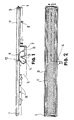
- the reduced height drainage chute of the invention is designed on the basis of an inlet gutter (1) which presents a catch basin (2) in its bottom in the central position, divided into three bodies by means of two partitions (3), with the central body presenting a horizontal outlet (4).
- a drain trap cover (5) fits into the catch basin (2), and presents two skirtings (6) which are introduced intro the lateral bodies without reaching the bottom thereof and which are kept separated thanks to individual tabs (7).
- An array of lugs (8) facilitates the introduction of the screws which secure the usual waterproofing fabric, not represented here.
- a frame (9) Arranged on the inlet gutter (1) is a frame (9) provided with a flange (10), on which rests a grille (11) with a cross-section in "U".
- a conventional aeration valve (12) is provided on the drain trap cover (5).
- the functioning of the inventive chute is as follows. Water collected on the pavement is introduced into the inlet gutter (1) being directed towards the centre from each of its ends, and becoming introduced into the lateral bodies of the catch basin (2) guided by the skirtings (6), in order to overflow on the partitions (3) and be evacuated via the horizontal outlet (4). Once the flow of water has been halted, its level in the drain trap will be that of the partitions (3), ensuring a perfect sealing. If the chute incorporates an aeration valve (12), this will open when a certain depression appears in the horizontal outlet (4), preventing suction of the water stored in the drain trap and preventing the disappearance of the sealing.
- the inlet gutter (1) and the drain trap cover (5) will be made by plastic injection and the frame (9) in stainless steel, though other materials with suitable behaviour would also be feasible.
- the conventional aeration valve (12) can be produced with a lamina structure, spring-loaded ball or any other arrangement that will be thoroughly familiar to the expert on the subject.
Landscapes
- Health & Medical Sciences (AREA)
- Life Sciences & Earth Sciences (AREA)
- Engineering & Computer Science (AREA)
- Hydrology & Water Resources (AREA)
- Public Health (AREA)
- Water Supply & Treatment (AREA)
- Sewage (AREA)
Applications Claiming Priority (1)
| Application Number | Priority Date | Filing Date | Title |
|---|---|---|---|
| ES201130155U ES1074756Y (es) | 2011-02-15 | 2011-02-15 | Canaleta de drenaje de altura reducida con sifon integrado |
Related Parent Applications (1)
| Application Number | Title | Priority Date | Filing Date |
|---|---|---|---|
| ES201130155U Previously-Filed-Application | 2011-02-15 |
Publications (2)
| Publication Number | Publication Date |
|---|---|
| EP2532795A2 true EP2532795A2 (fr) | 2012-12-12 |
| EP2532795A3 EP2532795A3 (fr) | 2015-10-21 |
Family
ID=44063607
Family Applications (1)
| Application Number | Title | Priority Date | Filing Date |
|---|---|---|---|
| EP12000971.7A Withdrawn EP2532795A3 (fr) | 2011-02-15 | 2012-02-15 | Goulotte de drainage de hauteur réduite avec piège à évacuation intégrée |
Country Status (3)
| Country | Link |
|---|---|
| EP (1) | EP2532795A3 (fr) |
| ES (1) | ES1074756Y (fr) |
| RU (1) | RU2012105142A (fr) |
Cited By (4)
| Publication number | Priority date | Publication date | Assignee | Title |
|---|---|---|---|---|
| EP2808458A1 (fr) | 2013-05-29 | 2014-12-03 | WEDI GmbH | Dispositif d'écoulement d'eau pour une douche et élément de sol de douche |
| CN106400938A (zh) * | 2016-12-08 | 2017-02-15 | 中国电子系统工程第四建设有限公司 | 一种侧排式地漏 |
| EP3567169A1 (fr) * | 2018-05-11 | 2019-11-13 | Viega Technology GmbH & Co. KG | Raccord fileté d'évacuation |
| BE1032022B1 (nl) * | 2023-10-02 | 2025-04-28 | Carrodrain | Afvoergootsamenstel, afvoerlichaam voor gebruik in een dergelijk samenstel en reukslot voor gebruik in een dergelijk samenstel |
Families Citing this family (1)
| Publication number | Priority date | Publication date | Assignee | Title |
|---|---|---|---|---|
| ES2555671B1 (es) * | 2014-07-04 | 2016-09-20 | Baroan Rioja, S.L. | Dispositivo de desagüe con orificio de entrada no circular |
Citations (1)
| Publication number | Priority date | Publication date | Assignee | Title |
|---|---|---|---|---|
| EP1854929A1 (fr) | 2006-05-11 | 2007-11-14 | Easy Sanitairy Solutions B.V. | Drain |
Family Cites Families (6)
| Publication number | Priority date | Publication date | Assignee | Title |
|---|---|---|---|---|
| BE858266A (fr) * | 1977-08-31 | 1977-12-16 | Ericson Sture | Installation sanitaire d'evacuation d'eaux usees avec siphon |
| JPS6015826Y2 (ja) * | 1981-05-25 | 1985-05-17 | 株式会社伸晃 | 排水トラップ |
| ES1043234Y (es) * | 1999-06-11 | 2000-05-01 | Jimten Sa | Valvula de aireacion adaptada a una red de evacuacion. |
| NL1025765C2 (nl) * | 2004-03-18 | 2004-09-06 | Jered Nijhof | Goot met stankafsluiter. |
| ITVR20040045A1 (it) * | 2004-04-02 | 2004-07-02 | Dakota Metal Plastic Works Llc | Pozzetto di ispezione con sifone per la raccolta ed il deflusso di liquidi. |
| FR2928156B1 (fr) * | 2008-02-29 | 2014-05-23 | Farhooman Davoudi | Ensemble bonde/siphon d'evacuation compose de plusieurs gardes d'eau |
-
2011
- 2011-02-15 ES ES201130155U patent/ES1074756Y/es not_active Expired - Fee Related
-
2012
- 2012-02-15 RU RU2012105142/03A patent/RU2012105142A/ru not_active Application Discontinuation
- 2012-02-15 EP EP12000971.7A patent/EP2532795A3/fr not_active Withdrawn
Patent Citations (1)
| Publication number | Priority date | Publication date | Assignee | Title |
|---|---|---|---|---|
| EP1854929A1 (fr) | 2006-05-11 | 2007-11-14 | Easy Sanitairy Solutions B.V. | Drain |
Cited By (5)
| Publication number | Priority date | Publication date | Assignee | Title |
|---|---|---|---|---|
| EP2808458A1 (fr) | 2013-05-29 | 2014-12-03 | WEDI GmbH | Dispositif d'écoulement d'eau pour une douche et élément de sol de douche |
| DE102013105542A1 (de) | 2013-05-29 | 2014-12-04 | Wedi Gmbh | Wasserablaufvorrichtung für eine Dusche und Duschbodenelement |
| CN106400938A (zh) * | 2016-12-08 | 2017-02-15 | 中国电子系统工程第四建设有限公司 | 一种侧排式地漏 |
| EP3567169A1 (fr) * | 2018-05-11 | 2019-11-13 | Viega Technology GmbH & Co. KG | Raccord fileté d'évacuation |
| BE1032022B1 (nl) * | 2023-10-02 | 2025-04-28 | Carrodrain | Afvoergootsamenstel, afvoerlichaam voor gebruik in een dergelijk samenstel en reukslot voor gebruik in een dergelijk samenstel |
Also Published As
| Publication number | Publication date |
|---|---|
| ES1074756Y (es) | 2011-09-27 |
| RU2012105142A (ru) | 2013-08-20 |
| EP2532795A3 (fr) | 2015-10-21 |
| ES1074756U (es) | 2011-06-08 |
Similar Documents
| Publication | Publication Date | Title |
|---|---|---|
| EP2532795A2 (fr) | Goulotte de drainage de hauteur réduite avec piège à évacuation intégrée | |
| US20060124519A1 (en) | Drain inlet | |
| US8720723B2 (en) | Modular rainwater storage tank system | |
| EP1854929B1 (fr) | Drain | |
| EP2481332A1 (fr) | Agencement sanitaire, notamment douche à même le sol | |
| DE202012105045U1 (de) | Duschwanne mit einer geneigten Bodenfläche | |
| EP2540923A3 (fr) | Evacuation d'eau avec blocage d'odeur | |
| CA2995031C (fr) | Crepine de plancher et ensemble | |
| KR200444012Y1 (ko) | 배수트랩 | |
| EP2808458A1 (fr) | Dispositif d'écoulement d'eau pour une douche et élément de sol de douche | |
| EP1813731A2 (fr) | Evier de cuisine, en particulier pour des applications domestiques | |
| DE202012103906U1 (de) | Duschwannenanordnung, insbesondere bodengleiche Dusche | |
| KR20160003461U (ko) | 악취 역류방지 기능을 갖춘 배수트랩 | |
| KR102081750B1 (ko) | 하수구용 배수 트랩 | |
| KR20130015991A (ko) | 다수의 분리벽을 구비한 원통형 저수탱크 | |
| KR20140005618A (ko) | 부력식 악취방지 배수트랩 | |
| CA2665085A1 (fr) | Bacs a fleurs en escalier | |
| CN202595890U (zh) | 一种防鼠防臭的排水装置 | |
| JP2013013342A (ja) | 植栽容器 | |
| KR102398648B1 (ko) | 초기우수 배제장치 | |
| CN202706151U (zh) | 新型水漏 | |
| CN203416665U (zh) | 种植箱 | |
| DE102011118676A1 (de) | Gärsaftabscheider | |
| WO2018124981A3 (fr) | Réservoir de stockage d'eau claire à filtre intégré | |
| CN202176016U (zh) | 水沟盖 |
Legal Events
| Date | Code | Title | Description |
|---|---|---|---|
| PUAI | Public reference made under article 153(3) epc to a published international application that has entered the european phase |
Free format text: ORIGINAL CODE: 0009012 |
|
| AK | Designated contracting states |
Kind code of ref document: A2 Designated state(s): AL AT BE BG CH CY CZ DE DK EE ES FI FR GB GR HR HU IE IS IT LI LT LU LV MC MK MT NL NO PL PT RO RS SE SI SK SM TR |
|
| AX | Request for extension of the european patent |
Extension state: BA ME |
|
| PUAL | Search report despatched |
Free format text: ORIGINAL CODE: 0009013 |
|
| AK | Designated contracting states |
Kind code of ref document: A3 Designated state(s): AL AT BE BG CH CY CZ DE DK EE ES FI FR GB GR HR HU IE IS IT LI LT LU LV MC MK MT NL NO PL PT RO RS SE SI SK SM TR |
|
| AX | Request for extension of the european patent |
Extension state: BA ME |
|
| RIC1 | Information provided on ipc code assigned before grant |
Ipc: E03C 1/295 20060101ALN20150917BHEP Ipc: E03F 5/04 20060101AFI20150917BHEP |
|
| 17P | Request for examination filed |
Effective date: 20160126 |
|
| RBV | Designated contracting states (corrected) |
Designated state(s): AL AT BE BG CH CY CZ DE DK EE ES FI FR GB GR HR HU IE IS IT LI LT LU LV MC MK MT NL NO PL PT RO RS SE SI SK SM TR |
|
| 17Q | First examination report despatched |
Effective date: 20160809 |
|
| STAA | Information on the status of an ep patent application or granted ep patent |
Free format text: STATUS: THE APPLICATION IS DEEMED TO BE WITHDRAWN |
|
| 18D | Application deemed to be withdrawn |
Effective date: 20170221 |