EP2532818A2 - Ferrure de meuble pour un élément de meuble mobile - Google Patents
Ferrure de meuble pour un élément de meuble mobile Download PDFInfo
- Publication number
- EP2532818A2 EP2532818A2 EP12000462A EP12000462A EP2532818A2 EP 2532818 A2 EP2532818 A2 EP 2532818A2 EP 12000462 A EP12000462 A EP 12000462A EP 12000462 A EP12000462 A EP 12000462A EP 2532818 A2 EP2532818 A2 EP 2532818A2
- Authority
- EP
- European Patent Office
- Prior art keywords
- furniture
- fastening
- fitting according
- expansion element
- furniture fitting
- Prior art date
- Legal status (The legal status is an assumption and is not a legal conclusion. Google has not performed a legal analysis and makes no representation as to the accuracy of the status listed.)
- Granted
Links
Images

Classifications
-
- F—MECHANICAL ENGINEERING; LIGHTING; HEATING; WEAPONS; BLASTING
- F16—ENGINEERING ELEMENTS AND UNITS; GENERAL MEASURES FOR PRODUCING AND MAINTAINING EFFECTIVE FUNCTIONING OF MACHINES OR INSTALLATIONS; THERMAL INSULATION IN GENERAL
- F16B—DEVICES FOR FASTENING OR SECURING CONSTRUCTIONAL ELEMENTS OR MACHINE PARTS TOGETHER, e.g. NAILS, BOLTS, CIRCLIPS, CLAMPS, CLIPS OR WEDGES; JOINTS OR JOINTING
- F16B12/00—Jointing of furniture or the like, e.g. hidden from exterior
- F16B12/10—Jointing of furniture or the like, e.g. hidden from exterior using pegs, bolts, tenons, clamps, clips, or the like
- F16B12/12—Jointing of furniture or the like, e.g. hidden from exterior using pegs, bolts, tenons, clamps, clips, or the like for non-metal furniture parts, e.g. made of wood, of plastics
- F16B12/20—Jointing of furniture or the like, e.g. hidden from exterior using pegs, bolts, tenons, clamps, clips, or the like for non-metal furniture parts, e.g. made of wood, of plastics using clamps, clips, wedges, sliding bolts, or the like
- F16B12/2009—Jointing of furniture or the like, e.g. hidden from exterior using pegs, bolts, tenons, clamps, clips, or the like for non-metal furniture parts, e.g. made of wood, of plastics using clamps, clips, wedges, sliding bolts, or the like actuated by rotary motion
-
- A—HUMAN NECESSITIES
- A47—FURNITURE; DOMESTIC ARTICLES OR APPLIANCES; COFFEE MILLS; SPICE MILLS; SUCTION CLEANERS IN GENERAL
- A47B—TABLES; DESKS; OFFICE FURNITURE; CABINETS; DRAWERS; GENERAL DETAILS OF FURNITURE
- A47B95/00—Fittings for furniture
-
- E—FIXED CONSTRUCTIONS
- E05—LOCKS; KEYS; WINDOW OR DOOR FITTINGS; SAFES
- E05D—HINGES OR SUSPENSION DEVICES FOR DOORS, WINDOWS OR WINGS
- E05D5/00—Construction of single parts, e.g. the parts for attachment
- E05D5/02—Parts for attachment, e.g. flaps
- E05D5/08—Parts for attachment, e.g. flaps of cylindrical shape
-
- E—FIXED CONSTRUCTIONS
- E05—LOCKS; KEYS; WINDOW OR DOOR FITTINGS; SAFES
- E05D—HINGES OR SUSPENSION DEVICES FOR DOORS, WINDOWS OR WINGS
- E05D7/00—Hinges or pivots of special construction
- E05D7/12—Hinges or pivots of special construction to allow easy detachment of the hinge from the wing or the frame
- E05D7/123—Hinges or pivots of special construction to allow easy detachment of the hinge from the wing or the frame specially adapted for cabinets or furniture
-
- E—FIXED CONSTRUCTIONS
- E05—LOCKS; KEYS; WINDOW OR DOOR FITTINGS; SAFES
- E05Y—INDEXING SCHEME ASSOCIATED WITH SUBCLASSES E05D AND E05F, RELATING TO CONSTRUCTION ELEMENTS, ELECTRIC CONTROL, POWER SUPPLY, POWER SIGNAL OR TRANSMISSION, USER INTERFACES, MOUNTING OR COUPLING, DETAILS, ACCESSORIES, AUXILIARY OPERATIONS NOT OTHERWISE PROVIDED FOR, APPLICATION THEREOF
- E05Y2600/00—Mounting or coupling arrangements for elements provided for in this subclass
- E05Y2600/50—Mounting methods; Positioning
- E05Y2600/504—Expansion
-
- E—FIXED CONSTRUCTIONS
- E05—LOCKS; KEYS; WINDOW OR DOOR FITTINGS; SAFES
- E05Y—INDEXING SCHEME ASSOCIATED WITH SUBCLASSES E05D AND E05F, RELATING TO CONSTRUCTION ELEMENTS, ELECTRIC CONTROL, POWER SUPPLY, POWER SIGNAL OR TRANSMISSION, USER INTERFACES, MOUNTING OR COUPLING, DETAILS, ACCESSORIES, AUXILIARY OPERATIONS NOT OTHERWISE PROVIDED FOR, APPLICATION THEREOF
- E05Y2600/00—Mounting or coupling arrangements for elements provided for in this subclass
- E05Y2600/50—Mounting methods; Positioning
- E05Y2600/52—Toolless
-
- E—FIXED CONSTRUCTIONS
- E05—LOCKS; KEYS; WINDOW OR DOOR FITTINGS; SAFES
- E05Y—INDEXING SCHEME ASSOCIATED WITH SUBCLASSES E05D AND E05F, RELATING TO CONSTRUCTION ELEMENTS, ELECTRIC CONTROL, POWER SUPPLY, POWER SIGNAL OR TRANSMISSION, USER INTERFACES, MOUNTING OR COUPLING, DETAILS, ACCESSORIES, AUXILIARY OPERATIONS NOT OTHERWISE PROVIDED FOR, APPLICATION THEREOF
- E05Y2900/00—Application of doors, windows, wings or fittings thereof
- E05Y2900/20—Application of doors, windows, wings or fittings thereof for furniture, e.g. cabinets
-
- F—MECHANICAL ENGINEERING; LIGHTING; HEATING; WEAPONS; BLASTING
- F16—ENGINEERING ELEMENTS AND UNITS; GENERAL MEASURES FOR PRODUCING AND MAINTAINING EFFECTIVE FUNCTIONING OF MACHINES OR INSTALLATIONS; THERMAL INSULATION IN GENERAL
- F16B—DEVICES FOR FASTENING OR SECURING CONSTRUCTIONAL ELEMENTS OR MACHINE PARTS TOGETHER, e.g. NAILS, BOLTS, CIRCLIPS, CLAMPS, CLIPS OR WEDGES; JOINTS OR JOINTING
- F16B13/00—Dowels or other devices fastened in walls or the like by inserting them in holes made therein for that purpose
- F16B13/04—Dowels or other devices fastened in walls or the like by inserting them in holes made therein for that purpose with parts gripping in the hole or behind the reverse side of the wall after inserting from the front
- F16B13/06—Dowels or other devices fastened in walls or the like by inserting them in holes made therein for that purpose with parts gripping in the hole or behind the reverse side of the wall after inserting from the front combined with expanding sleeve
- F16B13/063—Dowels or other devices fastened in walls or the like by inserting them in holes made therein for that purpose with parts gripping in the hole or behind the reverse side of the wall after inserting from the front combined with expanding sleeve by the use of an expander
- F16B13/065—Dowels or other devices fastened in walls or the like by inserting them in holes made therein for that purpose with parts gripping in the hole or behind the reverse side of the wall after inserting from the front combined with expanding sleeve by the use of an expander fastened by extracting the screw, nail or the like
Definitions
- the invention relates to a furniture fitting for a movable furniture part, in particular door, flap, drawer or the like, with at least one fitting part with fastening elements, which are assigned to the movable furniture part or on a furniture body of a furniture fitted with the movable furniture part mounting holes and inserted into this wherein the fastening elements in each case at least one spreading element is assigned, which is radially alssp Schwarzbar via a relatively acting between the fastening element and spreading fastening movement and in a clamping position thereby achievable with a wall of the mounting hole can be clamped.
- a furniture fitting of this kind is for example from the DE 195 27 600 C5 known.
- the furniture fitting disclosed therein has a fitting part which can be fastened to a furniture with two fastening pins which project from its fastening surface facing the surface of the furniture piece wall and can be inserted into an associated fastening hole in the wall.
- In the hollow interior of the mounting pins is in each case a displaceable in the journal longitudinal direction and the fixing pin thereby - depending on the adjustment - spreading or relaxing expander, which has a tapered in the direction of fitting spreader.
- the spreader goes into a through the Fastening pin extending therethrough, at the end of which is arranged on a pressure surface of the fitting part, provided with a handle and the expansion element is adjusted upon actuation actuating element. When tightening by actuation of the actuating element of the spreader is pushed upwards, whereby the ends of the fastening pin are spread open, so that there is a tension with the wall of the mounting hole.
- the object of the invention is to provide a furniture fitting of the type mentioned above, which offers a large variability in the attachment to a movable furniture part or on a furniture body, with the necessary parts for the attachment are inexpensive to manufacture.
- the furniture fitting according to the invention is characterized in that the at least one expansion element has a passage opening, via which it is mounted on the associated fastening element is threaded and there is mounted so displaceable relative to these that the radial spreading and tension with the wall of the mounting hole at the initiation of the fastening movement on a reduction of the axial dimension of the expansion element can be achieved.
- the at least one expansion element can be threaded onto the fastening element.
- the expansion element is thus a separate component from the fastening element, which allows different circumstances in the assembly of the furniture fitting on the movable furniture part or the furniture body by different number or different shape of spreading that are threaded onto the fastener, take into account. This results in a high variability in the attachment of the furniture fitting.
- Another difference with respect to the prior art is that the radial spread and stress is accompanied by a reduction in the axial dimension of the expansion element.
- gaps between the associated mounting hole and the fastener can be optimally balanced and depending on the configuration of the mounting hole and the expansion element can form a positive and / or non-positive connection between the wall of the mounting hole and the fastener during bracing.
- the furniture fitting according to the invention is particularly suitable as a quick fastening, especially for materials with low strength, such as honeycomb panels, light chipboard, etc.
- the movable or movable furniture part for example, via a guide unit movably on a furniture body movably received drawer or an extract or a relative to a furniture body pivoting door, flap or the like.
- the fitting can be used as a hinge, Flap fitting or guide unit of an extract or a drawer be designed.
- the at least one expansion element made of deformable material which is deformable under the action of the fastening movement in the clamping position.
- the expansion element has a curvature, whose bulge height extending in the axial direction can be reduced under the effect of the fastening movement with radial spreading.
- the expansion element with such a curvature can thus be "flattened” under the action of the fastening movement, while at the same time radially spreads.
- the expansion element is designed as a U-like curved ring body in cross section, with a penetrated by the passage opening base portion and two of the base portion, preferably in divergent manner projecting leg portions.
- the cross-sectional shape of the expansion element could also be referred to as saddle-like.
- the spreader element is O-shaped in plan view, in particular oval or circular.
- the passage opening sits centrally.
- a plurality of expansion elements are arranged one behind the other in the axial direction on the associated fastening element to form a spreading element stack.
- the number of threaded spreader elements is arbitrary, whereby an adaptation to different depths of the mounting holes can be carried out in a simple and fast manner.
- adjacent spreading elements are either aligned in the same direction to each other, whereby adjacent base portions interlock or twisted aligned with each other, whereby the base portion of a spreader comes to lie on the leg portions of the adjacent expansion element.
- the at least one expansion element is constructed in several parts, with Spreizelement timing which are lined up in the axial direction one behind the other on the associated fastener, wherein the Spreizelementmaschine facing each other sliding surfaces which are aligned such that they under the effect of the fastening movement to reach the clamping position in the direction radially outward slide on each other.
- the Spreizelementmaschine may for example consist of under the action of the fastening movement substantially non-deformable material.
- the Spreizelementmaschine are each configured as interspersed by the passage opening cylinder body, wherein the respective sliding surfaces are obliquely, in particular at an angle of approximately 45 °, aligned with respect to the axial direction.
- the fastening element is designed as a centering pin which is movably mounted on the fitting part in the axial direction via a manually actuable actuating element and presses the threading elements threaded onto a shank portion of the centering pin into the clamping position when the fastening movement is initiated via the actuating element.
- the actuating element may be, for example, a clamping lever which can be actuated manually and, for example, causes an axial displacement of the actuating element in the associated fastening hole with the aid of an eccentric, whereby a radial spreading of the expanding element takes place during the fastening or clamping movement.
- the fastening element at its end remote from the fitting part has a fixing element designed in particular as an annular body for the axial fixing of the at least one expansion element.
- the fixing element is detachably connected to the shaft portion, whereby the at least one expansion element initially threaded and then the fixing element can be attached to the shaft portion.
- elastic spreading elements it would be possible in particular with elastic spreading elements to widen the passage opening so far that it fits over the larger diameter fixing and snaps back into its original shape after passing the fixing.
- the invention further comprises a piece of furniture, with a movable furniture part, such as flap, door or drawer, which is equipped with a furniture fitting according to one of claims 1 to 15.
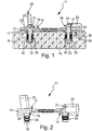
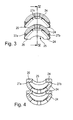
- the Figures 1 and 2 show a first embodiment of the furniture fitting according to the invention 11.
- the furniture fitting 11 may for example be designed as a front panel mounting bracket, which is suitable for tool-free, quick and easy installation - and disassembly - a front panel of a drawer on the drawer.
- the furniture fitting 11 is designed as a furniture hinge, with which a movable furniture part in the form of, for example, a door leaf can be attached to the furniture body.
- an embodiment of the furniture fitting 11 in the form of a flap fitting would be conceivable that connects a movable furniture part 15 in the form of a furniture flap with the furniture body.
- the invention can be realized in all the aforementioned embodiments of the furniture fitting 11 as well as in other, not mentioned embodiments and will be described below purely by way of example with reference to a designed as a furniture hinge furniture fitting 11.
- the furniture fitting 11 has a fitting 12, which is formed in the example as a carcass or door stop part of a furniture hinge.
- the door leaf stop member could be a hinge cup of a cup hinge formed as furniture hinge.
- the fitting part 12 has a mounting plate 13, the underside of which forms a contact surface 14, which is brought into contact with the movable furniture part 15 during assembly, ie in the example with a door leaf or the furniture body.
- the fitting part 12 further comprises at least one pin-like fastening element 16, wherein in the example two such fastening elements 16 are shown.
- the pin-like fastening element 16 is inserted during assembly in a trained on the movable furniture part 15 mounting hole 40 and anchored there in the manner described below.
- the pin-like fastening element 16 has a base portion 17 which passes through the mounting plate 13.
- the base portion 17 merges into a smaller-diameter shank portion 18, at the free end of which a fixing element 19 designed as an annular body is located.
- the ring-body-like fixing element 19, which could also be referred to as a fixing ring, is detachably connected to the shaft portion 18. For example, it can be screwed onto the shaft section 18 by threads formed complementarily on shaft section 18 and fixing element.
- the underside of the fixing element 19, together with the free end face of the shaft portion 18, forms a stop surface 20 which abuts against the bottom of the fastening hole 40 designed as a blind hole.
- a bearing axis 21 to which an actuating element 22 is pivotally mounted in the form of a clamping lever.
- the cocking lever can be adjusted manually between an on in FIG. 1 right clamping element shown pivoting position and a loose position pivot.
- the actuating element 22 has in the region of the bearing axis 21 an eccentric part 23, which is supported on the upper side of the mounting plate 13.
- Lose position shown on the left operating member 22 is the bearing axis 21 closer portion of the eccentric portion 23 at the top of the mounting plate 13 on. If you swing the clamping lever from the release position to the in FIG. 1 the tensioning position shown on the right fastening element 16, the area of the eccentric section 23 located farther away from the bearing axis 21 lies on the upper side of the mounting plate 13, as a result of which the fastening element 16 assumes a raised position.
- the fastening elements 16 are each associated with at least one expansion element 24, which can be braced radially by means of a fastening movement acting between fastening element 16 and expansion element 24, ie by tensioning the tensioning lever, and can be clamped in a clamping position achievable thereby with a wall of the fastening hole 40.
- the expansion element 24 consists of elastically deformable material, for example metal, in particular steel, or plastic.
- the spreader 24 has a characteristic shape with a curvature. The bulging height of the curvature extending in the axial direction can be reduced under the effect of the fastening movement with radial spreading.
- the expansion element 24 is designed as a ring body and has a particular centrally located passage opening 25.
- the expansion element 24 is U-shaped in cross section.
- a penetrated by the passage opening 25 base portion 26 and two of the base portion 26, preferably in divergent manner projecting leg portions 27a, 27b are provided.
- the spreader 24 could also be referred to as saddle-like.
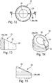
- the expansion element 24 is O-shaped in plan view. It shows FIG. 9 an unspread starting position, while this shape changes upon radial spreading into an oval.
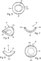
- each fastening element 16 a plurality of spreading elements 24 are assigned, which are lined up in the axial direction one behind the other on the associated fastener 16 to a spreading element stack.
- the stacking height of a spreading element stack can be varied by different orientation of adjacent spreading elements 24 relative to each other.
- the two upper spreading elements 90 ° offset from each other, whereby the base portion 26 of the one expanding element 24 comes to rest on the leg portions 27a, 27b of the other expansion element 24.
- the axially extending height of these two stacked spreading elements 24 is, for example, significantly larger than in the case that the two spreading elements 24 are rectified or aligned in the same direction in the same direction. When aligned in the same direction come the adjacent base portions 26 and the adjacent leg portions 27a, 27b of the two spreading elements to each other, resulting in a compact stack.
- FIG. 3 Another variant is the stack that passes through the two in FIG. 3 is shown formed central spreading elements 24.
- the two spreading elements are aligned in the opposite position to each other, whereby the two lower sides of the base portions 26 come to rest on each other, resulting in an even greater stack height.
- An important aspect is that regardless of the number and orientation of stacked spreading elements always, as in FIG. 5 represented, one In plan view, substantially O-shaped or circular shape results, whereby the insertion into a round in cross-section mounting hole 40 on the movable furniture part 25 is possible in a simple manner.
- the spreading elements 24 are first threaded in the required number and orientation to the manhole section 18 of the pin-like fastening element 16.
- the ring-body-like fixing element is removed from the shaft portion 18 and is fastened to the shaft portion 18 again after the threading of the spreading elements 24.
- the equipped with spreading elements 24 fasteners 16 are inserted into the space provided for mounting holes 40 on the movable furniture part 15 until the contact surface 14 comes to rest on the underside of the mounting plate 13 on the mounting surface of the movable furniture part 15.
- the actuating element 22 in the form of the clamping lever in its release position.
- the spreading elements 24 are mounted loosely on the shaft portion 18, but are fixed in the axial direction at the bottom by the fixing element 19 and at the top by the larger diameter base portion 17 of the fastening element 16.
- the spreading elements 24 are mounted relative to the shaft portion 18 so as to be relatively displaceable. If the clamping lever is then pivoted into its clamping position, then the fastening element 16 is pressed by the eccentric portion 23 on the clamping lever upwards.
- the spreading elements 24 remain in position and are radially spread apart by the fixing element 19 and flattened at the same time, so that there is a reduction in the axial dimension of the expansion element 24 and the expansion element stack. This process of radial Aufspreizens while reducing the axial dimension leads to a Bracing with the wall of the mounting hole 40.
- the fastener 16 is now anchored in the mounting hole 40.
- FIGS. 10 to 15 show a second embodiment of the furniture fitting according to the invention.
- Fitting part 12, mounting plate 13, fastener 16 and actuator 22 are constructed substantially in an identical manner to the embodiment described above, so that will not be discussed in detail.
- the second embodiment thus differs in the embodiment of the spreading elements 24 from the first embodiment described above.
- the spreading elements 24 of the second embodiment are constructed in several parts and each have at least two, in particular exactly two, Spreizelementmaschine 28a, 28b, which are lined up in the axial direction one behind the other on the shaft portion 18 of the fastener.
- the Spreizelementmaschine 28, 28a, 28b respectively as penetrated by the passage opening 25 cylinder body, which are chamfered on one end side.
- the Spreizelementmaschine 28a, 28b each still have a running in the radial direction and the wall of the cylinder body passing through slot opening 30.
- the spreading elements 24 thus the Spreizelementmaschine 28a, 28b, from under the action of the fastening movement in Made essentially non-deformable material.
- metal or plastic can be used.
- the two Spreizelementmaschine 28a, 28b initially threaded onto the shaft portion 18.
- the fixing element 19 is in turn received by the shaft portion 28 to allow threading.
- the Spreizelementmaschine 28a, 28b are threaded in such a way that the sliding surface 29 come to rest on each other.
- the equipped with the spreading elements 24 fasteners are inserted again in the associated mounting hole 40 on the movable furniture part 15.
- the clamping lever is pivoted into the clamping position, wherein the fastening element, as already described, is pulled up in the axial direction to the mounting plate 13 towards.
- the fixing element 19 engages the spreading elements 24 and presses the two sliding surfaces 29 against each other, which slide on each other. Due to the radial slot opening 30 at the two Spreizelement turnover 28a, 28b, a radial displacement of the Spreizelementmaschine 28a, 28b, so a radial spreading, possible, while also the axial dimension of the two Spreizelement constitution 28a, 28b existing spreader 24 is reduced. As with the first embodiment described above, it comes to a strain with the wall of the mounting hole 40, whereby the fastener 16 is anchored in the mounting hole 40.
Landscapes
- Engineering & Computer Science (AREA)
- Mechanical Engineering (AREA)
- General Engineering & Computer Science (AREA)
- Hinges (AREA)
- Connection Of Plates (AREA)
- Furniture Connections (AREA)
Applications Claiming Priority (1)
| Application Number | Priority Date | Filing Date | Title |
|---|---|---|---|
| DE202011101542U DE202011101542U1 (de) | 2011-06-08 | 2011-06-08 | Möbelbeschlag für ein bewegbares Möbelteil |
Publications (3)
| Publication Number | Publication Date |
|---|---|
| EP2532818A2 true EP2532818A2 (fr) | 2012-12-12 |
| EP2532818A3 EP2532818A3 (fr) | 2016-05-18 |
| EP2532818B1 EP2532818B1 (fr) | 2018-03-07 |
Family
ID=45560667
Family Applications (1)
| Application Number | Title | Priority Date | Filing Date |
|---|---|---|---|
| EP12000462.7A Not-in-force EP2532818B1 (fr) | 2011-06-08 | 2012-01-26 | Ferrure pour un élément de meuble mobile |
Country Status (2)
| Country | Link |
|---|---|
| EP (1) | EP2532818B1 (fr) |
| DE (1) | DE202011101542U1 (fr) |
Families Citing this family (3)
| Publication number | Priority date | Publication date | Assignee | Title |
|---|---|---|---|---|
| DE102013205872A1 (de) * | 2013-04-03 | 2014-10-09 | Simex Filterpressen und Wassertechnik GmbH & Co. KG | Filterpresse |
| DE102017102786B4 (de) | 2017-02-13 | 2019-02-14 | Ass-Einrichtungssysteme Gmbh | Verbindungsbeschlag |
| DE102024124583A1 (de) * | 2024-08-28 | 2026-03-05 | Paul Hettich Gmbh & Co. Kg | Befestigungsmittel zur Befestigung eines Funktionselementes an einem Bauteil |
Citations (2)
| Publication number | Priority date | Publication date | Assignee | Title |
|---|---|---|---|---|
| DE19527600C2 (de) | 1995-07-28 | 1997-09-04 | Lautenschlaeger Mepla Werke | Möbelbeschlag |
| AT407415B (de) | 1993-02-08 | 2001-03-26 | Blum Gmbh Julius | Möbelbeschlag |
Family Cites Families (4)
| Publication number | Priority date | Publication date | Assignee | Title |
|---|---|---|---|---|
| DE4119047C2 (de) * | 1991-03-27 | 1998-12-10 | Lautenschlaeger Mepla Werke | Kunststoff-Haltezapfen, insbesondere für Möbelbeschläge |
| AT397699B (de) * | 1992-01-20 | 1994-06-27 | Blum Gmbh Julius | Dübelanordnung |
| AT403499B (de) * | 1992-06-24 | 1998-02-25 | Blum Gmbh Julius | Dübelanordnung, insbesondere zur befestigung von möbelbeschlägen |
| US8137039B2 (en) * | 2009-08-06 | 2012-03-20 | King Slide Works Co., Ltd. | Connecting fitting |
-
2011
- 2011-06-08 DE DE202011101542U patent/DE202011101542U1/de not_active Expired - Lifetime
-
2012
- 2012-01-26 EP EP12000462.7A patent/EP2532818B1/fr not_active Not-in-force
Patent Citations (2)
| Publication number | Priority date | Publication date | Assignee | Title |
|---|---|---|---|---|
| AT407415B (de) | 1993-02-08 | 2001-03-26 | Blum Gmbh Julius | Möbelbeschlag |
| DE19527600C2 (de) | 1995-07-28 | 1997-09-04 | Lautenschlaeger Mepla Werke | Möbelbeschlag |
Also Published As
| Publication number | Publication date |
|---|---|
| EP2532818B1 (fr) | 2018-03-07 |
| EP2532818A3 (fr) | 2016-05-18 |
| DE202011101542U1 (de) | 2012-09-13 |
Similar Documents
| Publication | Publication Date | Title |
|---|---|---|
| DE60208218T2 (de) | Vorrichtung und verfahren zur lösbaren verbindung aneinanderstossender lasttragender teile und zugglied zur verwendung zur herstellung der vorrichtung | |
| DE19505311C2 (de) | Befestigungsanordnung von Beschlägen, insbesondere Möbelbeschlägen an Möbelstücken | |
| EP1918596B1 (fr) | Rivet aveugle et son utilisation | |
| DE1750663C3 (de) | Ankerschraube | |
| DE1204024B (de) | Befestigungsvorrichtung | |
| EP0464574A1 (fr) | Elément de fixation | |
| DE4133478A1 (de) | Befestigungseinrichtung, insbesondere zum befestigen einer verkleidung an einer unterstruktur | |
| EP2834528A1 (fr) | Rivet autopoinçonneur pourvu d'un élément plat préperforé, procédé de fabrication ainsi que procédé d'assemblage | |
| DE1500864A1 (de) | Blind-Niet | |
| EP3916182B1 (fr) | Cheville pour la fixation de pièces de ferrure | |
| EP2014171B1 (fr) | Plateau de cuisson | |
| DE102009019345A1 (de) | Befestigungselement | |
| EP3359826B1 (fr) | Ferrure de meuble | |
| EP2532818B1 (fr) | Ferrure pour un élément de meuble mobile | |
| DE2723614B2 (de) | Befestigungsvorrichtung mit einer Schraube und einer Schnellspannmutter | |
| DE2754910A1 (de) | Befestigungsvorrichtung zum einsetzen in eine aufnahme in einer wandung oder zum verbinden von aufnahmen aufweisenden elementen | |
| DE19531016C2 (de) | Verbindungselement, nach Art eines Niets | |
| DE2803711C2 (fr) | ||
| DE19607516C2 (de) | Befestigungselement | |
| EP1257185B1 (fr) | Element de raccordement pour un meuble, notamment pour une table | |
| DE2133598A1 (de) | Aufweitwerkzeug | |
| DE19943727C1 (de) | Spreizniet | |
| DE19950745B4 (de) | Montageelement mit einem Verbindungszapfen und einer Befestigungshülse | |
| EP2075121A1 (fr) | Plaque améliorée en verre multicouche, notamment en verre de sécurité stratifié, et procédé de fabrication de celle-ci | |
| DE4404698A1 (de) | Spreizdübel |
Legal Events
| Date | Code | Title | Description |
|---|---|---|---|
| PUAI | Public reference made under article 153(3) epc to a published international application that has entered the european phase |
Free format text: ORIGINAL CODE: 0009012 |
|
| AK | Designated contracting states |
Kind code of ref document: A2 Designated state(s): AL AT BE BG CH CY CZ DE DK EE ES FI FR GB GR HR HU IE IS IT LI LT LU LV MC MK MT NL NO PL PT RO RS SE SI SK SM TR |
|
| AX | Request for extension of the european patent |
Extension state: BA ME |
|
| PUAL | Search report despatched |
Free format text: ORIGINAL CODE: 0009013 |
|
| AK | Designated contracting states |
Kind code of ref document: A3 Designated state(s): AL AT BE BG CH CY CZ DE DK EE ES FI FR GB GR HR HU IE IS IT LI LT LU LV MC MK MT NL NO PL PT RO RS SE SI SK SM TR |
|
| AX | Request for extension of the european patent |
Extension state: BA ME |
|
| RIC1 | Information provided on ipc code assigned before grant |
Ipc: E05D 7/12 20060101ALI20160414BHEP Ipc: E05D 5/02 20060101AFI20160414BHEP |
|
| STAA | Information on the status of an ep patent application or granted ep patent |
Free format text: STATUS: REQUEST FOR EXAMINATION WAS MADE |
|
| 17P | Request for examination filed |
Effective date: 20161118 |
|
| RBV | Designated contracting states (corrected) |
Designated state(s): AL AT BE BG CH CY CZ DE DK EE ES FI FR GB GR HR HU IE IS IT LI LT LU LV MC MK MT NL NO PL PT RO RS SE SI SK SM TR |
|
| GRAP | Despatch of communication of intention to grant a patent |
Free format text: ORIGINAL CODE: EPIDOSNIGR1 |
|
| STAA | Information on the status of an ep patent application or granted ep patent |
Free format text: STATUS: GRANT OF PATENT IS INTENDED |
|
| INTG | Intention to grant announced |
Effective date: 20170928 |
|
| GRAS | Grant fee paid |
Free format text: ORIGINAL CODE: EPIDOSNIGR3 |
|
| GRAA | (expected) grant |
Free format text: ORIGINAL CODE: 0009210 |
|
| STAA | Information on the status of an ep patent application or granted ep patent |
Free format text: STATUS: THE PATENT HAS BEEN GRANTED |
|
| AK | Designated contracting states |
Kind code of ref document: B1 Designated state(s): AL AT BE BG CH CY CZ DE DK EE ES FI FR GB GR HR HU IE IS IT LI LT LU LV MC MK MT NL NO PL PT RO RS SE SI SK SM TR |
|
| REG | Reference to a national code |
Ref country code: GB Ref legal event code: FG4D Free format text: NOT ENGLISH |
|
| REG | Reference to a national code |
Ref country code: CH Ref legal event code: EP Ref country code: AT Ref legal event code: REF Ref document number: 976732 Country of ref document: AT Kind code of ref document: T Effective date: 20180315 |
|
| REG | Reference to a national code |
Ref country code: IE Ref legal event code: FG4D Free format text: LANGUAGE OF EP DOCUMENT: GERMAN |
|
| REG | Reference to a national code |
Ref country code: DE Ref legal event code: R096 Ref document number: 502012012276 Country of ref document: DE |
|
| REG | Reference to a national code |
Ref country code: NL Ref legal event code: MP Effective date: 20180307 |
|
| REG | Reference to a national code |
Ref country code: LT Ref legal event code: MG4D |
|
| PG25 | Lapsed in a contracting state [announced via postgrant information from national office to epo] |
Ref country code: ES Free format text: LAPSE BECAUSE OF FAILURE TO SUBMIT A TRANSLATION OF THE DESCRIPTION OR TO PAY THE FEE WITHIN THE PRESCRIBED TIME-LIMIT Effective date: 20180307 Ref country code: LT Free format text: LAPSE BECAUSE OF FAILURE TO SUBMIT A TRANSLATION OF THE DESCRIPTION OR TO PAY THE FEE WITHIN THE PRESCRIBED TIME-LIMIT Effective date: 20180307 Ref country code: CY Free format text: LAPSE BECAUSE OF FAILURE TO SUBMIT A TRANSLATION OF THE DESCRIPTION OR TO PAY THE FEE WITHIN THE PRESCRIBED TIME-LIMIT Effective date: 20180307 Ref country code: HR Free format text: LAPSE BECAUSE OF FAILURE TO SUBMIT A TRANSLATION OF THE DESCRIPTION OR TO PAY THE FEE WITHIN THE PRESCRIBED TIME-LIMIT Effective date: 20180307 Ref country code: FI Free format text: LAPSE BECAUSE OF FAILURE TO SUBMIT A TRANSLATION OF THE DESCRIPTION OR TO PAY THE FEE WITHIN THE PRESCRIBED TIME-LIMIT Effective date: 20180307 Ref country code: NO Free format text: LAPSE BECAUSE OF FAILURE TO SUBMIT A TRANSLATION OF THE DESCRIPTION OR TO PAY THE FEE WITHIN THE PRESCRIBED TIME-LIMIT Effective date: 20180607 |
|
| PG25 | Lapsed in a contracting state [announced via postgrant information from national office to epo] |
Ref country code: BG Free format text: LAPSE BECAUSE OF FAILURE TO SUBMIT A TRANSLATION OF THE DESCRIPTION OR TO PAY THE FEE WITHIN THE PRESCRIBED TIME-LIMIT Effective date: 20180607 Ref country code: RS Free format text: LAPSE BECAUSE OF FAILURE TO SUBMIT A TRANSLATION OF THE DESCRIPTION OR TO PAY THE FEE WITHIN THE PRESCRIBED TIME-LIMIT Effective date: 20180307 Ref country code: GR Free format text: LAPSE BECAUSE OF FAILURE TO SUBMIT A TRANSLATION OF THE DESCRIPTION OR TO PAY THE FEE WITHIN THE PRESCRIBED TIME-LIMIT Effective date: 20180608 Ref country code: SE Free format text: LAPSE BECAUSE OF FAILURE TO SUBMIT A TRANSLATION OF THE DESCRIPTION OR TO PAY THE FEE WITHIN THE PRESCRIBED TIME-LIMIT Effective date: 20180307 Ref country code: LV Free format text: LAPSE BECAUSE OF FAILURE TO SUBMIT A TRANSLATION OF THE DESCRIPTION OR TO PAY THE FEE WITHIN THE PRESCRIBED TIME-LIMIT Effective date: 20180307 |
|
| PG25 | Lapsed in a contracting state [announced via postgrant information from national office to epo] |
Ref country code: MT Free format text: LAPSE BECAUSE OF FAILURE TO SUBMIT A TRANSLATION OF THE DESCRIPTION OR TO PAY THE FEE WITHIN THE PRESCRIBED TIME-LIMIT Effective date: 20180307 |
|
| PG25 | Lapsed in a contracting state [announced via postgrant information from national office to epo] |
Ref country code: RO Free format text: LAPSE BECAUSE OF FAILURE TO SUBMIT A TRANSLATION OF THE DESCRIPTION OR TO PAY THE FEE WITHIN THE PRESCRIBED TIME-LIMIT Effective date: 20180307 Ref country code: NL Free format text: LAPSE BECAUSE OF FAILURE TO SUBMIT A TRANSLATION OF THE DESCRIPTION OR TO PAY THE FEE WITHIN THE PRESCRIBED TIME-LIMIT Effective date: 20180307 Ref country code: PL Free format text: LAPSE BECAUSE OF FAILURE TO SUBMIT A TRANSLATION OF THE DESCRIPTION OR TO PAY THE FEE WITHIN THE PRESCRIBED TIME-LIMIT Effective date: 20180307 Ref country code: AL Free format text: LAPSE BECAUSE OF FAILURE TO SUBMIT A TRANSLATION OF THE DESCRIPTION OR TO PAY THE FEE WITHIN THE PRESCRIBED TIME-LIMIT Effective date: 20180307 Ref country code: EE Free format text: LAPSE BECAUSE OF FAILURE TO SUBMIT A TRANSLATION OF THE DESCRIPTION OR TO PAY THE FEE WITHIN THE PRESCRIBED TIME-LIMIT Effective date: 20180307 |
|
| PG25 | Lapsed in a contracting state [announced via postgrant information from national office to epo] |
Ref country code: SM Free format text: LAPSE BECAUSE OF FAILURE TO SUBMIT A TRANSLATION OF THE DESCRIPTION OR TO PAY THE FEE WITHIN THE PRESCRIBED TIME-LIMIT Effective date: 20180307 Ref country code: SK Free format text: LAPSE BECAUSE OF FAILURE TO SUBMIT A TRANSLATION OF THE DESCRIPTION OR TO PAY THE FEE WITHIN THE PRESCRIBED TIME-LIMIT Effective date: 20180307 Ref country code: CZ Free format text: LAPSE BECAUSE OF FAILURE TO SUBMIT A TRANSLATION OF THE DESCRIPTION OR TO PAY THE FEE WITHIN THE PRESCRIBED TIME-LIMIT Effective date: 20180307 |
|
| REG | Reference to a national code |
Ref country code: DE Ref legal event code: R097 Ref document number: 502012012276 Country of ref document: DE |
|
| PG25 | Lapsed in a contracting state [announced via postgrant information from national office to epo] |
Ref country code: PT Free format text: LAPSE BECAUSE OF FAILURE TO SUBMIT A TRANSLATION OF THE DESCRIPTION OR TO PAY THE FEE WITHIN THE PRESCRIBED TIME-LIMIT Effective date: 20180709 |
|
| PLBE | No opposition filed within time limit |
Free format text: ORIGINAL CODE: 0009261 |
|
| STAA | Information on the status of an ep patent application or granted ep patent |
Free format text: STATUS: NO OPPOSITION FILED WITHIN TIME LIMIT |
|
| PG25 | Lapsed in a contracting state [announced via postgrant information from national office to epo] |
Ref country code: DK Free format text: LAPSE BECAUSE OF FAILURE TO SUBMIT A TRANSLATION OF THE DESCRIPTION OR TO PAY THE FEE WITHIN THE PRESCRIBED TIME-LIMIT Effective date: 20180307 |
|
| 26N | No opposition filed |
Effective date: 20181210 |
|
| PG25 | Lapsed in a contracting state [announced via postgrant information from national office to epo] |
Ref country code: SI Free format text: LAPSE BECAUSE OF FAILURE TO SUBMIT A TRANSLATION OF THE DESCRIPTION OR TO PAY THE FEE WITHIN THE PRESCRIBED TIME-LIMIT Effective date: 20180307 |
|
| PGFP | Annual fee paid to national office [announced via postgrant information from national office to epo] |
Ref country code: DE Payment date: 20181204 Year of fee payment: 8 Ref country code: IT Payment date: 20181205 Year of fee payment: 8 |
|
| PGFP | Annual fee paid to national office [announced via postgrant information from national office to epo] |
Ref country code: AT Payment date: 20181213 Year of fee payment: 8 |
|
| PG25 | Lapsed in a contracting state [announced via postgrant information from national office to epo] |
Ref country code: MC Free format text: LAPSE BECAUSE OF FAILURE TO SUBMIT A TRANSLATION OF THE DESCRIPTION OR TO PAY THE FEE WITHIN THE PRESCRIBED TIME-LIMIT Effective date: 20180307 |
|
| REG | Reference to a national code |
Ref country code: CH Ref legal event code: PL |
|
| GBPC | Gb: european patent ceased through non-payment of renewal fee |
Effective date: 20190126 |
|
| PG25 | Lapsed in a contracting state [announced via postgrant information from national office to epo] |
Ref country code: LU Free format text: LAPSE BECAUSE OF NON-PAYMENT OF DUE FEES Effective date: 20190126 |
|
| REG | Reference to a national code |
Ref country code: BE Ref legal event code: MM Effective date: 20190131 |
|
| REG | Reference to a national code |
Ref country code: IE Ref legal event code: MM4A |
|
| PG25 | Lapsed in a contracting state [announced via postgrant information from national office to epo] |
Ref country code: FR Free format text: LAPSE BECAUSE OF NON-PAYMENT OF DUE FEES Effective date: 20190131 |
|
| PG25 | Lapsed in a contracting state [announced via postgrant information from national office to epo] |
Ref country code: BE Free format text: LAPSE BECAUSE OF NON-PAYMENT OF DUE FEES Effective date: 20190131 |
|
| PG25 | Lapsed in a contracting state [announced via postgrant information from national office to epo] |
Ref country code: GB Free format text: LAPSE BECAUSE OF NON-PAYMENT OF DUE FEES Effective date: 20190126 Ref country code: LI Free format text: LAPSE BECAUSE OF NON-PAYMENT OF DUE FEES Effective date: 20190131 Ref country code: CH Free format text: LAPSE BECAUSE OF NON-PAYMENT OF DUE FEES Effective date: 20190131 |
|
| PG25 | Lapsed in a contracting state [announced via postgrant information from national office to epo] |
Ref country code: IE Free format text: LAPSE BECAUSE OF NON-PAYMENT OF DUE FEES Effective date: 20190126 |
|
| PG25 | Lapsed in a contracting state [announced via postgrant information from national office to epo] |
Ref country code: TR Free format text: LAPSE BECAUSE OF FAILURE TO SUBMIT A TRANSLATION OF THE DESCRIPTION OR TO PAY THE FEE WITHIN THE PRESCRIBED TIME-LIMIT Effective date: 20180307 |
|
| REG | Reference to a national code |
Ref country code: DE Ref legal event code: R119 Ref document number: 502012012276 Country of ref document: DE |
|
| REG | Reference to a national code |
Ref country code: AT Ref legal event code: MM01 Ref document number: 976732 Country of ref document: AT Kind code of ref document: T Effective date: 20200126 |
|
| PG25 | Lapsed in a contracting state [announced via postgrant information from national office to epo] |
Ref country code: DE Free format text: LAPSE BECAUSE OF NON-PAYMENT OF DUE FEES Effective date: 20200801 |
|
| PG25 | Lapsed in a contracting state [announced via postgrant information from national office to epo] |
Ref country code: AT Free format text: LAPSE BECAUSE OF NON-PAYMENT OF DUE FEES Effective date: 20200126 |
|
| PG25 | Lapsed in a contracting state [announced via postgrant information from national office to epo] |
Ref country code: IT Free format text: LAPSE BECAUSE OF NON-PAYMENT OF DUE FEES Effective date: 20200126 |
|
| PG25 | Lapsed in a contracting state [announced via postgrant information from national office to epo] |
Ref country code: IS Free format text: LAPSE BECAUSE OF FAILURE TO SUBMIT A TRANSLATION OF THE DESCRIPTION OR TO PAY THE FEE WITHIN THE PRESCRIBED TIME-LIMIT Effective date: 20180707 |
|
| PG25 | Lapsed in a contracting state [announced via postgrant information from national office to epo] |
Ref country code: HU Free format text: LAPSE BECAUSE OF FAILURE TO SUBMIT A TRANSLATION OF THE DESCRIPTION OR TO PAY THE FEE WITHIN THE PRESCRIBED TIME-LIMIT; INVALID AB INITIO Effective date: 20120126 |
|
| PG25 | Lapsed in a contracting state [announced via postgrant information from national office to epo] |
Ref country code: MK Free format text: LAPSE BECAUSE OF FAILURE TO SUBMIT A TRANSLATION OF THE DESCRIPTION OR TO PAY THE FEE WITHIN THE PRESCRIBED TIME-LIMIT Effective date: 20180307 |