EP2532830A2 - Hochgeschwindigkeitsproduktionsrohrstrang - Google Patents
Hochgeschwindigkeitsproduktionsrohrstrang Download PDFInfo
- Publication number
- EP2532830A2 EP2532830A2 EP12169335A EP12169335A EP2532830A2 EP 2532830 A2 EP2532830 A2 EP 2532830A2 EP 12169335 A EP12169335 A EP 12169335A EP 12169335 A EP12169335 A EP 12169335A EP 2532830 A2 EP2532830 A2 EP 2532830A2
- Authority
- EP
- European Patent Office
- Prior art keywords
- string
- safety valve
- velocity
- nipple
- optionally
- Prior art date
- Legal status (The legal status is an assumption and is not a legal conclusion. Google has not performed a legal analysis and makes no representation as to the accuracy of the status listed.)
- Granted
Links
Images


Classifications
-
- E—FIXED CONSTRUCTIONS
- E21—EARTH OR ROCK DRILLING; MINING
- E21B—EARTH OR ROCK DRILLING; OBTAINING OIL, GAS, WATER, SOLUBLE OR MELTABLE MATERIALS OR A SLURRY OF MINERALS FROM WELLS
- E21B23/00—Apparatus for displacing, setting, locking, releasing or removing tools, packers or the like in boreholes or wells
- E21B23/02—Apparatus for displacing, setting, locking, releasing or removing tools, packers or the like in boreholes or wells for locking the tools or the like in landing nipples or in recesses between adjacent sections of tubing
-
- E—FIXED CONSTRUCTIONS
- E21—EARTH OR ROCK DRILLING; MINING
- E21B—EARTH OR ROCK DRILLING; OBTAINING OIL, GAS, WATER, SOLUBLE OR MELTABLE MATERIALS OR A SLURRY OF MINERALS FROM WELLS
- E21B33/00—Sealing or packing boreholes or wells
- E21B33/02—Surface sealing or packing
- E21B33/03—Well heads; Setting-up thereof
- E21B33/04—Casing heads; Suspending casings or tubings in well heads
-
- E—FIXED CONSTRUCTIONS
- E21—EARTH OR ROCK DRILLING; MINING
- E21B—EARTH OR ROCK DRILLING; OBTAINING OIL, GAS, WATER, SOLUBLE OR MELTABLE MATERIALS OR A SLURRY OF MINERALS FROM WELLS
- E21B34/00—Valve arrangements for boreholes or wells
- E21B34/06—Valve arrangements for boreholes or wells in wells
- E21B34/10—Valve arrangements for boreholes or wells in wells operated by control fluid supplied from outside the borehole
- E21B34/105—Valve arrangements for boreholes or wells in wells operated by control fluid supplied from outside the borehole retrievable, e.g. wire line retrievable, i.e. with an element which can be landed into a landing-nipple provided with a passage for control fluid
-
- E—FIXED CONSTRUCTIONS
- E21—EARTH OR ROCK DRILLING; MINING
- E21B—EARTH OR ROCK DRILLING; OBTAINING OIL, GAS, WATER, SOLUBLE OR MELTABLE MATERIALS OR A SLURRY OF MINERALS FROM WELLS
- E21B43/00—Methods or apparatus for obtaining oil, gas, water, soluble or meltable materials or a slurry of minerals from wells
- E21B43/12—Methods or apparatus for controlling the flow of the obtained fluid to or in wells
- E21B43/121—Lifting well fluids
- E21B43/13—Lifting well fluids specially adapted to dewatering of wells of gas producing reservoirs, e.g. methane producing coal beds
-
- E—FIXED CONSTRUCTIONS
- E21—EARTH OR ROCK DRILLING; MINING
- E21B—EARTH OR ROCK DRILLING; OBTAINING OIL, GAS, WATER, SOLUBLE OR MELTABLE MATERIALS OR A SLURRY OF MINERALS FROM WELLS
- E21B2200/00—Special features related to earth drilling for obtaining oil, gas or water
- E21B2200/05—Flapper valves
Definitions
- This invention relates to velocity strings and to apparatus, systems and methods related to the provision and use of velocity strings.
- hydrocarbons may flow from the formation or reservoir to surface.
- conditions may change such that the rate of production of hydrocarbons falls or even stops.
- the velocity of the gas flowing through the production tubing may become insufficient to transport liquids present in the gas to surface.
- liquids accumulate in the well and ultimately hinder production.
- One established remedial treatment for this situation involves installing a smaller diameter tubing or string inside the existing production tubing, such that the gas travels to surface though the smaller diameter tubing.
- the reduction in flow area results in an increase in flow velocity sufficient to carry liquids from the wellbore, hence the use of the term "velocity string" to describe the tubing.
- Oil and gas wells feature multiple safety systems to prevent uncontrolled release of fluid from the reservoir, including the provision of one or more safety valves in the production tubing which carries the oil or gas to surface.
- a typical safety valve will be mounted inside the production tubing and will be controllable from surface via one or more hydraulic control lines mounted on the outside of the production tubing.
- the valve may be a spring-biased flapper valve which, when activated, acts as a check valve and will open to permit flow from surface into the well but will prevent flow from the reservoir to surface.
- a velocity string When a velocity string is installed in a well it is desirable to retain the functionality of the safety valve.
- One solution is to provide a velocity string dimensioned such that the upper end of the string terminates just below the existing safety valve.
- the string may be suspended from a packer which is run in and set below the safety valve.
- a further velocity string is positioned in an upper section of the well, the lower end of this string terminating just above the safety valve.
- this arrangement has a number of disadvantages, one being the discontinuity in the flow area between the ends of the velocity strings: as the flow leaves the upper end of the lower string the gas velocity will fall, and liquid may drop out of the fluid stream.
- the presence of the packer also tends to reduce the available flow area.
- a velocity string may be provided which passes through the safety valve; however this eliminates the functionality of the safety valve, removing one layer of safety from the well operations.
- a method of installing a velocity string comprising:
- Another aspect of the invention relates to a velocity string having a string-supporting key extendable to engage a profile in a wall of a wellbore.
- a packer capable of passing through an existing safety valve and then being expanded or set to suspend a velocity string from the wellbore wall below the safety valve is likely to be of relatively robust construction. As such, the packer will tend to occupy a significant volume and place restrictions on the diameter of the velocity string. For example, it is generally not possible to provide anything larger than a 2 7/8 inch velocity string when the string is to be mounted via a packer below the safety valve in 4 1 ⁇ 2 inch production tubing (a step down in diameter of two standard sizes).
- embodiments of the present invention may permit, for example, a 3 1 ⁇ 2 inch velocity string to be mounted in 4 1 ⁇ 2 inch production tubing (a single size reduction).
- the normal tubing sizes used in completions are: 2 3/8"; 2 7/8"; 3 1 ⁇ 2"; 4 1 ⁇ 2"; 5"; 5 1 ⁇ 2"; and 7", although 5" tubing is rarely used.
- the string may be configured to engage a bore restriction or no-go.
- the string may include a no-go-engaging member or key and may be configured such that engagement of the key with the no-go causes the profile-engaging key to extend into engagement with a corresponding lock profile.
- the no-go-engaging key may be configured to retract when the profile-engaging key extends.
- a typical no-go such as would be provided in a safety valve nipple, will generally not be configured to support a significant weight, such as the weight of a velocity string. Accordingly, embodiments of the invention may utilise engagement with the no-go as a locating mechanism and further as a mechanism to extend the profile-engaging key; the lock profile associated with the no-go is typically better suited to supporting a significant weight.
- the key may be retractable to facilitate or permit retrieval of the string.
- the application of an upward tension to the string will tend to cause the key to retract.
- the profile may be provided in combination with a seal area or honed bore, and thus may form part of a nipple.
- the profile may be part of a ported or safety valve nipple, that is a nipple provided in combination with a port which may communicate with a control line.
- the method may comprise forming a seal with the wall of the wellbore on either side of a port.
- the string may include seal members configured for location above and below the port to create an isolated volume.
- the string may be configured to permit fluid communication between the volume and an associated tool or device, such as an insert safety valve or an inflow control valve.
- the method may comprise running a device or valve into the wellbore, and the device or valve may be configured to be operatively associated with the velocity string.
- the device or valve may be run in together with the velocity string, or may be run in separately of the velocity string.
- An insert safety valve may be run into the wellbore to land in the velocity string, with the valve and string configured such that the valve may be controlled via control lines coupled to a safety valve nipple.
- the valve maybe an inflow control valve configured to permit passage or release of fluid, typically gas.
- a gas cap may gather in the annulus between the upper end of the velocity string and the production tubing and the valve may be opened to allow the gas cap to escape into the velocity string.
- the valve may be configured to releasably engage the string, for example the valve may include an extendable key or other member configured to engage a profile formed in the string.
- a velocity string installation method comprising:
- the safety valve may be coupled with the port via the velocity string.
- the method may include the step of first retrieving an existing safety valve from the production tubing.
- Another aspect of the present invention relates to a velocity string safety apparatus comprising:
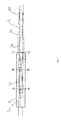
- figure 1 of the drawings illustrates a velocity string safety system in accordance with an embodiment of the present invention.
- the figure illustrates a section of a completion or production tubing 10 including a safety valve nipple 12.
- the nipple 12 will accommodate an appropriate safety valve (not shown).
- the nipple 12 includes a no-go 14 and locking profile 16 positioned above sections of honed bore 18, 19 surrounding a port 20 which communicates with a hydraulic control line 22.
- the operation of the safety valve will be controlled from the surface via the control line 22.
- the figures illustrate the safety valve nipple 12 after the safety valve appropriate for the production tubing 10 has been retrieved and a velocity string 24 and velocity string safety valve 26 run in and installed.
- the figures only illustrate the upper end of the velocity string 24, which includes a nipple engaging portion 28 and above this a portion 30 configured to receive the safety valve 26.
- the nipple engaging portion 28 is perhaps best illustrated in figures 2c and 2d of the drawings and includes a no-go engaging key 32 and a profile engaging key 34.
- the keys may take any appropriate form and may be, for example, dogs, part-circular segments, or split rings.
- Figure 2c illustrates the keys 32, 34 in the running configuration and illustrates the positioning of the keys 32, 34 at the instant the no-go engaging key 32 lands on the safety valve nipple no-go 14.
- the keys 32, 34 form part of an assembly which may move upwards relative to the rest of the velocity string 24 and the keys 32, 34 are also supported by a profiled member 36.
- the inner faces of the keys 32, 34 and the outer face of the profile member 36 are configured such that, on the key 32 engaging the no-go 14, the weight of the velocity string 24 causes the remainder of the velocity string 24, including the profiled member 36, to continue to move downwards relative to the no-go 14.
- the keys 32, 34 travel upwards relative to the profiled member 36 such that the no-go engaging key 32 is retracted while the profile engaging key 34 is extended and retained in the extended position, engaging with the locking profile 14, by the weight of the string 24.
- the velocity string 24 carries two spaced seals 38 which are dimensioned and located to engage with the honed bore sections 18, 19 of the nipple 12.
- the seals 38 in combination with the outer surface of the string 24 and the inner surface of the nipple 12 form an isolated annulus 40 in communication with the safety valve nipple port 20.
- the velocity string 24 is configured to define a fluid passage 42 linking the annulus 40, and thus the port 20 and the control line 22, to a port 44 in the safety valve receiving portion 30 (see figure 2a ).
- FIG. 1 illustrates the safety valve 26 in greater detail.
- the safety valve 26 will generally be run into the well after the velocity string 24 has been secured in the nipple 12.
- the valve 26 includes an arrangement of keys 46 and profiled sprung sleeves 48 which may be manipulated to secure the valve 26 in the upper end of the string 24.
- the valve 26 includes a sprung flapper 50 (see figure 3c ) which is biased to close the valve through bore 52 although the figures illustrate the flapper restrained behind a lockout sleeve 54.
- a spring 56 biases the sleeve 54 towards a retracted position, allowing the flapper 50 to close.
- the sleeve 54 may be retained in the illustrated extended position by hydraulic fluid pressure acting on the upper end of a piston 58 coupled through an appropriate linkage 60 to the upper end of the sleeve 54.
- the piston 58 is moveable in an elongate cylindrical piston chamber 62 which is in fluid communication with a port 64 in the valve body, which port 64 is aligned with the velocity string port 44. Seals 66 are provided on the valve body above and below the port 64 to provide a sealing engagement with the opposing inner diameter of the string 24.
- an operator will be monitoring production from the well and will have identified conditions indicating that provision of a velocity string would be beneficial. For example, in a depleting gas well the velocity of the gas flowing from the reservoir to surface may have decreased to the extent that the gas flow is unable to entrain liquid, leading to a build up of liquid in the well. In this situation the operator will first retrieve the safety valve which would originally be mounted in the safety valve nipple 12. The velocity string 24 is then run into the well. As described above, on the no-go engaging key 32 engaging the nipple no-go 14, the profile engaging key 34 is forced outwards to engage with the locking profile 16, thus securing and supporting the string 24 in the production tubing 10. The safety valve 26 is then run into the upper end of the velocity string 24. The combined assembly is arranged such that the control lines 22 are in communication with the safety valve 26 and the operator thus has full control of the safety valve 26 from surface.
- the system may incorporate an inflow control device (ICD) or valve located in the velocity string below the safety valve nipple 12.
- ICD inflow control device
- the ICD may be coupled to the existing hydraulics such that the ICD may be controlled from the surface and be opened from time to time to, for example, to allow removal of any gas cap that forms in the annulus between the velocity string 24 and the production tubing 10.
Landscapes
- Engineering & Computer Science (AREA)
- Geology (AREA)
- Life Sciences & Earth Sciences (AREA)
- Mining & Mineral Resources (AREA)
- Geochemistry & Mineralogy (AREA)
- Fluid Mechanics (AREA)
- Environmental & Geological Engineering (AREA)
- General Life Sciences & Earth Sciences (AREA)
- Physics & Mathematics (AREA)
- Chemical & Material Sciences (AREA)
- Chemical Kinetics & Catalysis (AREA)
- General Chemical & Material Sciences (AREA)
- Oil, Petroleum & Natural Gas (AREA)
- Pipe Accessories (AREA)
- Earth Drilling (AREA)
- Refuge Islands, Traffic Blockers, Or Guard Fence (AREA)
Applications Claiming Priority (1)
| Application Number | Priority Date | Filing Date | Title |
|---|---|---|---|
| GB1108648.5A GB2491131A (en) | 2011-05-24 | 2011-05-24 | Velocity string installation |
Publications (3)
| Publication Number | Publication Date |
|---|---|
| EP2532830A2 true EP2532830A2 (de) | 2012-12-12 |
| EP2532830A3 EP2532830A3 (de) | 2014-08-27 |
| EP2532830B1 EP2532830B1 (de) | 2018-07-18 |
Family
ID=44279485
Family Applications (1)
| Application Number | Title | Priority Date | Filing Date |
|---|---|---|---|
| EP12169335.2A Active EP2532830B1 (de) | 2011-05-24 | 2012-05-24 | Hochgeschwindigkeitsproduktionsrohrstrang |
Country Status (7)
| Country | Link |
|---|---|
| US (1) | US9228405B2 (de) |
| EP (1) | EP2532830B1 (de) |
| AU (1) | AU2012202988B2 (de) |
| CA (1) | CA2777334C (de) |
| DK (1) | DK2532830T3 (de) |
| GB (1) | GB2491131A (de) |
| RU (1) | RU2539045C2 (de) |
Cited By (1)
| Publication number | Priority date | Publication date | Assignee | Title |
|---|---|---|---|---|
| WO2017218103A1 (en) * | 2016-06-16 | 2017-12-21 | Baker Hughes Incorporated | System and method to install velocity string |
Families Citing this family (3)
| Publication number | Priority date | Publication date | Assignee | Title |
|---|---|---|---|---|
| GB2491131A (en) | 2011-05-24 | 2012-11-28 | Weatherford Lamb | Velocity string installation |
| US9068444B2 (en) * | 2012-02-08 | 2015-06-30 | Weatherford Technology Holdings, Llc | Gas lift system having expandable velocity string |
| NL1044081B1 (en) | 2021-07-02 | 2023-01-10 | Ir Msc Mark Gilbert Sisouw De Zilwa | Method and devices for unloading flow conduits and improving multi-phase flow capacity. |
Family Cites Families (21)
| Publication number | Priority date | Publication date | Assignee | Title |
|---|---|---|---|---|
| US4583591A (en) * | 1983-02-22 | 1986-04-22 | Baker Oil Tools, Inc. | Downhole locking apparatus |
| US4457368A (en) * | 1983-03-25 | 1984-07-03 | Camco, Incorporated | Shearable no go insert for a well lock |
| US4844166A (en) | 1988-06-13 | 1989-07-04 | Camco, Incorporated | Method and apparatus for recompleting wells with coil tubing |
| US4962813A (en) * | 1989-02-28 | 1990-10-16 | Otis Engineering Corporation | Well tool locking system for staggered bore |
| US4997038A (en) * | 1989-02-28 | 1991-03-05 | Otis Engineering Corporation | Lock mandrel latch assembly |
| US5027903A (en) * | 1990-07-17 | 1991-07-02 | Gipson Thomas C | Coiled tubing velocity string hangoff method and apparatus |
| US5398764A (en) * | 1993-07-12 | 1995-03-21 | Halliburton Company | Well tool system and method for use in a well conduit |
| GB9612609D0 (en) * | 1996-06-17 | 1996-08-21 | Petroline Wireline Services | Downhole apparatus |
| US6523613B2 (en) * | 2000-10-20 | 2003-02-25 | Schlumberger Technology Corp. | Hydraulically actuated valve |
| US7066284B2 (en) | 2001-11-14 | 2006-06-27 | Halliburton Energy Services, Inc. | Method and apparatus for a monodiameter wellbore, monodiameter casing, monobore, and/or monowell |
| US7051805B2 (en) * | 2001-12-20 | 2006-05-30 | Baker Hughes Incorporated | Expandable packer with anchoring feature |
| US7188674B2 (en) | 2002-09-05 | 2007-03-13 | Weatherford/Lamb, Inc. | Downhole milling machine and method of use |
| RU2242579C2 (ru) * | 2002-11-20 | 2004-12-20 | Общество с ограниченной ответственностью "Кубаньгазпром" | Способ эксплуатации насосно-компрессорных труб в скважине |
| WO2005103440A2 (en) * | 2004-04-27 | 2005-11-03 | Schlumberger Canada Limited | Deploying an assembly into a well |
| RU2284406C2 (ru) * | 2005-01-11 | 2006-09-27 | Сергей Александрович Мороз | Пакер |
| DK1888873T3 (da) | 2005-06-08 | 2014-01-27 | Baker Hughes Inc | Fremgangsmåde og apparatur til kontinuerlig injektion af fluid i et borehul under opretholdelse af sikkerhedsventilfunktion |
| US8251147B2 (en) * | 2005-06-08 | 2012-08-28 | Baker Hughes Incorporated | Method and apparatus for continuously injecting fluid in a wellbore while maintaining safety valve operation |
| US7984760B2 (en) * | 2006-04-03 | 2011-07-26 | Exxonmobil Upstream Research Company | Wellbore method and apparatus for sand and inflow control during well operations |
| RU65562U1 (ru) * | 2007-03-28 | 2007-08-10 | Открытое акционерное общество "Татнефть" им. В.Д. Шашина | Пакерующее устройство для избирательного испытания пластов |
| US7980315B2 (en) * | 2008-03-17 | 2011-07-19 | Baker Hughes Incorporated | System and method for selectively communicatable hydraulic nipples |
| GB2491131A (en) | 2011-05-24 | 2012-11-28 | Weatherford Lamb | Velocity string installation |
-
2011
- 2011-05-24 GB GB1108648.5A patent/GB2491131A/en not_active Withdrawn
-
2012
- 2012-05-22 AU AU2012202988A patent/AU2012202988B2/en not_active Ceased
- 2012-05-23 US US13/478,894 patent/US9228405B2/en active Active
- 2012-05-23 CA CA2777334A patent/CA2777334C/en not_active Expired - Fee Related
- 2012-05-23 RU RU2012121352/03A patent/RU2539045C2/ru not_active IP Right Cessation
- 2012-05-24 DK DK12169335.2T patent/DK2532830T3/en active
- 2012-05-24 EP EP12169335.2A patent/EP2532830B1/de active Active
Non-Patent Citations (1)
| Title |
|---|
| None |
Cited By (4)
| Publication number | Priority date | Publication date | Assignee | Title |
|---|---|---|---|---|
| WO2017218103A1 (en) * | 2016-06-16 | 2017-12-21 | Baker Hughes Incorporated | System and method to install velocity string |
| GB2566417A (en) * | 2016-06-16 | 2019-03-13 | Baker Hughes A Ge Co Llc | System and method to install velocity string |
| US10337269B2 (en) | 2016-06-16 | 2019-07-02 | Baker Hughes, A Ge Company, Llc | System and method to install velocity string |
| GB2566417B (en) * | 2016-06-16 | 2021-07-28 | Baker Hughes A Ge Co Llc | System and method to install velocity string |
Also Published As
| Publication number | Publication date |
|---|---|
| GB201108648D0 (en) | 2011-07-06 |
| US9228405B2 (en) | 2016-01-05 |
| GB2491131A (en) | 2012-11-28 |
| AU2012202988B2 (en) | 2015-03-05 |
| CA2777334C (en) | 2016-05-03 |
| RU2012121352A (ru) | 2013-11-27 |
| AU2012202988A1 (en) | 2012-12-13 |
| CA2777334A1 (en) | 2012-11-24 |
| EP2532830A3 (de) | 2014-08-27 |
| DK2532830T3 (en) | 2018-11-12 |
| US20120298377A1 (en) | 2012-11-29 |
| EP2532830B1 (de) | 2018-07-18 |
| RU2539045C2 (ru) | 2015-01-10 |
Similar Documents
| Publication | Publication Date | Title |
|---|---|---|
| CA2383683C (en) | Well completion method and apparatus | |
| CA2660219C (en) | System and method for thru tubing deepening of gas lift | |
| CA2445870C (en) | Automatic tubing filler | |
| US9638002B2 (en) | Activated reverse-out valve | |
| CA2850974C (en) | Downhole tool with pumpable section | |
| US9638001B2 (en) | Method for producing hydrocarbon gas from a wellbore and valve assembly | |
| US8668018B2 (en) | Selective dart system for actuating downhole tools and methods of using same | |
| CA2870514A1 (en) | Completing long, deviated wells | |
| US9181779B2 (en) | Activated reverse-out valve | |
| CN106661927A (zh) | 接合输送的完井工具和操作 | |
| CA2777334C (en) | Velocity strings | |
| CA2884157A1 (en) | Christmas tree and method | |
| EP2964873B1 (de) | Drahtgebundener gewickelter rohrstrang und verfahren zum betrieb solch eines gewickelten rohrstrangs | |
| EP3087246B1 (de) | Verfahren zum durchführen einer leitung in bohrlöchern mit grösserer reichweite | |
| CA2886440C (en) | Method and apparatus for installing a liner and bridge plug | |
| US12234708B2 (en) | Closing inflow control device using dissolvable balls and plugs | |
| EP2592218A1 (de) | Ventilanordnung für ein Kohlenwasserstoffbohrloch, Verfahren zum nachträglichen Einbau einer Ventilanordnung und Unteroberflächenverwendung solch einer Ventilanordnung |
Legal Events
| Date | Code | Title | Description |
|---|---|---|---|
| PUAI | Public reference made under article 153(3) epc to a published international application that has entered the european phase |
Free format text: ORIGINAL CODE: 0009012 |
|
| 17P | Request for examination filed |
Effective date: 20120524 |
|
| AK | Designated contracting states |
Kind code of ref document: A2 Designated state(s): AL AT BE BG CH CY CZ DE DK EE ES FI FR GB GR HR HU IE IS IT LI LT LU LV MC MK MT NL NO PL PT RO RS SE SI SK SM TR |
|
| AX | Request for extension of the european patent |
Extension state: BA ME |
|
| PUAL | Search report despatched |
Free format text: ORIGINAL CODE: 0009013 |
|
| AK | Designated contracting states |
Kind code of ref document: A3 Designated state(s): AL AT BE BG CH CY CZ DE DK EE ES FI FR GB GR HR HU IE IS IT LI LT LU LV MC MK MT NL NO PL PT RO RS SE SI SK SM TR |
|
| AX | Request for extension of the european patent |
Extension state: BA ME |
|
| RIC1 | Information provided on ipc code assigned before grant |
Ipc: E21B 23/02 20060101AFI20140722BHEP Ipc: E21B 34/10 20060101ALI20140722BHEP Ipc: E21B 33/04 20060101ALI20140722BHEP |
|
| RAP1 | Party data changed (applicant data changed or rights of an application transferred) |
Owner name: WEATHERFORD/LAMB, INC. |
|
| RAP1 | Party data changed (applicant data changed or rights of an application transferred) |
Owner name: WEATHERFORD TECHNOLOGY HOLDINGS, LLC |
|
| 17Q | First examination report despatched |
Effective date: 20160720 |
|
| STAA | Information on the status of an ep patent application or granted ep patent |
Free format text: STATUS: EXAMINATION IS IN PROGRESS |
|
| GRAP | Despatch of communication of intention to grant a patent |
Free format text: ORIGINAL CODE: EPIDOSNIGR1 |
|
| STAA | Information on the status of an ep patent application or granted ep patent |
Free format text: STATUS: GRANT OF PATENT IS INTENDED |
|
| INTG | Intention to grant announced |
Effective date: 20180103 |
|
| GRAJ | Information related to disapproval of communication of intention to grant by the applicant or resumption of examination proceedings by the epo deleted |
Free format text: ORIGINAL CODE: EPIDOSDIGR1 |
|
| STAA | Information on the status of an ep patent application or granted ep patent |
Free format text: STATUS: EXAMINATION IS IN PROGRESS |
|
| GRAR | Information related to intention to grant a patent recorded |
Free format text: ORIGINAL CODE: EPIDOSNIGR71 |
|
| GRAS | Grant fee paid |
Free format text: ORIGINAL CODE: EPIDOSNIGR3 |
|
| STAA | Information on the status of an ep patent application or granted ep patent |
Free format text: STATUS: GRANT OF PATENT IS INTENDED |
|
| GRAA | (expected) grant |
Free format text: ORIGINAL CODE: 0009210 |
|
| STAA | Information on the status of an ep patent application or granted ep patent |
Free format text: STATUS: THE PATENT HAS BEEN GRANTED |
|
| INTC | Intention to grant announced (deleted) | ||
| INTG | Intention to grant announced |
Effective date: 20180606 |
|
| AK | Designated contracting states |
Kind code of ref document: B1 Designated state(s): AL AT BE BG CH CY CZ DE DK EE ES FI FR GB GR HR HU IE IS IT LI LT LU LV MC MK MT NL NO PL PT RO RS SE SI SK SM TR |
|
| REG | Reference to a national code |
Ref country code: GB Ref legal event code: FG4D |
|
| REG | Reference to a national code |
Ref country code: CH Ref legal event code: EP |
|
| REG | Reference to a national code |
Ref country code: IE Ref legal event code: FG4D |
|
| REG | Reference to a national code |
Ref country code: AT Ref legal event code: REF Ref document number: 1019562 Country of ref document: AT Kind code of ref document: T Effective date: 20180815 |
|
| REG | Reference to a national code |
Ref country code: DE Ref legal event code: R096 Ref document number: 602012048538 Country of ref document: DE |
|
| REG | Reference to a national code |
Ref country code: NL Ref legal event code: FP |
|
| REG | Reference to a national code |
Ref country code: DK Ref legal event code: T3 Effective date: 20181106 |
|
| REG | Reference to a national code |
Ref country code: NO Ref legal event code: T2 Effective date: 20180718 |
|
| REG | Reference to a national code |
Ref country code: LT Ref legal event code: MG4D |
|
| REG | Reference to a national code |
Ref country code: AT Ref legal event code: MK05 Ref document number: 1019562 Country of ref document: AT Kind code of ref document: T Effective date: 20180718 |
|
| PG25 | Lapsed in a contracting state [announced via postgrant information from national office to epo] |
Ref country code: AT Free format text: LAPSE BECAUSE OF FAILURE TO SUBMIT A TRANSLATION OF THE DESCRIPTION OR TO PAY THE FEE WITHIN THE PRESCRIBED TIME-LIMIT Effective date: 20180718 Ref country code: RS Free format text: LAPSE BECAUSE OF FAILURE TO SUBMIT A TRANSLATION OF THE DESCRIPTION OR TO PAY THE FEE WITHIN THE PRESCRIBED TIME-LIMIT Effective date: 20180718 Ref country code: BG Free format text: LAPSE BECAUSE OF FAILURE TO SUBMIT A TRANSLATION OF THE DESCRIPTION OR TO PAY THE FEE WITHIN THE PRESCRIBED TIME-LIMIT Effective date: 20181018 Ref country code: SE Free format text: LAPSE BECAUSE OF FAILURE TO SUBMIT A TRANSLATION OF THE DESCRIPTION OR TO PAY THE FEE WITHIN THE PRESCRIBED TIME-LIMIT Effective date: 20180718 Ref country code: FI Free format text: LAPSE BECAUSE OF FAILURE TO SUBMIT A TRANSLATION OF THE DESCRIPTION OR TO PAY THE FEE WITHIN THE PRESCRIBED TIME-LIMIT Effective date: 20180718 Ref country code: GR Free format text: LAPSE BECAUSE OF FAILURE TO SUBMIT A TRANSLATION OF THE DESCRIPTION OR TO PAY THE FEE WITHIN THE PRESCRIBED TIME-LIMIT Effective date: 20181019 Ref country code: IS Free format text: LAPSE BECAUSE OF FAILURE TO SUBMIT A TRANSLATION OF THE DESCRIPTION OR TO PAY THE FEE WITHIN THE PRESCRIBED TIME-LIMIT Effective date: 20181118 Ref country code: LT Free format text: LAPSE BECAUSE OF FAILURE TO SUBMIT A TRANSLATION OF THE DESCRIPTION OR TO PAY THE FEE WITHIN THE PRESCRIBED TIME-LIMIT Effective date: 20180718 Ref country code: PL Free format text: LAPSE BECAUSE OF FAILURE TO SUBMIT A TRANSLATION OF THE DESCRIPTION OR TO PAY THE FEE WITHIN THE PRESCRIBED TIME-LIMIT Effective date: 20180718 |
|
| PG25 | Lapsed in a contracting state [announced via postgrant information from national office to epo] |
Ref country code: LV Free format text: LAPSE BECAUSE OF FAILURE TO SUBMIT A TRANSLATION OF THE DESCRIPTION OR TO PAY THE FEE WITHIN THE PRESCRIBED TIME-LIMIT Effective date: 20180718 Ref country code: HR Free format text: LAPSE BECAUSE OF FAILURE TO SUBMIT A TRANSLATION OF THE DESCRIPTION OR TO PAY THE FEE WITHIN THE PRESCRIBED TIME-LIMIT Effective date: 20180718 Ref country code: AL Free format text: LAPSE BECAUSE OF FAILURE TO SUBMIT A TRANSLATION OF THE DESCRIPTION OR TO PAY THE FEE WITHIN THE PRESCRIBED TIME-LIMIT Effective date: 20180718 |
|
| REG | Reference to a national code |
Ref country code: DE Ref legal event code: R097 Ref document number: 602012048538 Country of ref document: DE |
|
| PG25 | Lapsed in a contracting state [announced via postgrant information from national office to epo] |
Ref country code: RO Free format text: LAPSE BECAUSE OF FAILURE TO SUBMIT A TRANSLATION OF THE DESCRIPTION OR TO PAY THE FEE WITHIN THE PRESCRIBED TIME-LIMIT Effective date: 20180718 Ref country code: CZ Free format text: LAPSE BECAUSE OF FAILURE TO SUBMIT A TRANSLATION OF THE DESCRIPTION OR TO PAY THE FEE WITHIN THE PRESCRIBED TIME-LIMIT Effective date: 20180718 Ref country code: ES Free format text: LAPSE BECAUSE OF FAILURE TO SUBMIT A TRANSLATION OF THE DESCRIPTION OR TO PAY THE FEE WITHIN THE PRESCRIBED TIME-LIMIT Effective date: 20180718 Ref country code: EE Free format text: LAPSE BECAUSE OF FAILURE TO SUBMIT A TRANSLATION OF THE DESCRIPTION OR TO PAY THE FEE WITHIN THE PRESCRIBED TIME-LIMIT Effective date: 20180718 |
|
| PLBE | No opposition filed within time limit |
Free format text: ORIGINAL CODE: 0009261 |
|
| STAA | Information on the status of an ep patent application or granted ep patent |
Free format text: STATUS: NO OPPOSITION FILED WITHIN TIME LIMIT |
|
| PG25 | Lapsed in a contracting state [announced via postgrant information from national office to epo] |
Ref country code: SM Free format text: LAPSE BECAUSE OF FAILURE TO SUBMIT A TRANSLATION OF THE DESCRIPTION OR TO PAY THE FEE WITHIN THE PRESCRIBED TIME-LIMIT Effective date: 20180718 Ref country code: SK Free format text: LAPSE BECAUSE OF FAILURE TO SUBMIT A TRANSLATION OF THE DESCRIPTION OR TO PAY THE FEE WITHIN THE PRESCRIBED TIME-LIMIT Effective date: 20180718 |
|
| 26N | No opposition filed |
Effective date: 20190423 |
|
| PG25 | Lapsed in a contracting state [announced via postgrant information from national office to epo] |
Ref country code: SI Free format text: LAPSE BECAUSE OF FAILURE TO SUBMIT A TRANSLATION OF THE DESCRIPTION OR TO PAY THE FEE WITHIN THE PRESCRIBED TIME-LIMIT Effective date: 20180718 |
|
| REG | Reference to a national code |
Ref country code: CH Ref legal event code: PL |
|
| PG25 | Lapsed in a contracting state [announced via postgrant information from national office to epo] |
Ref country code: LI Free format text: LAPSE BECAUSE OF NON-PAYMENT OF DUE FEES Effective date: 20190531 Ref country code: CH Free format text: LAPSE BECAUSE OF NON-PAYMENT OF DUE FEES Effective date: 20190531 Ref country code: MC Free format text: LAPSE BECAUSE OF FAILURE TO SUBMIT A TRANSLATION OF THE DESCRIPTION OR TO PAY THE FEE WITHIN THE PRESCRIBED TIME-LIMIT Effective date: 20180718 |
|
| REG | Reference to a national code |
Ref country code: BE Ref legal event code: MM Effective date: 20190531 |
|
| PG25 | Lapsed in a contracting state [announced via postgrant information from national office to epo] |
Ref country code: LU Free format text: LAPSE BECAUSE OF NON-PAYMENT OF DUE FEES Effective date: 20190524 |
|
| PG25 | Lapsed in a contracting state [announced via postgrant information from national office to epo] |
Ref country code: TR Free format text: LAPSE BECAUSE OF FAILURE TO SUBMIT A TRANSLATION OF THE DESCRIPTION OR TO PAY THE FEE WITHIN THE PRESCRIBED TIME-LIMIT Effective date: 20180718 |
|
| PG25 | Lapsed in a contracting state [announced via postgrant information from national office to epo] |
Ref country code: IE Free format text: LAPSE BECAUSE OF NON-PAYMENT OF DUE FEES Effective date: 20190524 Ref country code: IT Free format text: LAPSE BECAUSE OF NON-PAYMENT OF DUE FEES Effective date: 20190524 |
|
| PG25 | Lapsed in a contracting state [announced via postgrant information from national office to epo] |
Ref country code: BE Free format text: LAPSE BECAUSE OF NON-PAYMENT OF DUE FEES Effective date: 20190531 |
|
| PG25 | Lapsed in a contracting state [announced via postgrant information from national office to epo] |
Ref country code: PT Free format text: LAPSE BECAUSE OF FAILURE TO SUBMIT A TRANSLATION OF THE DESCRIPTION OR TO PAY THE FEE WITHIN THE PRESCRIBED TIME-LIMIT Effective date: 20181118 Ref country code: FR Free format text: LAPSE BECAUSE OF NON-PAYMENT OF DUE FEES Effective date: 20190531 |
|
| REG | Reference to a national code |
Ref country code: NL Ref legal event code: RC Free format text: DETAILS LICENCE OR PLEDGE: RIGHT OF PLEDGE, ESTABLISHED Name of requester: DEUTSCHE BANK TRUST COMPANY AMERICAS Effective date: 20200723 |
|
| REG | Reference to a national code |
Ref country code: GB Ref legal event code: 732E Free format text: REGISTERED BETWEEN 20200813 AND 20200819 |
|
| REG | Reference to a national code |
Ref country code: GB Ref legal event code: 732E Free format text: REGISTERED BETWEEN 20201126 AND 20201202 |
|
| REG | Reference to a national code |
Ref country code: GB Ref legal event code: 732E Free format text: REGISTERED BETWEEN 20210225 AND 20210303 |
|
| PG25 | Lapsed in a contracting state [announced via postgrant information from national office to epo] |
Ref country code: CY Free format text: LAPSE BECAUSE OF FAILURE TO SUBMIT A TRANSLATION OF THE DESCRIPTION OR TO PAY THE FEE WITHIN THE PRESCRIBED TIME-LIMIT Effective date: 20180718 |
|
| PG25 | Lapsed in a contracting state [announced via postgrant information from national office to epo] |
Ref country code: HU Free format text: LAPSE BECAUSE OF FAILURE TO SUBMIT A TRANSLATION OF THE DESCRIPTION OR TO PAY THE FEE WITHIN THE PRESCRIBED TIME-LIMIT; INVALID AB INITIO Effective date: 20120524 Ref country code: MT Free format text: LAPSE BECAUSE OF FAILURE TO SUBMIT A TRANSLATION OF THE DESCRIPTION OR TO PAY THE FEE WITHIN THE PRESCRIBED TIME-LIMIT Effective date: 20180718 |
|
| PGFP | Annual fee paid to national office [announced via postgrant information from national office to epo] |
Ref country code: DE Payment date: 20210427 Year of fee payment: 10 |
|
| PG25 | Lapsed in a contracting state [announced via postgrant information from national office to epo] |
Ref country code: MK Free format text: LAPSE BECAUSE OF FAILURE TO SUBMIT A TRANSLATION OF THE DESCRIPTION OR TO PAY THE FEE WITHIN THE PRESCRIBED TIME-LIMIT Effective date: 20180718 |
|
| REG | Reference to a national code |
Ref country code: DE Ref legal event code: R119 Ref document number: 602012048538 Country of ref document: DE |
|
| PG25 | Lapsed in a contracting state [announced via postgrant information from national office to epo] |
Ref country code: DE Free format text: LAPSE BECAUSE OF NON-PAYMENT OF DUE FEES Effective date: 20221201 |
|
| P01 | Opt-out of the competence of the unified patent court (upc) registered |
Effective date: 20230922 |
|
| PGFP | Annual fee paid to national office [announced via postgrant information from national office to epo] |
Ref country code: NL Payment date: 20250409 Year of fee payment: 14 |
|
| PGFP | Annual fee paid to national office [announced via postgrant information from national office to epo] |
Ref country code: DK Payment date: 20250516 Year of fee payment: 14 |
|
| PGFP | Annual fee paid to national office [announced via postgrant information from national office to epo] |
Ref country code: NO Payment date: 20250509 Year of fee payment: 14 |
|
| PGFP | Annual fee paid to national office [announced via postgrant information from national office to epo] |
Ref country code: GB Payment date: 20260310 Year of fee payment: 15 |