EP2532832A2 - Haftmittel mit röhrenförmigem Steinanker - Google Patents
Haftmittel mit röhrenförmigem Steinanker Download PDFInfo
- Publication number
- EP2532832A2 EP2532832A2 EP12171061A EP12171061A EP2532832A2 EP 2532832 A2 EP2532832 A2 EP 2532832A2 EP 12171061 A EP12171061 A EP 12171061A EP 12171061 A EP12171061 A EP 12171061A EP 2532832 A2 EP2532832 A2 EP 2532832A2
- Authority
- EP
- European Patent Office
- Prior art keywords
- housing
- compartment
- adhesive
- cartridge according
- cartridge
- Prior art date
- Legal status (The legal status is an assumption and is not a legal conclusion. Google has not performed a legal analysis and makes no representation as to the accuracy of the status listed.)
- Withdrawn
Links
- 239000000853 adhesive Substances 0.000 title claims abstract description 103
- 230000001070 adhesive effect Effects 0.000 title claims abstract description 103
- 239000011435 rock Substances 0.000 title claims abstract description 82
- 239000012530 fluid Substances 0.000 claims abstract description 59
- 238000003825 pressing Methods 0.000 claims description 36
- 239000000463 material Substances 0.000 claims description 18
- 229920002457 flexible plastic Polymers 0.000 claims description 7
- 238000000638 solvent extraction Methods 0.000 claims description 6
- 229920003023 plastic Polymers 0.000 claims description 5
- 239000004033 plastic Substances 0.000 claims description 5
- 230000003068 static effect Effects 0.000 description 23
- 239000011347 resin Substances 0.000 description 18
- 229920005989 resin Polymers 0.000 description 18
- 230000015572 biosynthetic process Effects 0.000 description 16
- 238000005755 formation reaction Methods 0.000 description 16
- 238000007789 sealing Methods 0.000 description 13
- 238000004891 communication Methods 0.000 description 8
- 239000000203 mixture Substances 0.000 description 7
- XLYOFNOQVPJJNP-UHFFFAOYSA-N water Substances O XLYOFNOQVPJJNP-UHFFFAOYSA-N 0.000 description 6
- 239000002775 capsule Substances 0.000 description 5
- 230000000295 complement effect Effects 0.000 description 3
- 230000008878 coupling Effects 0.000 description 3
- 238000010168 coupling process Methods 0.000 description 3
- 238000005859 coupling reaction Methods 0.000 description 3
- 239000007788 liquid Substances 0.000 description 3
- 230000007246 mechanism Effects 0.000 description 3
- 230000004913 activation Effects 0.000 description 2
- 230000003466 anti-cipated effect Effects 0.000 description 2
- 230000002706 hydrostatic effect Effects 0.000 description 2
- 239000007769 metal material Substances 0.000 description 2
- 238000000034 method Methods 0.000 description 2
- 230000008569 process Effects 0.000 description 2
- 239000007787 solid Substances 0.000 description 2
- 230000000007 visual effect Effects 0.000 description 2
- 102000004190 Enzymes Human genes 0.000 description 1
- 108090000790 Enzymes Proteins 0.000 description 1
- 229910001209 Low-carbon steel Inorganic materials 0.000 description 1
- 239000004823 Reactive adhesive Substances 0.000 description 1
- 230000009471 action Effects 0.000 description 1
- 239000012190 activator Substances 0.000 description 1
- 238000004026 adhesive bonding Methods 0.000 description 1
- XAGFODPZIPBFFR-UHFFFAOYSA-N aluminium Chemical compound [Al] XAGFODPZIPBFFR-UHFFFAOYSA-N 0.000 description 1
- 229910052782 aluminium Inorganic materials 0.000 description 1
- 239000004411 aluminium Substances 0.000 description 1
- 230000004888 barrier function Effects 0.000 description 1
- 230000008901 benefit Effects 0.000 description 1
- 230000003197 catalytic effect Effects 0.000 description 1
- 238000006243 chemical reaction Methods 0.000 description 1
- 238000010276 construction Methods 0.000 description 1
- 239000011440 grout Substances 0.000 description 1
- 238000009434 installation Methods 0.000 description 1
- 239000012528 membrane Substances 0.000 description 1
- 238000004806 packaging method and process Methods 0.000 description 1
- 238000012856 packing Methods 0.000 description 1
- 230000002250 progressing effect Effects 0.000 description 1
- 238000007363 ring formation reaction Methods 0.000 description 1
- 230000003319 supportive effect Effects 0.000 description 1
Images


Classifications
-
- E—FIXED CONSTRUCTIONS
- E21—EARTH OR ROCK DRILLING; MINING
- E21D—SHAFTS; TUNNELS; GALLERIES; LARGE UNDERGROUND CHAMBERS
- E21D20/00—Setting anchoring-bolts
- E21D20/02—Setting anchoring-bolts with provisions for grouting
- E21D20/025—Grouting with organic components, e.g. resin
- E21D20/026—Cartridges; Grouting charges
-
- E—FIXED CONSTRUCTIONS
- E21—EARTH OR ROCK DRILLING; MINING
- E21D—SHAFTS; TUNNELS; GALLERIES; LARGE UNDERGROUND CHAMBERS
- E21D20/00—Setting anchoring-bolts
- E21D20/02—Setting anchoring-bolts with provisions for grouting
- E21D20/025—Grouting with organic components, e.g. resin
Definitions
- This invention relates to a rock anchor for use in full column adhesive bonding applications.
- a problem with using a resin or grout to secure a rock anchor within a rock hole is that the resin, typically comprising of an adhesive resinous component and a catalytic component, needs to be adequately mixed for the resultant resin mixture to set with sufficient binding strength.
- rock anchor and rock bolt are used interchangeably to describe a device which has an elongate body, and which is inserted into a hole drilled into a rock face, to stabilize the rock to prevent collapse or rock fall.
- the resin is an expensive consumable that is often wasted; introduced into the rock hole in cartridges in amounts surplus to requirement for the particular hole-size, resulting in resin leaking from the hole.
- Resin cartridges are also often damaged during storage or transportation to site because of the delicate frangible nature of the cartridge membrane.
- adheresive refers to a system which includes at least one low viscosity liquid adhesive component which is free-flowing before activation and which after activation, sets or hardens.
- An “adhesive component” bears a corresponding meaning.
- Fluid pressure as hereinafter used includes pressure that is caused hydrostatically or hydraulically.
- the invention provides a cartridge for containing a multi-component adhesive system for use in a rock anchor installation which includes a rigid tubular housing, which has a forward end and an opposed trailing end, within which at least one compartment is defined in which is contained an adhesive component wherein the at least one compartment yields to volumetrically reduce, under fluid pressure created by a fluid input into the housing, thereby to extrude the adhesive component.
- the fluid is input from the trailing end and the adhesive component is extruded from the forward end.
- the housing may be complementarily dimensioned to fit within the tubular body of a tubular rock anchor.
- the rigid tubular housing is made from a rigid plastics material.
- the cartridge may contain a pressing member located within the housing, between the at least one compartment and the trailing end, which moves under pressure created by a fluid input into the housing, to cause the at least one compartment to extrude its adhesive component.
- the pressing member may be slidingly, preferably sealingly, engaged with inner walls of the housing.
- a first compartment and a second compartment are defined, in which are respectively contained a first adhesive component and a second adhesive component.
- Each compartment may be a discrete compartment, spaced from each other and sidewalls of the cartridge housing.
- at least one wall of each compartment may be integrally formed with, or attached to, sidewalls of the cartridge body.
- the housing may include at least one axially extending internal partitioning wall which divides the housing's interior into the first compartment and the second compartment.
- the cartridge may include an elongate tube which fits within the housing in co-axial extension and which defines the first compartment and whereby the second compartment is defined by a space between the housing and the tube.
- the tube may have walls which are adapted to axially compress in a controlled manner about predefined annular zones, when a force is applied at one end, to extrude its adhesive content.
- the tube is made of a suitable flexible plastics material.
- the tube may be a tubular bellows-type tube, the walls of which comprise a plurality of corrugated annular sections, each one of these sections defining an annular zone about which the tube is adapted to axially compress.
- the cartridge may be closed at the forward end, through which a sealed outlet from each of the compartments is defined.
- An indicator material which changes colour to provide a visual indication of the extent to which the adhesive components have set when mixed, may be included with a component of the adhesive system.
- the invention also extends to an adhesive containing container for use with a tubular rock anchor which has a tubular bellows-type body, the walls of which comprise a plurality of corrugated annular sections, each one of these sections defining an annular zone about which the container is adapted to axially compress.
- the body may have an outlet end and an opposed end, which is closed.
- the container is made of a suitable flexible plastics material.
- the invention further provides a rock anchor which includes an elongate tubular body which extends between a first end and an opposing second end, a cartridge for containing a multi-component adhesive system, in the tubular body, wherein the cartridge has a rigid tubular housing within which at least one compartment is defined, in which is contained an adhesive component of the system, wherein the at least one compartment yields to volumetrically reduce under fluid pressure created by a fluid input into the housing, thereby to extrude the adhesive components.
- the anchor includes a fluid inlet valve assembly which introduces the fluid from the first end and wherein the at least one adhesive component is extruded towards the second end.
- the inlet valve assembly may be sealingly engaged with a trailing end of the cartridge housing to avoid flow of the fluid into the space between the anchor body and the cartridge housing.
- the cartridge contains a pressing member located within the housing, between the at least one compartment and the trailing end, which moves under pressure created by the fluid input, towards the second end of the anchor body, thereby to volumetrically reduce the at least one compartment.
- the pressing member may be slidingly, preferably sealingly, engaged with inner walls of the housing.
- the cartridge may include an elongate tube which fits within the housing in co-axial extension and which defines the at least one compartment.
- a first compartment and a second compartment are defined, in which are respectively contained a first adhesive and a second adhesive component.
- the second compartment maybe defined by a space between the housing and the tube.
- the tube may have walls which are adapted to axially compress in a controlled manner about predefined annular zones, when a force is applied at one end, to extrude its adhesive content.
- the tube is made of a suitable flexible plastics material.
- the tube may be a tubular bellows-type tube, the walls of which comprise a plurality of corrugated annular sections, each one of these sections defining an annular zone about which the tube is adapted to axially compress.
- the cartridge may be closed at the forward end, through which a sealed outlet from each of the compartments is defined.
- the rock anchor may include a mixing means into which each adhesive component of the adhesive passes to be reactively mixed.
- the mixing means may be connected to the second end or at least partially located within the body adjacent the second end.
- the mixing means may be a static mixer.
- the invention further provides a rock anchor which includes an elongate tubular body which extends between a first end and an opposing second end, an adhesive containing container as described above, a pressing member located within the tubular body between the container and the first end, and a fluid inlet valve assembly, at or near the first end, wherein a fluid introduced into the tubular body causes the member to advance under pressure, through the valve assembly, towards the second end thereby to compress the container and to cause the adhesive content of the container to extrude therefrom.
- a rock anchor which includes an elongate tubular body which extends between a first end and an opposing second end, an adhesive containing container as described above, a pressing member located within the tubular body between the container and the first end, and a fluid inlet valve assembly, at or near the first end, wherein a fluid introduced into the tubular body causes the member to advance under pressure, through the valve assembly, towards the second end thereby to compress the container and to cause the adhesive content of the container to extrude therefrom.
- the pressing member may slidingly, preferably sealingly, engage the inner walls of the tubular body.
- the adhesive containing container may include a tubular bellows-type body, the walls of which comprise a plurality of corrugated annular sections, each one of these sections defining the annular zone about which the container is adapted to axially compress.
- tubular body's second end lies adjacent a blind end of a rock hole.
- the tubular body is cylindrical and made from a metallic material.
- the extruded adhesive contents of the cartridge may then flow into an annular space defined between an outer wall of the anchor body and the wall of a rock hole, into which the anchor is placed, to set and secure the anchor in place in the hole.
- the tubular body has a predetermined volume to contain a cartridge with an amount of adhesive which is sufficient to substantially fill the annular space along a full length of the rock hole.
- the rock anchor may include a mixing means, into which each adhesive component of the adhesive passes to be reactively mixed.
- the mixing means may be connected to the second end or at least partially located within the body adjacent the second end.
- the mixing means may be a static mixer.
- the invention provides an adhesive containing container for use with a tubular rock anchor which has a tubular bellows-type body, the walls of which include a plurality of corrugated annular sections, each of which axially compress when a force is applied at one end of the body.
- the adhesive containing container may be made of a flexible plastics material.
- the invention provides a rock anchor which includes an elongate tubular body which extends between a first end and an opposing second end, a cartridge for containing a multi component adhesive which has a rigid tubular housing within which at least one compartment is defined, in which is contained an adhesive component of the system, in the tubular body, wherein the at least one compartment yields to volumetrically reduce, under fluid pressure created by a fluid input into the housing, thereby to extrude the adhesive component.
- the cartridge may include a pressing member contained within the housing, between the compartment and a fluid input end, which moves under pressure created by the fluid input, towards an opposed output end of the housing.
- the pressing member may be sealingly engaged with the housing.
- the rock anchor may include a fluid inlet valve assembly which introduces the fluid input from the first end thereby to extrude the at least one adhesive component towards the second end.
- the inlet valve assembly may be sealingly engaged with an input end of the cartridge housing.
- the cartridge may includes a tube which fits within the housing in co-axial extension to define the at least one compartment.
- the walls of the tube may be adapted to axially compress in a controlled manner about predefined annular zones.
- the tube may have a tubular bellows-type body which includes a plurality of corrugated annular sections about which the tube axially compresses when a force is applied at one end of the body.
- the tube may be made of a flexible plastics material.
- a first compartment, containing a first adhesive component, and a second compartment containing a second adhesive component, may be defined within the housing.
- the rock anchor may include a mixing means, into which each adhesive component of the adhesive system is extruded to be mixed.
- the mixing means may be a static mixer.
- the invention provides a rock anchor which includes an elongate tubular body which extends between a first end and an opposing second end, an adhesive containing container, as described above, containing a first adhesive component of an adhesive system, a pressing member located within the tubular body between the container and the first end and a fluid inlet valve assembly attached, at or near the first end, wherein a fluid introduced into the tubular body through the valve assembly, causes the member to advance, under pressure, towards the second end thereby to compress the container to cause the adhesive component to extrude therefrom.
- the pressing member may be sealingly engaged with the inner walls of the tubular body.
- the tubular body may be cylindrical and made from a metallic material.
- a second adhesive component may be contained within a space between the container and the anchor body.
- the rock anchor may include a mixing means, into which each adhesive component of the adhesive passes to be reactively mixed.
- a modular rock anchor which includes a mixing means, an adhesive containing cartridge and an inlet valve assembly, each respectively serially connected and in fluid communication with the other to provide a modular assembly, and a rigid tubular sheath which at least partially encloses the modular assembly.
- the mixing means may be a static mixer.
- the cartridge may be any cartridge as described above.
- the tubular sheath may be a metallic tube or cylinder.
- a rock anchor which extends between a first end and an opposing second end, an adhesive containing container, containing an adhesive component, within the tubular body, which yields to volumetrically reduce under fluid pressure created by a fluid input into the housing, thereby to extrude the adhesive component.
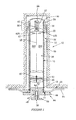
- a rock anchor 10 which includes an elongate tubular body 12 which is made from a suitable material, for example a mild steel and which extends between a first end 14 and a partially closed second end 16.
- the tubular body contains a cartridge 18 which includes a cylindrical housing 19 made of a rigid plastics material, which is of complementary dimension to fit within the body.
- the cartridge housing has a leading end 20 and an opposed trailing end 24.
- the cartridge 18 includes a first compartment and a second compartment, respectively designated 26A and 26B, divided by a partitioning wall 28, each of which contains a discrete fluid component of a two part adhesive system which, when mixed, react to set or gel.
- Each adhesive component in this particular embodiment, is a free-flowing liquid, before mixing.
- the second component can be an activator or enzyme which can be solid or semi-solid, suitably located in another part of the anchor
- a disc-shaped pressing member 30 is located, between the adhesive component containing compartments and the trailing end 24 of the housing.
- the pressing member presented includes an annularly sealing ring 32 which provides a seal between the member and the inner wall surface of the housing.
- the pressing member 30 can be one of many embodiments.
- the pressing member 30A and 30B, as illustrated in Figure 3 and 3B has a trailing perimeter skirt 31 which flares outwardly into sealing engagement with walls of the housing 19 under a force applied by a fluid input into the housing.
- a static mixer 34 is provided.
- the static mixer is located within a first end section 35 of the body 12, as illustrated in Figures 1 and 2 , press fitted or threadedly engaged with the inner walls of this section.
- the mixing means can be attached to the second end 16 of the body or partially located within the first end section of the body.
- the static mixer 34 can be of any suitable internal construction and configuration.
- the mixer has a cylindrical body 36 with a passage 37, leading from outlets 40 in the leading end 20 of the cartridge, to an aperture 66 in the second end 16.
- a spiral formation 42 is positioned in each passage to spirally or helically move and mix the adhesive components as they are extruded from the cartridge 18, as is explained below.
- a fluid inlet valve assembly 44 is engaged with the anchor 10.
- the assembly has an outlet end 46 which is press fitted into and sealing engaged with, a trailing end portion of the cartridge housing 19.
- the assembly can be welded to the body's first end as illustrated in Figure 2A along weld lines 53.
- the valve assembly delivers a fluid input to within the cartridge housing 19 and not the anchor body 12 so that all of the working fluid is delivered against the pressing member 30 and not dissipated between the anchor body 12 and the cartridge housing.
- the assembly 44 includes a fluid inlet valve 47 and a flange 48 against which, in use, a face plate 50 rests, as illustrated in Figure 1 .
- the fluid valve 47 comprises a bore 38 which extends from an inlet 51, in a projecting portion 49 of the assembly 44, to above outlet 52 opening into the housing's interior.
- a valve element 54 is located within the bore to reciprocate therein.
- a hose coupling formation 56 is presented, on the outer-surface of an end of the portion 49, which is configured to be connected to a connector end of a pressurised fluid hose (not shown), which runs from a pressurised fluid (water) source.
- the valve assembly 44 can include an indicator mechanism (not shown) which is co-axially located in the fluid bore 38 to move axially outwardly when a predetermined pressure within the anchor 10 has been reached to provide a visual indication of this to an installer of the rock anchor.
- the predetermined pressure is a pressure sufficient to drive the pressing member 30 to a position, within the housing 19, at which substantially the entire adhesive contents of the compartments 26 are extruded.
- the indicator mechanism can be a mechanism as described in PCT/ZA2010/000074 , the specification of which is included herein by reference.
- a rock hole 58 is drilled into a rock face 60 by any suitable means. Thereafter, the rock anchor 10 is passed through a hole in the face plate 50 before being inserted in the rock hole, with a second end 16 leading until the flange 48 abuts the plate 50 which is held against the rock face.
- a plurality of spring biased locating members extend from an outer surface 64 of the first end section 35 of the tubular body 12 to keep the anchor temporarily in position within the rock hole once inserted.
- the connector end of the fluid hose is then connected to the hose coupling formation 56 of the valve assembly 44, and a stream of working fluid, such as water, under pressure, is introduced into the cartridge housing 19 through the bore 38, behind the pressing member 30.
- a stream of working fluid such as water, under pressure
- the pressing member is actuated under force of the fluid to advance within the housing, towards the second end 16, breaking, tearing or severing the partitioning wall 28 in the process and forcing the adhesive components of each compartment 26 towards the respective outlet 40 and on into the static mixer 34.
- This process is illustrated in Figure 2 .
- the member can include a means, for example a bladed formation 65, which cuts the partitioning wall as the pressing member advances.
- the adhesive components are prevented from flowing back and out of the trailing end 24 of the housing and the first end 14 of the anchor.
- the adhesive components move through the static mixer 34, they come into mixing contact with each other as each component flows over the blades of the spiral formation 42. Still liquid, the resultant reactive adhesive mixture flows from the mixer through the aperture and into an annular space 68 defined between the outer surface 64 of the rock anchor 10 and the rock-hole 58 wall.
- the mixture which has been sufficiently mixed in the mixer, begins to set in this annular space, fixing the anchor 10 within the rock hole. With the anchor 10 fixed within the rock hole 58 and the flared skirt 48 abutting against the face plate 50, the plate is yield in supportive contact with the rock face 60.
- a modular rock bolt 10A which includes an elongate tubular body 12 into which completely fits a cylindrical adhesive cartridge 18.
- a head piece 70 is attached at a second end 16 of the body 12 by means of an attachment cuff 72.
- the head piece includes a static mixer 34A and a plurality of resiliently biased locating members 62 which are radially arranged around a capped end 73 of the head piece, each of which downwardly extends from the head piece to inwardly bias as it comes into contact with the rock hole wall, when the anchor 10A is inserted into a rock hole 58.
- Each member outwardly presents a ribbed surface 75 which grip the walls of the rock hole to hold the rock anchor temporarily in position before the anchor is fixed in place with an adhesive.
- the head piece 70 has a plurality of radially spaced resiliently deformable formations 74, each of which upwardly projects and inwardly biases as the head piece 70 is inserted into the cuff 72, when engaged with the anchor body 12 in assembly of the anchor 10A, to locate within an annular groove 75 in a snap lock manner.
- the head piece By press-fitting the cuff with the second end of the body 12, the head piece is thereby attached to the body 12, in fluid communication with the cartridge 18 contained therein. And the head piece is prevented from being withdrawn from the cuff by ends of the formations 74 abutting against the groove 75.
- the adhesive cartridge 18 includes a cylindrical housing 19, made of a suitable rigid plastics material, which has a leading end 20 and a trailing end 24. Within the housing, a corrugated tube 76 is located, co-axially aligned with the housing. The tube has an open end 78 and an opposed closed end 80. The open end is in fluid communication with the static mixer, via a sealing member 82.
- a valve assembly 44 is located at a first end 14 of the anchor body 12, in fluid communication with the cartridge 18. As illustrated in Figure 3 , the assembly is press fitted into a trailing end portion 24 of the housing 19.
- the corrugated tube 76 has a bellows type body, made of a suitable non-frangible, flexible plastics material which comprises of a plurality of corrugated annular zones, respectively designated 84A, 84B, 84C...84N, each of which is adapted to buckle when pressure is applied to the tube at its closed end 80, such that the tube axially compresses in a controlled predictable manner.
- a first adhesive component of a multi component adhesive is contained within the corrugated tube, which defines a first adhesive containing compartment within the cartridge 18.
- annular reservoir 90 is defined in which a second adhesive component of the multi component adhesive system is located.
- the annular reservoir defines a second adhesive containing compartment.
- the annular reservoir is also in fluid communication with the static mixer, via the sealing member 82.
- a pressing member 30A is located within the housing, between the closed end 80 of the tube 76 and the housing's trailing end 24 and, as described above, with respect to the various embodiments of the sealing member, each member is adapted to form a seal between the inner surface 88 of the housing and the pressing member, thereby sealing the annular reservoir 90 at this end.
- the leading face 92 of the pressing member can be attached to the tube's closed end 80.
- the sealing member 82 is press fitted into, and then fixed to, the leading end 20 of the cartridge housing 19 sealingly to inter-connect the head piece 70, and the static mixer 34, to the cartridge 18 in fluid communication, within the confines of the cuff 72.
- the sealing member presents a second ring seal 94 between it and an interior surface of the cuff.
- a central aperture 96 and a plurality of radially arranged holes 98 are formed through the sealing member.
- Each of these apertures is initially closed with a plug component 100 from the central aperture, inwardly projecting into the housing, extends an annular ring formation 102, over which an extension 104 of the tube's open end 78 resiliently is slid and fastened in place.
- the aperture 96 is open, the tube's adhesive content can flow from the open end, through the aperture and into the static mixer.
- the holes 98 allow the adhesive content from the annular reservoir 90 to flow into the static mixer when open as each of these apertures are positioned through the member 82 to be axially in register with the reservoir.
- the plug component 100 has, in this particular embodiment, a steering wheel appearance to complement the arrangement of the aperture and the holes 96 and 98 respectively, in the sealing member 82.
- the component 100 includes a central plug 106 which is complimentary shaped and dimensioned to fit within the central aperture 96 and a plurality of radial plugs 108, each of which fits within a respective hole 98.
- the central plug is interconnected with each of the radial plugs by a plurality of radial spokes 110.
- a circular interconnecting member 112 interlinks each of the radial plugs 108.
- interconnecting the plugs is that, when one plug is lifted from its respective aperture or hole by pressure exerted by the volumetric decrease in the compartments as explained below, it pulls the remaining plugs from their respective aperture or hole so that the apertures and all of the holes open simultaneously.
- the first adhesive component and the second adhesive component, within the tube 76 and the annular reservoir 90 respectively, are brought under increased pressure by the action of the pressing member such that plugs (106, 108) are lifted simultaneously from their aperture and the holes respectively to open the aperture and the holes to allow the adhesive components to extrude, in a predetermined mixed ratio, from the cartridge 18 into the head piece 70 and the mixing formations of the static mixer 34A.
- the static mixer 34A includes a spiral insert 130, defining a spirally arranged channel 132, which locates within the head piece 70, and a spiral formation 133 which is arranged helically within the channel 132.
- the surface area of the thread-like body of the formation 133 is increased by presenting a high density of mixing formations 135, repetitively configured along the length of the formation's body. This arrangement of the spiral formation, carrying mixing formations, helically wound around the spiral insert dramatically increases the distance through which the adhesive components travel within the relatively confined length of the head piece.
- first and second adhesive components move through the static mixer 34A, under pressurised reaction from the advancing pressing member 30A, they are mixed before being expelled from the head piece 70 through a plurality of holes 114 under the capped end 73 umbrella.
- the now mixed multi-component adhesive system flows from the head piece 70, between the outer surface 64 of the rock bolt 10A and the walls of the rock hole 58 to set within the annular space 68 and thus fix the rock bolt securely within the rock hole.
- a rock bolt 10B which has a tubular body 12 within which a corrugated tube 76 is located, between a sealing member 82, to which the open end 78 of the tube is attached, and a pressing member 30.
- the corrugated tube 76 is not housed within a cartridge, but directly assembled within the rock bolt body.
- a first adhesive component of a multi-component adhesive is contained within the tube and a second adhesive component is contained, if required, within an annular space 140 defined between the walls of the tubular body and the corrugated tube 76.
- the pressing member moves within the tubular confines of body 12, sealingly engaged with the body's inner walls.
- a hollow tubular rock anchor 10C which includes an elongate tubular body 12, which extends between a first end (not shown) and a second end 16. Inserted within the tubular body is a complementary shaped and dimensioned static mixer 34 and, behind the static mixer, a cartridge 18 for containing a multi-component adhesive system.
- the adhesive packing cartridge 18 includes a rigid tubular housing 19 which is shaped and circumferentially dimensioned to fit within the anchor body 12, and has a leading end 20 and a trailing end 24. Within the housing, a first compartment 26A, containing a first adhesive component, and second compartment 26B, containing a second adhesive component, is located.
- a fluid inlet valve assembly 44 which contains a valve element 54, located in a bore 38 which forms a conduit through which a pressurized fluid, for example water, enters the housing from a fluid source via a fluid hose 120.
- Each of the compartments 26A and 26B are volumetrically equal and discrete in that they are spaced from respective side walls of the housing and from each other.
- Each of the compartments is tubular in form, made from a resiliently deformable sheet material for example aluminium sheet.
- a nozzle end 122 of the hose 120 connected to a pressurized fluid source, is connected to a hose coupling formation 56 and water, under pressure, enters the interior of the housing.
- fluid pressure initially hydraulic and later hydrostatic, is exerted on the resiliently deformable walls of the first and the second compartments, causing each of the compartments to inwardly collapse, reducing their respective volumes and respectively forcing the first and second adhesive components out through respective outlets 40A and 40B formed through the leading end 20 wall of the housing.
- Each compartment 26 is in fluid communication with the static mixer 34 via the outlets 40, wherein the components mix and pass from the mixer through aperture 66 into an annular space 68, wherein the adhesive mixture sets and hardens to fix the rock anchor 10C within the rock hole 58.
- an adhesive packaging cartridge 18 which, unlike the previous embodiment, does not include discrete first and second compartments.
- Each of the first and second compartments 26A and 26B of this embodiment have outer facing walls 124 which are attached to, or are integrally formed with, respective walls of the cartridge housing.
- outlets 40A and 40B are in fluid communication with static mixer 34 so that the extruded adhesive components mix within the static mixer and flow there-through.
Landscapes
- Engineering & Computer Science (AREA)
- Mining & Mineral Resources (AREA)
- Geology (AREA)
- Life Sciences & Earth Sciences (AREA)
- General Life Sciences & Earth Sciences (AREA)
- Geochemistry & Mineralogy (AREA)
- Structural Engineering (AREA)
- Accessories For Mixers (AREA)
- Containers And Packaging Bodies Having A Special Means To Remove Contents (AREA)
- Piles And Underground Anchors (AREA)
- Joining Of Building Structures In Genera (AREA)
- Coating Apparatus (AREA)
- Dowels (AREA)
- Reinforcement Elements For Buildings (AREA)
- Surgical Instruments (AREA)
Applications Claiming Priority (3)
| Application Number | Priority Date | Filing Date | Title |
|---|---|---|---|
| ZA201104244 | 2011-06-08 | ||
| ZA201106094 | 2011-08-19 | ||
| ZA201107785 | 2011-10-21 |
Publications (2)
| Publication Number | Publication Date |
|---|---|
| EP2532832A2 true EP2532832A2 (de) | 2012-12-12 |
| EP2532832A3 EP2532832A3 (de) | 2013-10-30 |
Family
ID=47108351
Family Applications (1)
| Application Number | Title | Priority Date | Filing Date |
|---|---|---|---|
| EP12171061.0A Withdrawn EP2532832A3 (de) | 2011-06-08 | 2012-06-06 | Haftmittel mit röhrenförmigem Steinanker |
Country Status (10)
| Country | Link |
|---|---|
| US (2) | US8985910B2 (de) |
| EP (1) | EP2532832A3 (de) |
| AP (1) | AP2013007284A0 (de) |
| BR (1) | BR112013031069A2 (de) |
| CA (1) | CA2777995C (de) |
| EA (1) | EA026991B8 (de) |
| PE (1) | PE20130321A1 (de) |
| PH (1) | PH12013502511A1 (de) |
| WO (1) | WO2012171044A2 (de) |
| ZA (2) | ZA201203836B (de) |
Cited By (3)
| Publication number | Priority date | Publication date | Assignee | Title |
|---|---|---|---|---|
| WO2017147626A1 (en) * | 2016-02-23 | 2017-08-31 | Ncm Innovations (Pty) Ltd | Resin pump for introducing resin into a rock anchor |
| WO2022136237A1 (de) * | 2020-12-23 | 2022-06-30 | JMBG GmbH + Co KG | Hohlstabverbundanker mit statischem mischsystem und verfahren zum setzen eines hohlstabverbundankers in eine gesteinsschicht |
| WO2025153667A1 (de) * | 2024-01-19 | 2025-07-24 | JMBG GmbH + Co KG | Hohlstabverbundanker mit adaptierbarem befestigungsmittelaustrag |
Families Citing this family (3)
| Publication number | Priority date | Publication date | Assignee | Title |
|---|---|---|---|---|
| CL2011000042A1 (es) | 2011-01-07 | 2011-06-17 | Sistema de fortificacion que comprende una barra helicoidal estandar, una cabeza de expansion adaptada a la rosca de la barra, un elemento de material plastico, un tubo de plastico corrugado, una placa de fortificacion estandar y una tuerca de fortificacion roscada segun el perno helicoidal que utiliza. | |
| US10988906B2 (en) * | 2019-03-11 | 2021-04-27 | Horst K. Aschenbroich | Controlling backflow from drilling with hollow rebar and grouting |
| KR102343150B1 (ko) * | 2020-04-28 | 2021-12-28 | 펌텍코리아(주) | 이종내용물의 혼합 토출 구조를 갖는 화장품용기 |
Citations (2)
| Publication number | Priority date | Publication date | Assignee | Title |
|---|---|---|---|---|
| DE2939116A1 (de) * | 1979-09-27 | 1981-04-16 | Henkel KGaA, 4000 Düsseldorf | Vorrichtung zum getrennten aufbewahren sowie zum mischen fliessender komponenten |
| ZA200304376B (en) | 2001-11-23 | 2004-08-12 | Celtite Pty Ltd | Method and apparatus for adhesively anchoring tubular rock bolts. |
Family Cites Families (21)
| Publication number | Priority date | Publication date | Assignee | Title |
|---|---|---|---|---|
| SU625048A1 (ru) * | 1973-06-25 | 1978-09-25 | Shubnyj Aleksandr | Анкерна крепь |
| US4067479A (en) * | 1975-07-31 | 1978-01-10 | Products Research & Chemical Corporation | Two part material meter-mix dispenser apparatus |
| US4601614A (en) * | 1984-02-22 | 1986-07-22 | Lane William L | Rockbolt |
| DE3538145C2 (de) * | 1985-10-26 | 1994-06-01 | Hilti Ag | Patrone für aushärtende Massen |
| US4622085A (en) * | 1986-02-14 | 1986-11-11 | Ryowa Engineering Co., Ltd. | Method of and apparatus for injecting an adhesive |
| SU1580024A1 (ru) * | 1988-05-25 | 1990-07-23 | Институт горного дела им.А.А.Скочинского | Устройство дл подачи в скважину твердеющих материалов |
| FI87006C (fi) * | 1990-05-07 | 1992-11-10 | Tampella Oy Ab | Foerfarande foer installering av en bergbult samt en bergbult |
| US5423752A (en) * | 1992-07-31 | 1995-06-13 | Habley Medical Technology Corporation | Variable proportion dispenser with cartridge replacement assembly |
| NO176069C (no) * | 1992-09-09 | 1999-06-25 | Irsta Stolindustri As | Anordning for forankring og gysing av bergbolt |
| AUPM776394A0 (en) * | 1994-08-30 | 1994-09-22 | Industrial Rollformers Pty Limited | A rock bolt and method of installing a rock bolt |
| US5882148A (en) * | 1997-02-07 | 1999-03-16 | Dm Technologies Ltd. | Apparatus for yielding support of rock |
| DE19943877B4 (de) * | 1999-09-14 | 2008-08-07 | Alfred Fischbach Kg Kunststoff-Spritzgusswerk | Zweikomponentenkartusche für fließfähige Medien |
| DE10017750B4 (de) * | 2000-04-10 | 2008-11-20 | Hilti Aktiengesellschaft | Gebirgsanker |
| DE10321175B3 (de) * | 2003-05-12 | 2004-08-26 | Carbotech Fosroc Gmbh | Injektionsanker |
| CA2530323C (en) * | 2004-12-20 | 2013-01-29 | Dywidag-Systems International Pty Limited | Rock bolt |
| DE102007057763A1 (de) * | 2007-11-30 | 2009-06-04 | Hilti Aktiengesellschaft | Selbstbohrender Verbundanker |
| DE102008002303A1 (de) * | 2008-06-09 | 2009-12-10 | Hilti Aktiengesellschaft | Adaptervorrichtung zum Setzen eines selbstbohrenden, chemisch verankerbaren Befestigungselementes |
| AU2010201306A1 (en) * | 2009-04-06 | 2010-10-21 | Mckay, Ian | A Plug |
| DE102009002951A1 (de) * | 2009-05-08 | 2010-11-11 | Hilti Aktiengesellschaft | Selbstbohrendes Befestigungselement |
| DE102010004926A1 (de) * | 2009-05-20 | 2010-11-25 | Minova International Ltd., Chesterfield | Gebirgsanker (Klebanker) mit gesondertem Misch- und Austragskopf |
| EA029398B1 (ru) | 2009-11-23 | 2018-03-30 | Нсм Инновэйшнс (Пти) Лтд | Гидравлический клапан для гидравлически расширяемой опоры |
-
2012
- 2012-05-24 CA CA2777995A patent/CA2777995C/en active Active
- 2012-05-25 AP AP2013007284A patent/AP2013007284A0/xx unknown
- 2012-05-25 PH PH1/2013/502511A patent/PH12013502511A1/en unknown
- 2012-05-25 ZA ZA2012/03836A patent/ZA201203836B/en unknown
- 2012-05-25 BR BR112013031069A patent/BR112013031069A2/pt not_active Application Discontinuation
- 2012-05-25 WO PCT/ZA2012/000039 patent/WO2012171044A2/en not_active Ceased
- 2012-05-29 EA EA201270609A patent/EA026991B8/ru not_active IP Right Cessation
- 2012-06-06 EP EP12171061.0A patent/EP2532832A3/de not_active Withdrawn
- 2012-06-07 PE PE2012000789A patent/PE20130321A1/es active IP Right Grant
- 2012-06-07 US US13/490,689 patent/US8985910B2/en not_active Expired - Fee Related
- 2012-11-01 ZA ZA2012/08239A patent/ZA201208239B/en unknown
-
2015
- 2015-02-04 US US14/613,677 patent/US9200514B2/en active Active
Patent Citations (2)
| Publication number | Priority date | Publication date | Assignee | Title |
|---|---|---|---|---|
| DE2939116A1 (de) * | 1979-09-27 | 1981-04-16 | Henkel KGaA, 4000 Düsseldorf | Vorrichtung zum getrennten aufbewahren sowie zum mischen fliessender komponenten |
| ZA200304376B (en) | 2001-11-23 | 2004-08-12 | Celtite Pty Ltd | Method and apparatus for adhesively anchoring tubular rock bolts. |
Cited By (5)
| Publication number | Priority date | Publication date | Assignee | Title |
|---|---|---|---|---|
| WO2017147626A1 (en) * | 2016-02-23 | 2017-08-31 | Ncm Innovations (Pty) Ltd | Resin pump for introducing resin into a rock anchor |
| WO2022136237A1 (de) * | 2020-12-23 | 2022-06-30 | JMBG GmbH + Co KG | Hohlstabverbundanker mit statischem mischsystem und verfahren zum setzen eines hohlstabverbundankers in eine gesteinsschicht |
| AU2021404990B2 (en) * | 2020-12-23 | 2025-05-22 | JMBG GmbH + Co KG | Hollow rod shear connector having static mixing system and method for setting a hollow rod shear connector in a rock layer |
| US12378885B2 (en) | 2020-12-23 | 2025-08-05 | JMBG GmbH + Co KG | Hollow rod shear connector having static mixing system and method for setting a hollow rod shear connector in a rock layer |
| WO2025153667A1 (de) * | 2024-01-19 | 2025-07-24 | JMBG GmbH + Co KG | Hohlstabverbundanker mit adaptierbarem befestigungsmittelaustrag |
Also Published As
| Publication number | Publication date |
|---|---|
| EA201270609A1 (ru) | 2013-04-30 |
| US20150192015A1 (en) | 2015-07-09 |
| EP2532832A3 (de) | 2013-10-30 |
| AP2013007284A0 (en) | 2013-11-30 |
| EA026991B1 (ru) | 2017-06-30 |
| PH12013502511A1 (en) | 2014-01-20 |
| US9200514B2 (en) | 2015-12-01 |
| EA026991B8 (ru) | 2018-01-31 |
| ZA201208239B (en) | 2013-11-27 |
| CA2777995C (en) | 2018-10-30 |
| US8985910B2 (en) | 2015-03-24 |
| WO2012171044A2 (en) | 2012-12-13 |
| WO2012171044A3 (en) | 2013-11-28 |
| BR112013031069A2 (pt) | 2017-03-01 |
| PE20130321A1 (es) | 2013-03-18 |
| US20130004246A1 (en) | 2013-01-03 |
| CA2777995A1 (en) | 2012-12-08 |
| ZA201203836B (en) | 2013-01-30 |
Similar Documents
| Publication | Publication Date | Title |
|---|---|---|
| US9200514B2 (en) | Tubular rock anchor | |
| EP1981781B1 (de) | Abgabevorrichtung | |
| AU2020201963B2 (en) | Pumpable resin system | |
| AU2021236520B2 (en) | Hydraulic and control system for resin injection | |
| WO2003044324A1 (en) | Method and apparatus for adhesively anchoring tubular rock bolts | |
| AU2012203236B2 (en) | An Adhesive Containing Tubular Rock Anchor | |
| AU2002364780A1 (en) | Method and apparatus for adhesively anchoring tubular rock bolts | |
| WO2017147626A1 (en) | Resin pump for introducing resin into a rock anchor |
Legal Events
| Date | Code | Title | Description |
|---|---|---|---|
| PUAI | Public reference made under article 153(3) epc to a published international application that has entered the european phase |
Free format text: ORIGINAL CODE: 0009012 |
|
| AK | Designated contracting states |
Kind code of ref document: A2 Designated state(s): AL AT BE BG CH CY CZ DE DK EE ES FI FR GB GR HR HU IE IS IT LI LT LU LV MC MK MT NL NO PL PT RO RS SE SI SK SM TR |
|
| AX | Request for extension of the european patent |
Extension state: BA ME |
|
| PUAL | Search report despatched |
Free format text: ORIGINAL CODE: 0009013 |
|
| AK | Designated contracting states |
Kind code of ref document: A3 Designated state(s): AL AT BE BG CH CY CZ DE DK EE ES FI FR GB GR HR HU IE IS IT LI LT LU LV MC MK MT NL NO PL PT RO RS SE SI SK SM TR |
|
| AX | Request for extension of the european patent |
Extension state: BA ME |
|
| RIC1 | Information provided on ipc code assigned before grant |
Ipc: E21D 20/02 20060101AFI20130924BHEP |
|
| 17P | Request for examination filed |
Effective date: 20140324 |
|
| RBV | Designated contracting states (corrected) |
Designated state(s): AL AT BE BG CH CY CZ DE DK EE ES FI FR GB GR HR HU IE IS IT LI LT LU LV MC MK MT NL NO PL PT RO RS SE SI SK SM TR |
|
| STAA | Information on the status of an ep patent application or granted ep patent |
Free format text: STATUS: EXAMINATION IS IN PROGRESS |
|
| 17Q | First examination report despatched |
Effective date: 20171109 |
|
| STAA | Information on the status of an ep patent application or granted ep patent |
Free format text: STATUS: THE APPLICATION IS DEEMED TO BE WITHDRAWN |
|
| 18D | Application deemed to be withdrawn |
Effective date: 20180320 |