EP2532835A2 - Système de verrouillage d'aube de turbomachine - Google Patents
Système de verrouillage d'aube de turbomachine Download PDFInfo
- Publication number
- EP2532835A2 EP2532835A2 EP12170316A EP12170316A EP2532835A2 EP 2532835 A2 EP2532835 A2 EP 2532835A2 EP 12170316 A EP12170316 A EP 12170316A EP 12170316 A EP12170316 A EP 12170316A EP 2532835 A2 EP2532835 A2 EP 2532835A2
- Authority
- EP
- European Patent Office
- Prior art keywords
- locking
- axial
- insert
- blade
- rotor
- Prior art date
- Legal status (The legal status is an assumption and is not a legal conclusion. Google has not performed a legal analysis and makes no representation as to the accuracy of the status listed.)
- Granted
Links
Images


Classifications
-
- F—MECHANICAL ENGINEERING; LIGHTING; HEATING; WEAPONS; BLASTING
- F01—MACHINES OR ENGINES IN GENERAL; ENGINE PLANTS IN GENERAL; STEAM ENGINES
- F01D—NON-POSITIVE DISPLACEMENT MACHINES OR ENGINES, e.g. STEAM TURBINES
- F01D5/00—Blades; Blade-carrying members; Heating, heat-insulating, cooling or antivibration means on the blades or the members
- F01D5/30—Fixing blades to rotors; Blade roots ; Blade spacers
- F01D5/32—Locking, e.g. by final locking blades or keys
- F01D5/323—Locking of axial insertion type blades by means of a key or the like parallel to the axis of the rotor
-
- F—MECHANICAL ENGINEERING; LIGHTING; HEATING; WEAPONS; BLASTING
- F01—MACHINES OR ENGINES IN GENERAL; ENGINE PLANTS IN GENERAL; STEAM ENGINES
- F01D—NON-POSITIVE DISPLACEMENT MACHINES OR ENGINES, e.g. STEAM TURBINES
- F01D5/00—Blades; Blade-carrying members; Heating, heat-insulating, cooling or antivibration means on the blades or the members
- F01D5/30—Fixing blades to rotors; Blade roots ; Blade spacers
- F01D5/3007—Fixing blades to rotors; Blade roots ; Blade spacers of axial insertion type
-
- F—MECHANICAL ENGINEERING; LIGHTING; HEATING; WEAPONS; BLASTING
- F05—INDEXING SCHEMES RELATING TO ENGINES OR PUMPS IN VARIOUS SUBCLASSES OF CLASSES F01-F04
- F05D—INDEXING SCHEME FOR ASPECTS RELATING TO NON-POSITIVE-DISPLACEMENT MACHINES OR ENGINES, GAS-TURBINES OR JET-PROPULSION PLANTS
- F05D2260/00—Function
- F05D2260/30—Retaining components in desired mutual position
Definitions
- the disclosed subject matter relates to turbomachines and, more particularly, a locking system for blades.
- turbomachines transfer energy between a fluid and rotating blades.
- a compressor is driven to rotate blades to compress a gas, such as air.
- a turbine includes blades, which are driven to rotate by a fluid flow, such as water, steam, or combustion gases.
- a typical turbomachine includes a large number of blades coupled to a rotor.
- the rotor may be deformed during the attachment of the blades.
- the blades may be staked or welded directly to the rotor, which deforms the rotor in the vicinity of the blades.
- the blades may be removed and replaced with new blades.
- the rotor may be repeatedly deformed during each successive blade replacement, eventually leading to problems attaching a new blade to the rotor. Therefore, a need exists to secure turbomachine blades to the rotor without repeatedly deforming the rotor.
- the present invention resides in a system including a turbomachine blade that has a blade portion extending from a base portion.
- the base portion includes an axial rail configured to extend into an axial groove disposed in a rotor of a turbomachine.
- the axial rail includes a first locking recess configured to align with a second locking recess along the axial groove.
- the system also includes a blade locking assembly having a first locking insert and a second locking insert.
- the first locking insert is configured to be inserted in both the first and second locking recesses.
- the second locking insert is configured to be inserted in the first or second locking recess adjacent the first locking insert.
- the invention further resides in a system including a turbomachine having a rotor with a first axial groove.
- the turbomachine also includes a first blade having a first axial rail disposed in the first axial groove and a locking space extending into the first axial groove and the first axial rail.
- the turbomachine includes at least one locking insert disposed in the locking space. At least one locking insert blocks movement of the first axial rail relative to the first axial groove in an axial direction.
- the invention also resides in a system including a compressor having a first blade with a first axial mount.
- the compressor also includes a rotor having a second axial mount.
- the first and second axial mounts couple together in an axial direction to block movement of the first axial mount relative to the second axial mount in a radial direction and a circumferential direction.
- the compressor includes a locking space extending into the first axial mount and the second axial mount.
- the compressor also includes at least one locking insert disposed in the locking space. The at least one locking insert blocks movement of the first axial mount relative to the second axial mount in the axial direction.
- the disclosed embodiments include a blade locking assembly configured to lock a blade to a rotor of a turbomachine without directly staking or otherwise deforming the rotor.
- the turbomachine may include a turbine, a compressor, or a combination thereof.
- the blade locking assembly may be used to secure compressor blades in one or more stages of a compressor in a gas turbine engine.
- each blade is coupled to the rotor along a sliding joint, such as an axial rail and an axial groove.
- the sliding joint may include a dovetail joint with a male portion and a female portion, which slide together in an axial direction relative to a rotational axis of the rotor.
- the blade locking assembly may include a plurality of inserts, which interface with one another between each blade and the rotor (e.g., along the sliding joint), thereby blocking axial movement of the blade relative to the rotor.
- the disclosed embodiments of the blade locking assembly may deform at least one of the inserts to hold the blade to the rotor along the sliding joint.
- first and second inserts may be deformed relative to one another (e.g., by staking one of the inserts) to lock the inserts together, thereby blocking axial movement of the blade relative to the sliding joint.
- FIG. 1 is a schematic block diagram of an embodiment of a turbomachine system 10 having a blade locking assembly to secure rotary blades.
- the system 10 includes a gas turbine engine 11 having a compressor 12, combustors 14 and 16 with respective fuel nozzles 18 and 20, a turbine 22, a shaft 24, a driven load 26, and an exhaust section 28.
- a gas turbine engine 11 having a compressor 12, combustors 14 and 16 with respective fuel nozzles 18 and 20, a turbine 22, a shaft 24, a driven load 26, and an exhaust section 28.
- FIGS. 1-13 reference may be made to a circumferential direction or axis 30, a radial direction or axis 32, and an axial direction or axis 34.
- the axial direction or axis 34 corresponds to a rotational axis of the system 10, while the circumferential direction 30 extends around the axis 34, and the radial direction 32 extends away from the axis 34.
- the compressor 12 and the turbine 22 each include one or more stages, wherein each stage includes a plurality of rotary blades that may be secured to a respective rotor by a blade locking assembly as discussed in detail below.
- the compressor 12 receives and compresses an air flow through one or more stages of rotary compressor blades.
- the fuel nozzles 18 and 20 mix fuel with the compressed air flow to generate an air-fuel mixture in the combustors 14 and 16, which then combust the mixture to generate hot combustion gases.
- the compressed airflow also may provide cooling for the combustors 14 and 16 and other components of the gas turbine engine 11.
- the hot combustion gases then flow through the turbine 22, thereby driving one or more stages of rotary turbine blades.
- the rotation of the turbine 22 causes rotation of the shaft 24, which in turn drives the compressor 12 and the load 26 (e.g., an electrical generator). Finally, the combustion gases pass through the exhaust section 28.
- the compressor 12 and/or the turbine 22 may include a blade locking assembly configured to secure blades to a respective rotor without deforming the rotor (e.g., without staking or welding).
- a blade locking assembly configured to secure blades to a respective rotor without deforming the rotor (e.g., without staking or welding).
- at least one insert may be deformed to serve as a blockage or lock, thereby holding the blade in place relative to the rotor.
- removal and replacement of the blade may be achieved by severing the deformed insert, discarding the insert, and using a new insert that can be deformed in a similar manner to secure the new blade.
- the deformation is performed on a removable, disposable insert, rather on the more expensive, robust rotor.
- the inserts may be used to secure a blade on a rotor of any turbomachine, the inserts of the disclosed blade locking assembly may be particularly well suited for mounting rotary blades on a compressor.
- FIG. 2 is a partial cross-sectional view of an embodiment of the compressor 12 of FIG. 1 , taken along line 2-2, illustrating an embodiment of a blade mounting system 40 having a sliding joint system 42 and a blade locking system 44.
- the compressor 12 includes a plurality of compressor blades 50 coupled to a rotor 52 about a circumference of the rotor 52.
- Each blade 50 includes a base mounting portion 54 (e.g., a sliding joint portion) that mates with the rotor 52 along a corresponding mounting portion 56 (e.g., a sliding joint portion).
- the base mounting portion 54 is a male sliding joint portion
- the mounting portion 56 is a female sliding joint portion.
- the base mounting portion 54 is a female sliding joint portion, while the mounting portion 56 is a male sliding joint portion.
- the mounting or sliding joint portions 54 and 56 may engage and disengage from one another in the axial direction 34 along the rotational axis of the system 10.
- the sliding joint portions 54 and 56 are configured to hold the blade 50 to the rotor 52 in the circumferential direction 30 and the radial direction 32, while allowing movement in the axial direction 34.
- the blade locking system 44 is configured to block movement of the blade 50 in the axial direction 34, thereby locking the blade 50 in place relative to the rotor 52.
- the blade locking system 44 includes a blade locking assembly 58 configured to interface with the sliding joint portions 54 and 56, and lock the joint portions 54 and 56 together without deforming the rotor 52.
- the sliding joint portions 54 and 56 may have any suitable shape or configuration
- the following discussion of the blade locking assembly 44 refers to the sliding joint portion 54 as an axial rail 54 (e.g., a dovetail shaped axial rail), and refers to the sliding joint portion 56 as an axial groove 56 (e.g., a dovetail shaped axial groove).
- the locking assembly 58 itself is subjected to deformation, such as staking, to hold the locking assembly 58 in the axial groove 56 to block removal of the axial rail 56.
- the locking assembly 58 may include a plurality of inserts, which are sequentially inserted and then staked together along the axial groove 56. Once staked together, the inserts are held in place along the axial groove 56 to block movement of the axial rail 56.
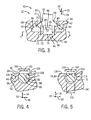
- FIG. 3 is a partial cross-sectional view of an embodiment of the blade mounting system 40 of FIG. 2 , taken within line 3-3, further illustrating details of the sliding joint system 42 and the blade locking system 44.
- the illustrated sliding joint system 42 includes the axial rail 54 of the blade 50 disposed in the axial groove 56 of the rotor 52.
- the configuration may be reversed such that the blade 50 includes the axial groove 56 and the rotor 52 includes the axial rail 54.
- the axial rail 54 may include a neck portion 60 and an enlarged head portion 62, which generally diverges away from the neck portion 60 to form a substantially triangular shaped head portion 62.
- the axial rail 54 may have a T-shaped structure, an L-shaped structure, or the like.
- the axial groove 56 may include an opening 64 along an exterior 66 of the rotor 52, wherein the opening 64 leads into an enlarged cavity 68.
- the enlarged cavity 68 similar to the enlarged head portion 62, generally diverges away from the opening 64 to form a substantially triangular shaped cavity 68.
- the illustrated geometry of the axial rail 54 and axial groove 56 is not intended to be limited, and may be replaced with a variety of other axial joint 54 and 56.
- the blade locking system 44 includes the locking assembly 58 disposed in opposite recesses 71 and 73 in the blade 50 and the rotor 52, respectively.
- the recess 71 is disposed in the axial rail 54 of the blade 50
- the recess 73 is disposed in the axial groove 56 of the rotor 52.
- the recess 71 has a height 70 in the radial direction 32
- the recess 73 has a height 72 in the radial direction 32.
- the height 70 of the recess 71 may be approximately 1 to 50, 2 to 25, or 5 to 10 mm
- the height 72 of the recess 73 may be approximately 1 to 50, 2 to 25, or 5 to 10 mm
- the heights 70 and 72 may be the same or different from one another.
- the height 70 may be approximately 5 to 500, 10 to 250, 20 to 100, or 30 to 50 percent greater than the height 72, or vice versa.
- the different heights 70 and 72 may facilitate operation of the locking assembly 58, as discussed in further detail below.
- the locking assembly 58 includes a first locking insert 74 with a height 76 in the radial direction 32, and a second locking insert 78 with a height 80 in the radial direction 32.
- the first and second locking inserts 74 and 78 are coupled together via a deformation (e.g., staking) 82 of at least one of the inserts 74 or 78.
- the staking 82 is disposed on the first locking insert 74 to secure the second locking insert 78.
- the first locking insert 74 is inserted into the recess 71 in the radial direction 32.
- the blade is coupled to the rotor 52 by axially sliding the axial rail 54 into the axial groove 56 until the recesses 71 and 73 are aligned with one another (i.e., same axial position).
- This is followed by lowering the first locking insert 74 from the recess 71 into the recess 73 in the rotor 52 in the radial direction 32.
- the first locking insert 74 is unable to move in the axial direction 34 and the circumferential direction 30, although the insert 74 can still move in the radial direction 32.
- the height 76 of the first locking insert 74 is greater than the height 72 of the recess 73, such that the first locking insert 74 overlaps both recesses 71 and 73 in the radial direction 32.
- the first locking insert 74 blocks axial movement 34 of the axial rail 54 relative to the axial groove 56 while overlapping the first and second recesses 71 and 73. Nevertheless, the first locking insert 74 is not yet secured in the recesses 71 and 73, as it can still move in the radial direction 32.
- the second locking insert 78 may be inserted into the recess 71 in the axial rail 54 in the axial direction 34, thereby blocking radial movement 32 of the first locking insert 74.
- the sum of the heights 72 and 74 of the recesses 71 and 73 is substantially equal to the sum of the heights 76 and 80 of the first and second locking inserts 74 and 78.
- the inserts 74 and 78 are substantially blocked from moving in the radial direction 32 within the recesses 71 and 73.
- the inserts 74 and 78 are also secured to one another to block axial movement 34.
- the second locking insert 78 may be secured to the first locking insert 74 by deformation of one insert relative to the other.
- the illustrated embodiment depicts the deformation (e.g., staking) 82 disposed on the first locking insert 74, causing a portion 84 of the first locking insert 74 to deform in the radial direction 32 overlapping the second locking insert 78.
- the overlapping portion 84 associated with the deformation (e.g., staking) 82 blocks axial movement 34 of the second locking insert 78, such that the insert 78 remains in place to secure the first locking insert 74.
- the first and second locking inserts 74 and 78 may be coupled together by other mechanisms, such as a welded joint.
- the first and second locking inserts 74 and 78 may be made of a heat resistant material, a corrosion resistant material, a wear resistant material, or a combination thereof.
- the inserts 74 and 78 may be made of various alloys, such as nickel-based steel alloys.
- the inserts 74 and 78 may be used at one or both ends of the sliding joint system 42 for each blade 50.
- the recesses 71 and 73 and the inserts 74 and 78 may have a variety of shapes configured to lock the sliding joint system 42.
- FIG. 4 is a partial cross-sectional view of an embodiment of the blade mounting system 40 of FIG. 3 , taken along line 4-4, further illustrating details of the blade locking system 44 in the sliding joint system 42 (e.g., between the rail 54 and groove 56).
- the first locking insert 74 is depicted within the recess 73 of the rotor 52 after radially 32 lowering the insert 74 from the recess 71 to the recess 73 as discussed above.
- the illustrated recess 73 and first locking insert 74 are shaped to block movement of the insert 74 in the axial direction 34.
- the recess 73 and the insert 74 have a nonuniform width (e.g., variable width) in the axial direction 34, such that the insert 74 cannot be removed from the recess 73 in the axial direction 34.
- the recess 73 and the first locking insert 74 have a first diameter 100 and a second diameter 102 at an axial offset 104 from one another in the axial direction 34, wherein the first diameter 100 is greater than the second diameter 102.
- the first diameter 100 may be approximately 5 to 200, 10 to 100, or 20 to 50 percent greater than the second diameter 102.
- the first and second diameters 100 and 102 may be disposed at a variety of axial locations 34 along the recess 73 and the first locking insert 74.
- the first diameter 100 may be disposed at a generally central or intermediate portion 90 of the recess 73 and the first locking insert 74, while the second diameter 100 may be disposed along an edge portion 92 of the recess 73 and the first locking insert 74.
- the second diameter 102 is disposed along an axial edge 94 of the rotor 52, such that the edge portion 92 of the recess 73 and the first locking insert 74 is disposed along the axial edge 94.
- the recess 73 includes an opening 96 disposed along the axial edge 94 of the rotor 52, and an enlarged cavity 98 disposed within the rotor 52 in an axial inward direction 34 away from the axial edge 94.
- the enlarged cavity 98 has the second diameter 102, while the opening 96 has the first diameter 100.
- the first locking insert 74 includes a neck portion 106 disposed along the axial edge 94 of the rotor 52, and an enlarged body portion 108 disposed within the rotor 52 in an axial inward direction 34 away from the axial edge 94.
- the enlarged body portion 108 has the second diameter 102, while the neck portion 106 has the first diameter 100.
- the recess 73 is a truncated cylindrical recess
- the first locking insert 74 is a truncated cylindrical insert.
- any other shapes may be employed for the recess 73 and insert 74, provided the shapes block axial withdrawal 34 of the insert 74 from the recess 73.
- FIG. 5 is a partial cross-sectional view of an embodiment of the blade mounting system 40 of FIG. 3 , taken along line 5-5, further illustrating details of the blade locking system 44 in the sliding joint system 42 (e.g., between the rail 54 and groove 56).
- the second locking insert 78 is depicted within the recess 71 of the axial rail 54. As illustrated, the second locking insert 78 has a generally rectangular shape, which has a width 110 in the circumferential dimension 30.
- the recess 71 has an opening 112 and an enlarged cavity 114, wherein the opening 112 is disposed along an axial edge 116 of the rail 54 and the cavity 114 is disposed axially inward 34 away from the axial edge 116.
- the illustrated recess 71 is a truncated cylindrical recess with first and second diameters 118 and 120, wherein the second diameter 120 is greater than the first diameter 118.
- the opening 112 of the recess 71 has the first diameter 118, while the enlarged cavity 114 has the second diameter 120.
- the width 110 of the second locking insert 78 is less than the first diameter 118 of the recess 71, thereby enabling insertion and removal of the second locking insert 78 in the axial direction 34.
- the first diameter 118 may be approximately 0 to 20 or 5 to 10 percent larger than the width 110.
- the first locking insert 74 may be deformed (e.g., staked) 82 to extend the portion 84 radially 32 overlapping the second locking insert 78.
- the second locking insert 78 may be axially 34 retained within the recess 71, thereby securing the first locking insert 74.
- the first and second locking inserts 74 and 78 are secured together to block axial movement 34 of the axial rail 54 relative to the axial groove 56.
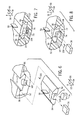
- FIGS. 6 through 9 are partial perspective views of an embodiment of the blade mounting system 40 of FIG. 3 , further illustrating steps of mounting the blade 50 to the rotor 52 using the sliding joint system 42 and the blade locking system 44.
- FIG. 6 is a partial exploded perspective view illustrating an embodiment of the blade 50 having the axial rail 54, the first locking insert 74, and second locking insert 78 exploded from the axial groove 56 in the rotor 52.
- the first locking insert 74 and the recess 71 (similar to the recess 73) have a truncated cylindrical shape, such that the locking insert 74 cannot be inserted or removed in the axial direction 34 relative to the recess 71.
- the first locking insert 74 is inserted into the recess 71 in the radial direction 32, as indicated by arrow 130.
- the axial rail 54 of the blade 50 may be installed in the axial direction 34 into the axial groove 56, as indicated by arrow 132.
- the axial rail 54 is moved axially 34 along the axial groove 56 until the recess 71 of the blade 50 is axially aligned with the recess 73 of the rotor 52, as illustrated in FIG. 7 .
- the first locking insert 74 is lowered from the recess 71 into the recess 73 as indicated by arrow 134.
- the insert 74 may automatically drop into the recess 73 upon axial alignment of the recesses 71 and 73.
- the first locking insert 74 radially overlaps 32 both recesses 71 and 73 in the lowered position of the insert 74, thereby blocking axial movement 34 of the axial rail 54 relative to the axial groove 56.
- the first locking insert 74 is still capable of moving in the radial direction 32, and thus the axial rail 54 is not completely secured to the axial groove 56 at this stage.
- the second locking insert 78 is inserted axially 34 into the recess 71 on top of the first locking insert 74, as indicated by arrow 136.
- FIG. 9 illustrates a deformation (e.g., staking) 82 in the first locking insert 74, which causes the portion 84 of the insert 74 to radially 32 overlap the second locking insert 78.
- the first locking insert 74 blocks axial movement 34 of the axial rail 54 relative to the axial groove 56
- the second locking insert 78 blocks radial movement 32 of the first locking insert 74
- the deformation (e.g., staking) 82 blocks axial movement 34 of the second locking insert 78 relative to the axial rail 54.
- the inserts 74 and 78 completely secure the axial rail 54 to the axial groove 56 without directly staking the rotor 52 or the blade 50.
- FIGS. 10 through 13 are partial cross-sectional views of embodiments of the blade locking system 44 of FIG. 3 , taken along line 4-4; illustrating different locking interfaces between the recess 73 and the first locking insert 74.
- recess 71 of FIG. 3 may have any of the geometric shapes depicted in FIGS. 10 through 13 .
- FIG. 10 illustrates a T-shaped locking interface 140, wherein the recess 73 and the first locking insert 74 both have a T-shaped geometry.
- FIG. 11 illustrates a wedge-shaped locking interface 150, wherein the recess 73 and the first locking insert 74 both have a wedge-shaped geometry.
- FIG. 10 illustrates a T-shaped locking interface 140, wherein the recess 73 and the first locking insert 74 both have a T-shaped geometry.
- FIG. 11 illustrates a wedge-shaped locking interface 150, wherein the recess 73 and the first locking insert 74 both have a wedge-shaped geometry.
- FIG. 10 illustrates a
- FIG. 12 illustrates a bulb-shaped locking interface 160, wherein the recess 73 and the first locking insert 74 both have a bulb-shaped geometry.
- FIG. 13 illustrates an L-shaped locking interface 170, wherein the recess 73 and the first locking insert 74 both have an L-shaped geometry.
- the locking interfaces 140, 150, 160, and 170 block axial movement 34 of the insert 74 relative to the recess 73, while allowing radial movement 32 of the insert 74 relative to the recess 73.
- the second locking insert 78 is subsequently installed to block the radial movement 32 of the first locking insert 74.
- a variety of other shapes may be used for the insert 74 and recess 73 (and recess 71 depicted in FIG. 3 ), provided that the shapes block axial movement 34.
- the disclosed blade locking system 44 enables blades 50 to be installed and secured on a turbomachine 10, such as a compressor.
- a turbomachine 10 such as a compressor.
- the improved design incorporated into the blade locking system enables the turbomachine rotor 52 to retain its supporting shape and not be deformed, even with multiple blade 50 replacements.
- the locking assembly 58 may be deformed.
- the locking assembly 58 may be generally easier to install and cost less than a turbomachine rotor 52.
- the improved design enables the turbomachine rotor 52 to have an increased usable life and reduced costs associated therewith.
- the improved design enables turbomachine blades 50 to be replaced when needed.
Landscapes
- Engineering & Computer Science (AREA)
- Mechanical Engineering (AREA)
- General Engineering & Computer Science (AREA)
- Turbine Rotor Nozzle Sealing (AREA)
- Structures Of Non-Positive Displacement Pumps (AREA)
Applications Claiming Priority (1)
| Application Number | Priority Date | Filing Date | Title |
|---|---|---|---|
| US13/157,241 US8764402B2 (en) | 2011-06-09 | 2011-06-09 | Turbomachine blade locking system |
Publications (3)
| Publication Number | Publication Date |
|---|---|
| EP2532835A2 true EP2532835A2 (fr) | 2012-12-12 |
| EP2532835A3 EP2532835A3 (fr) | 2013-08-07 |
| EP2532835B1 EP2532835B1 (fr) | 2016-05-25 |
Family
ID=46208334
Family Applications (1)
| Application Number | Title | Priority Date | Filing Date |
|---|---|---|---|
| EP12170316.9A Active EP2532835B1 (fr) | 2011-06-09 | 2012-05-31 | Système de verrouillage d'aube de turbomachine |
Country Status (3)
| Country | Link |
|---|---|
| US (1) | US8764402B2 (fr) |
| EP (1) | EP2532835B1 (fr) |
| CN (2) | CN105525950B (fr) |
Cited By (2)
| Publication number | Priority date | Publication date | Assignee | Title |
|---|---|---|---|---|
| EP3375979A1 (fr) * | 2017-03-16 | 2018-09-19 | Doosan Heavy Industries & Construction Co., Ltd. | Appareil de verrouillage axial d'aube et ensemble d'aubes et turbine à gaz les comprenant |
| EP3382154A1 (fr) * | 2017-03-31 | 2018-10-03 | Doosan Heavy Industries & Construction Co., Ltd. | Unité tournante et turbine à vapeur la comprenant |
Families Citing this family (13)
| Publication number | Priority date | Publication date | Assignee | Title |
|---|---|---|---|---|
| FR2963383B1 (fr) * | 2010-07-27 | 2016-09-09 | Snecma | Aube de turbomachine, rotor, turbine basse pression et turbomachine equipes d'une telle aube |
| JP5922370B2 (ja) * | 2011-10-20 | 2016-05-24 | 三菱日立パワーシステムズ株式会社 | 動翼支持構造 |
| US9624780B2 (en) * | 2013-12-17 | 2017-04-18 | General Electric Company | System and method for securing axially inserted buckets to a rotor assembly |
| FR3031136B1 (fr) * | 2014-12-26 | 2019-11-01 | Safran Aircraft Engines | Rotor de turbomachine a surfaces d'appui optimisees |
| US10400784B2 (en) * | 2015-05-27 | 2019-09-03 | United Technologies Corporation | Fan blade attachment root with improved strain response |
| US9506357B1 (en) | 2015-12-08 | 2016-11-29 | General Electric Company | Turbomachine staking tool |
| US20180030882A1 (en) * | 2016-07-26 | 2018-02-01 | Caterpillar Inc. | Coupling mechanism |
| US20180058247A1 (en) * | 2016-08-23 | 2018-03-01 | Borgwarner Inc. | Vane actuator and method of making and using the same |
| KR102095033B1 (ko) * | 2017-05-30 | 2020-03-30 | 두산중공업 주식회사 | 베인 링 조립체 및 이를 포함하는 압축기, 가스터빈 |
| US11339674B2 (en) | 2018-08-14 | 2022-05-24 | Rolls-Royce North American Technologies Inc. | Blade retainer for gas turbine engine |
| CN110397625A (zh) * | 2019-08-15 | 2019-11-01 | 上海电气燃气轮机有限公司 | 一种新型叶片锁紧装置 |
| KR102454379B1 (ko) * | 2020-09-08 | 2022-10-14 | 두산에너빌리티 주식회사 | 로터 및 이를 포함하는 터보머신 |
| US12221899B2 (en) * | 2023-06-15 | 2025-02-11 | General Electric Company | Methods and apparatuses for blade locking |
Family Cites Families (16)
| Publication number | Priority date | Publication date | Assignee | Title |
|---|---|---|---|---|
| US3383095A (en) * | 1967-09-12 | 1968-05-14 | Gen Electric | Lock for turbomachinery blades |
| FR2507679A1 (fr) | 1981-06-12 | 1982-12-17 | Snecma | Dispositif de verrouillage d'une aube de rotor de turbomachine |
| US4820127A (en) | 1988-01-29 | 1989-04-11 | Westinghouse Electric Corp. | Blade support and blade assembly |
| US4836749A (en) * | 1988-02-19 | 1989-06-06 | Westinghouse Electric Corp. | Pre-load device for a turbomachine rotor |
| DE4430636C2 (de) * | 1994-08-29 | 1997-01-23 | Mtu Muenchen Gmbh | Einrichtung zur Laufschaufelfixierung und zur Beseitigung von Rotorunwuchten bei axial durchströmten Verdichtern oder Turbinen von Gasturbinentriebwerken |
| US5713721A (en) | 1996-05-09 | 1998-02-03 | General Electric Co. | Retention system for the blades of a rotary machine |
| US5720596A (en) | 1997-01-03 | 1998-02-24 | Westinghouse Electric Corporation | Apparatus and method for locking blades into a rotor |
| EP1584791A1 (fr) | 2004-04-07 | 2005-10-12 | Siemens Aktiengesellschaft | Turbomachine et rotor pour turbomachine |
| DE102004017193A1 (de) | 2004-04-07 | 2005-10-27 | Rolls-Royce Deutschland Ltd & Co Kg | Turbinenschaufelarretiervorrichtung |
| DE602005005988T2 (de) * | 2005-08-12 | 2009-05-20 | Siemens Aktiengesellschaft | Turbine für eine Wärmekraftanlage mit Haltevorrichtung |
| EP1803899A1 (fr) * | 2006-01-02 | 2007-07-04 | Siemens Aktiengesellschaft | Ensemble de verrouillage d'aube pour une turbomachine |
| EP1860280A1 (fr) * | 2006-04-07 | 2007-11-28 | Siemens Aktiengesellschaft | Dispositif de verrouillage d'une aube de turbine comprenant un élément de verrouillage |
| DE602006006452D1 (de) * | 2006-09-25 | 2009-06-04 | Siemens Ag | Turbinenrotor mit Verschlussplatten und entsprechendes Montageverfahren |
| US20080273982A1 (en) | 2007-03-12 | 2008-11-06 | Honeywell International, Inc. | Blade attachment retention device |
| US8142161B2 (en) | 2007-09-20 | 2012-03-27 | General Electric Company | Replaceable staking insert |
| US8061995B2 (en) * | 2008-01-10 | 2011-11-22 | General Electric Company | Machine component retention |
-
2011
- 2011-06-09 US US13/157,241 patent/US8764402B2/en active Active
-
2012
- 2012-05-31 EP EP12170316.9A patent/EP2532835B1/fr active Active
- 2012-06-08 CN CN201510949684.4A patent/CN105525950B/zh active Active
- 2012-06-08 CN CN201210189630.9A patent/CN102817640B/zh active Active
Non-Patent Citations (1)
| Title |
|---|
| None |
Cited By (4)
| Publication number | Priority date | Publication date | Assignee | Title |
|---|---|---|---|---|
| EP3375979A1 (fr) * | 2017-03-16 | 2018-09-19 | Doosan Heavy Industries & Construction Co., Ltd. | Appareil de verrouillage axial d'aube et ensemble d'aubes et turbine à gaz les comprenant |
| US10934864B2 (en) | 2017-03-16 | 2021-03-02 | DOOSAN Heavy Industries Construction Co., LTD | Apparatus for axial locking of bucket and bucket assembly and gas turbine having the same |
| EP3382154A1 (fr) * | 2017-03-31 | 2018-10-03 | Doosan Heavy Industries & Construction Co., Ltd. | Unité tournante et turbine à vapeur la comprenant |
| US10871076B2 (en) | 2017-03-31 | 2020-12-22 | DOOSAN Heavy Industries Construction Co., LTD | Rotating unit and steam turbine including the same |
Also Published As
| Publication number | Publication date |
|---|---|
| EP2532835A3 (fr) | 2013-08-07 |
| CN105525950A (zh) | 2016-04-27 |
| CN102817640A (zh) | 2012-12-12 |
| US20120315144A1 (en) | 2012-12-13 |
| EP2532835B1 (fr) | 2016-05-25 |
| CN105525950B (zh) | 2017-08-29 |
| CN102817640B (zh) | 2016-02-24 |
| US8764402B2 (en) | 2014-07-01 |
Similar Documents
| Publication | Publication Date | Title |
|---|---|---|
| US8764402B2 (en) | Turbomachine blade locking system | |
| EP2613000B1 (fr) | Système de rétention axiale de segments rotatifs d'une turbine et procedé associé | |
| US10309240B2 (en) | Method and system for interfacing a ceramic matrix composite component to a metallic component | |
| JP6141871B2 (ja) | 高温気体膨張装置の入口ケーシング組立体及び方法 | |
| US20120036857A1 (en) | Combustion liner stop blocks having insertable wear features and related methods | |
| US8776347B2 (en) | Tool for rotor assembly and disassembly | |
| CN105781625B (zh) | 用于安装涡轮动叶的卡具和方法 | |
| JP2013160229A (ja) | タービンの冷却材流路のシールアセンブリ | |
| US10094244B2 (en) | Ceramic matrix composite ring shroud retention methods-wiggle strip spring seal | |
| EP3168424A1 (fr) | Mécanisme de fixation de lame de turbine | |
| EP2447475A2 (fr) | Agencement de fixation d'une aube | |
| US20100064516A1 (en) | Stator Ring Configuration | |
| WO2009058629A1 (fr) | Remise en état d'aube de stator compresseur de tige | |
| EP2904241B1 (fr) | Dispositif anti-erreur de joint d'étanchéité de chambre de combustion de turbine à gaz | |
| EP3179046A1 (fr) | Pinces thermiques en cmc | |
| EP3144482A1 (fr) | Procédés de rétention à anneau d'étanchéité composite à matrice céramique (cmc) - tête d'épingle en cmc | |
| EP2581559A2 (fr) | Ensemble adaptateur pour accouplement d'aubes de turbine au disque rotor | |
| EP3144488A1 (fr) | Dispositif de retenue de virole d'une turbine | |
| EP3421408B1 (fr) | Ensemble de manipulation de composant de turbomachine | |
| EP2554800A2 (fr) | Procédés et dispositif pour modifier un carter de turbine | |
| EP2564979A2 (fr) | Douille pour réparer un anneau à bride circonférentiel | |
| US12460727B2 (en) | Self-centering seal and method of using same | |
| US20140030083A1 (en) | Article of manufacture for turbomachine | |
| US20130108449A1 (en) | System for coupling a segment to a rotor of a turbomachine | |
| US20240318562A1 (en) | Turbine tip shroud removal feature |
Legal Events
| Date | Code | Title | Description |
|---|---|---|---|
| PUAI | Public reference made under article 153(3) epc to a published international application that has entered the european phase |
Free format text: ORIGINAL CODE: 0009012 |
|
| AK | Designated contracting states |
Kind code of ref document: A2 Designated state(s): AL AT BE BG CH CY CZ DE DK EE ES FI FR GB GR HR HU IE IS IT LI LT LU LV MC MK MT NL NO PL PT RO RS SE SI SK SM TR |
|
| AX | Request for extension of the european patent |
Extension state: BA ME |
|
| PUAL | Search report despatched |
Free format text: ORIGINAL CODE: 0009013 |
|
| AK | Designated contracting states |
Kind code of ref document: A3 Designated state(s): AL AT BE BG CH CY CZ DE DK EE ES FI FR GB GR HR HU IE IS IT LI LT LU LV MC MK MT NL NO PL PT RO RS SE SI SK SM TR |
|
| AX | Request for extension of the european patent |
Extension state: BA ME |
|
| RIC1 | Information provided on ipc code assigned before grant |
Ipc: F01D 5/30 20060101ALI20130702BHEP Ipc: F01D 5/32 20060101AFI20130702BHEP |
|
| 17P | Request for examination filed |
Effective date: 20140207 |
|
| RBV | Designated contracting states (corrected) |
Designated state(s): AL AT BE BG CH CY CZ DE DK EE ES FI FR GB GR HR HU IE IS IT LI LT LU LV MC MK MT NL NO PL PT RO RS SE SI SK SM TR |
|
| 17Q | First examination report despatched |
Effective date: 20140321 |
|
| GRAP | Despatch of communication of intention to grant a patent |
Free format text: ORIGINAL CODE: EPIDOSNIGR1 |
|
| INTG | Intention to grant announced |
Effective date: 20160111 |
|
| GRAS | Grant fee paid |
Free format text: ORIGINAL CODE: EPIDOSNIGR3 |
|
| GRAA | (expected) grant |
Free format text: ORIGINAL CODE: 0009210 |
|
| AK | Designated contracting states |
Kind code of ref document: B1 Designated state(s): AL AT BE BG CH CY CZ DE DK EE ES FI FR GB GR HR HU IE IS IT LI LT LU LV MC MK MT NL NO PL PT RO RS SE SI SK SM TR |
|
| REG | Reference to a national code |
Ref country code: GB Ref legal event code: FG4D |
|
| REG | Reference to a national code |
Ref country code: CH Ref legal event code: EP |
|
| REG | Reference to a national code |
Ref country code: IE Ref legal event code: FG4D Ref country code: AT Ref legal event code: REF Ref document number: 802508 Country of ref document: AT Kind code of ref document: T Effective date: 20160615 |
|
| REG | Reference to a national code |
Ref country code: FR Ref legal event code: PLFP Year of fee payment: 5 |
|
| REG | Reference to a national code |
Ref country code: DE Ref legal event code: R096 Ref document number: 602012018882 Country of ref document: DE |
|
| REG | Reference to a national code |
Ref country code: LT Ref legal event code: MG4D |
|
| REG | Reference to a national code |
Ref country code: NL Ref legal event code: MP Effective date: 20160525 |
|
| PG25 | Lapsed in a contracting state [announced via postgrant information from national office to epo] |
Ref country code: FI Free format text: LAPSE BECAUSE OF FAILURE TO SUBMIT A TRANSLATION OF THE DESCRIPTION OR TO PAY THE FEE WITHIN THE PRESCRIBED TIME-LIMIT Effective date: 20160525 Ref country code: NO Free format text: LAPSE BECAUSE OF FAILURE TO SUBMIT A TRANSLATION OF THE DESCRIPTION OR TO PAY THE FEE WITHIN THE PRESCRIBED TIME-LIMIT Effective date: 20160825 Ref country code: LT Free format text: LAPSE BECAUSE OF FAILURE TO SUBMIT A TRANSLATION OF THE DESCRIPTION OR TO PAY THE FEE WITHIN THE PRESCRIBED TIME-LIMIT Effective date: 20160525 Ref country code: NL Free format text: LAPSE BECAUSE OF FAILURE TO SUBMIT A TRANSLATION OF THE DESCRIPTION OR TO PAY THE FEE WITHIN THE PRESCRIBED TIME-LIMIT Effective date: 20160525 |
|
| REG | Reference to a national code |
Ref country code: AT Ref legal event code: MK05 Ref document number: 802508 Country of ref document: AT Kind code of ref document: T Effective date: 20160525 |
|
| PG25 | Lapsed in a contracting state [announced via postgrant information from national office to epo] |
Ref country code: GR Free format text: LAPSE BECAUSE OF FAILURE TO SUBMIT A TRANSLATION OF THE DESCRIPTION OR TO PAY THE FEE WITHIN THE PRESCRIBED TIME-LIMIT Effective date: 20160826 Ref country code: ES Free format text: LAPSE BECAUSE OF FAILURE TO SUBMIT A TRANSLATION OF THE DESCRIPTION OR TO PAY THE FEE WITHIN THE PRESCRIBED TIME-LIMIT Effective date: 20160525 Ref country code: PT Free format text: LAPSE BECAUSE OF FAILURE TO SUBMIT A TRANSLATION OF THE DESCRIPTION OR TO PAY THE FEE WITHIN THE PRESCRIBED TIME-LIMIT Effective date: 20160926 Ref country code: SE Free format text: LAPSE BECAUSE OF FAILURE TO SUBMIT A TRANSLATION OF THE DESCRIPTION OR TO PAY THE FEE WITHIN THE PRESCRIBED TIME-LIMIT Effective date: 20160525 Ref country code: LV Free format text: LAPSE BECAUSE OF FAILURE TO SUBMIT A TRANSLATION OF THE DESCRIPTION OR TO PAY THE FEE WITHIN THE PRESCRIBED TIME-LIMIT Effective date: 20160525 Ref country code: RS Free format text: LAPSE BECAUSE OF FAILURE TO SUBMIT A TRANSLATION OF THE DESCRIPTION OR TO PAY THE FEE WITHIN THE PRESCRIBED TIME-LIMIT Effective date: 20160525 |
|
| PG25 | Lapsed in a contracting state [announced via postgrant information from national office to epo] |
Ref country code: BE Free format text: LAPSE BECAUSE OF NON-PAYMENT OF DUE FEES Effective date: 20160531 |
|
| PG25 | Lapsed in a contracting state [announced via postgrant information from national office to epo] |
Ref country code: RO Free format text: LAPSE BECAUSE OF FAILURE TO SUBMIT A TRANSLATION OF THE DESCRIPTION OR TO PAY THE FEE WITHIN THE PRESCRIBED TIME-LIMIT Effective date: 20160525 Ref country code: DK Free format text: LAPSE BECAUSE OF FAILURE TO SUBMIT A TRANSLATION OF THE DESCRIPTION OR TO PAY THE FEE WITHIN THE PRESCRIBED TIME-LIMIT Effective date: 20160525 Ref country code: EE Free format text: LAPSE BECAUSE OF FAILURE TO SUBMIT A TRANSLATION OF THE DESCRIPTION OR TO PAY THE FEE WITHIN THE PRESCRIBED TIME-LIMIT Effective date: 20160525 Ref country code: SK Free format text: LAPSE BECAUSE OF FAILURE TO SUBMIT A TRANSLATION OF THE DESCRIPTION OR TO PAY THE FEE WITHIN THE PRESCRIBED TIME-LIMIT Effective date: 20160525 Ref country code: CZ Free format text: LAPSE BECAUSE OF FAILURE TO SUBMIT A TRANSLATION OF THE DESCRIPTION OR TO PAY THE FEE WITHIN THE PRESCRIBED TIME-LIMIT Effective date: 20160525 |
|
| REG | Reference to a national code |
Ref country code: IE Ref legal event code: MM4A |
|
| PG25 | Lapsed in a contracting state [announced via postgrant information from national office to epo] |
Ref country code: BE Free format text: LAPSE BECAUSE OF FAILURE TO SUBMIT A TRANSLATION OF THE DESCRIPTION OR TO PAY THE FEE WITHIN THE PRESCRIBED TIME-LIMIT Effective date: 20160525 Ref country code: AT Free format text: LAPSE BECAUSE OF FAILURE TO SUBMIT A TRANSLATION OF THE DESCRIPTION OR TO PAY THE FEE WITHIN THE PRESCRIBED TIME-LIMIT Effective date: 20160525 Ref country code: PL Free format text: LAPSE BECAUSE OF FAILURE TO SUBMIT A TRANSLATION OF THE DESCRIPTION OR TO PAY THE FEE WITHIN THE PRESCRIBED TIME-LIMIT Effective date: 20160525 Ref country code: SM Free format text: LAPSE BECAUSE OF FAILURE TO SUBMIT A TRANSLATION OF THE DESCRIPTION OR TO PAY THE FEE WITHIN THE PRESCRIBED TIME-LIMIT Effective date: 20160525 |
|
| REG | Reference to a national code |
Ref country code: DE Ref legal event code: R097 Ref document number: 602012018882 Country of ref document: DE |
|
| PG25 | Lapsed in a contracting state [announced via postgrant information from national office to epo] |
Ref country code: MC Free format text: LAPSE BECAUSE OF FAILURE TO SUBMIT A TRANSLATION OF THE DESCRIPTION OR TO PAY THE FEE WITHIN THE PRESCRIBED TIME-LIMIT Effective date: 20160525 |
|
| PLBE | No opposition filed within time limit |
Free format text: ORIGINAL CODE: 0009261 |
|
| STAA | Information on the status of an ep patent application or granted ep patent |
Free format text: STATUS: NO OPPOSITION FILED WITHIN TIME LIMIT |
|
| GBPC | Gb: european patent ceased through non-payment of renewal fee |
Effective date: 20160825 |
|
| 26N | No opposition filed |
Effective date: 20170228 |
|
| REG | Reference to a national code |
Ref country code: FR Ref legal event code: PLFP Year of fee payment: 6 |
|
| PG25 | Lapsed in a contracting state [announced via postgrant information from national office to epo] |
Ref country code: IE Free format text: LAPSE BECAUSE OF NON-PAYMENT OF DUE FEES Effective date: 20160531 Ref country code: SI Free format text: LAPSE BECAUSE OF FAILURE TO SUBMIT A TRANSLATION OF THE DESCRIPTION OR TO PAY THE FEE WITHIN THE PRESCRIBED TIME-LIMIT Effective date: 20160525 |
|
| PG25 | Lapsed in a contracting state [announced via postgrant information from national office to epo] |
Ref country code: GB Free format text: LAPSE BECAUSE OF NON-PAYMENT OF DUE FEES Effective date: 20160825 |
|
| REG | Reference to a national code |
Ref country code: FR Ref legal event code: PLFP Year of fee payment: 7 |
|
| PG25 | Lapsed in a contracting state [announced via postgrant information from national office to epo] |
Ref country code: CY Free format text: LAPSE BECAUSE OF FAILURE TO SUBMIT A TRANSLATION OF THE DESCRIPTION OR TO PAY THE FEE WITHIN THE PRESCRIBED TIME-LIMIT Effective date: 20160525 Ref country code: HU Free format text: LAPSE BECAUSE OF FAILURE TO SUBMIT A TRANSLATION OF THE DESCRIPTION OR TO PAY THE FEE WITHIN THE PRESCRIBED TIME-LIMIT; INVALID AB INITIO Effective date: 20120531 |
|
| PG25 | Lapsed in a contracting state [announced via postgrant information from national office to epo] |
Ref country code: LU Free format text: LAPSE BECAUSE OF NON-PAYMENT OF DUE FEES Effective date: 20160531 Ref country code: TR Free format text: LAPSE BECAUSE OF FAILURE TO SUBMIT A TRANSLATION OF THE DESCRIPTION OR TO PAY THE FEE WITHIN THE PRESCRIBED TIME-LIMIT Effective date: 20160525 Ref country code: MT Free format text: LAPSE BECAUSE OF NON-PAYMENT OF DUE FEES Effective date: 20160531 Ref country code: MK Free format text: LAPSE BECAUSE OF FAILURE TO SUBMIT A TRANSLATION OF THE DESCRIPTION OR TO PAY THE FEE WITHIN THE PRESCRIBED TIME-LIMIT Effective date: 20160525 Ref country code: IS Free format text: LAPSE BECAUSE OF FAILURE TO SUBMIT A TRANSLATION OF THE DESCRIPTION OR TO PAY THE FEE WITHIN THE PRESCRIBED TIME-LIMIT Effective date: 20160525 Ref country code: HR Free format text: LAPSE BECAUSE OF FAILURE TO SUBMIT A TRANSLATION OF THE DESCRIPTION OR TO PAY THE FEE WITHIN THE PRESCRIBED TIME-LIMIT Effective date: 20160525 |
|
| PG25 | Lapsed in a contracting state [announced via postgrant information from national office to epo] |
Ref country code: BG Free format text: LAPSE BECAUSE OF FAILURE TO SUBMIT A TRANSLATION OF THE DESCRIPTION OR TO PAY THE FEE WITHIN THE PRESCRIBED TIME-LIMIT Effective date: 20160525 |
|
| PG25 | Lapsed in a contracting state [announced via postgrant information from national office to epo] |
Ref country code: AL Free format text: LAPSE BECAUSE OF FAILURE TO SUBMIT A TRANSLATION OF THE DESCRIPTION OR TO PAY THE FEE WITHIN THE PRESCRIBED TIME-LIMIT Effective date: 20160525 |
|
| PGFP | Annual fee paid to national office [announced via postgrant information from national office to epo] |
Ref country code: CH Payment date: 20190419 Year of fee payment: 8 |
|
| PGFP | Annual fee paid to national office [announced via postgrant information from national office to epo] |
Ref country code: FR Payment date: 20200422 Year of fee payment: 9 |
|
| PG25 | Lapsed in a contracting state [announced via postgrant information from national office to epo] |
Ref country code: LI Free format text: LAPSE BECAUSE OF NON-PAYMENT OF DUE FEES Effective date: 20200531 Ref country code: CH Free format text: LAPSE BECAUSE OF NON-PAYMENT OF DUE FEES Effective date: 20200531 |
|
| PG25 | Lapsed in a contracting state [announced via postgrant information from national office to epo] |
Ref country code: FR Free format text: LAPSE BECAUSE OF NON-PAYMENT OF DUE FEES Effective date: 20210531 |
|
| REG | Reference to a national code |
Ref country code: DE Ref legal event code: R081 Ref document number: 602012018882 Country of ref document: DE Owner name: GENERAL ELECTRIC TECHNOLOGY GMBH, CH Free format text: FORMER OWNER: GENERAL ELECTRIC COMPANY, SCHENECTADY, NY, US |
|
| PGFP | Annual fee paid to national office [announced via postgrant information from national office to epo] |
Ref country code: DE Payment date: 20250423 Year of fee payment: 14 |
|
| PGFP | Annual fee paid to national office [announced via postgrant information from national office to epo] |
Ref country code: IT Payment date: 20250423 Year of fee payment: 14 |