EP2532867A2 - Abgasrückführungssystem für eine Brennkraftmaschine - Google Patents
Abgasrückführungssystem für eine Brennkraftmaschine Download PDFInfo
- Publication number
- EP2532867A2 EP2532867A2 EP12170322A EP12170322A EP2532867A2 EP 2532867 A2 EP2532867 A2 EP 2532867A2 EP 12170322 A EP12170322 A EP 12170322A EP 12170322 A EP12170322 A EP 12170322A EP 2532867 A2 EP2532867 A2 EP 2532867A2
- Authority
- EP
- European Patent Office
- Prior art keywords
- exhaust gas
- intake air
- gas recirculation
- passage
- pressure
- Prior art date
- Legal status (The legal status is an assumption and is not a legal conclusion. Google has not performed a legal analysis and makes no representation as to the accuracy of the status listed.)
- Granted
Links
Images



Classifications
-
- F—MECHANICAL ENGINEERING; LIGHTING; HEATING; WEAPONS; BLASTING
- F02—COMBUSTION ENGINES; HOT-GAS OR COMBUSTION-PRODUCT ENGINE PLANTS
- F02D—CONTROLLING COMBUSTION ENGINES
- F02D41/00—Electrical control of supply of combustible mixture or its constituents
- F02D41/0025—Controlling engines characterised by use of non-liquid fuels, pluralities of fuels, or non-fuel substances added to the combustible mixtures
- F02D41/0047—Controlling exhaust gas recirculation [EGR]
- F02D41/0065—Specific aspects of external EGR control
-
- F—MECHANICAL ENGINEERING; LIGHTING; HEATING; WEAPONS; BLASTING
- F02—COMBUSTION ENGINES; HOT-GAS OR COMBUSTION-PRODUCT ENGINE PLANTS
- F02D—CONTROLLING COMBUSTION ENGINES
- F02D21/00—Controlling engines characterised by their being supplied with non-airborne oxygen or other non-fuel gas
- F02D21/06—Controlling engines characterised by their being supplied with non-airborne oxygen or other non-fuel gas peculiar to engines having other non-fuel gas added to combustion air
- F02D21/08—Controlling engines characterised by their being supplied with non-airborne oxygen or other non-fuel gas peculiar to engines having other non-fuel gas added to combustion air the other gas being the exhaust gas of engine
-
- F—MECHANICAL ENGINEERING; LIGHTING; HEATING; WEAPONS; BLASTING
- F02—COMBUSTION ENGINES; HOT-GAS OR COMBUSTION-PRODUCT ENGINE PLANTS
- F02D—CONTROLLING COMBUSTION ENGINES
- F02D41/00—Electrical control of supply of combustible mixture or its constituents
- F02D41/0025—Controlling engines characterised by use of non-liquid fuels, pluralities of fuels, or non-fuel substances added to the combustible mixtures
- F02D41/0047—Controlling exhaust gas recirculation [EGR]
- F02D41/0077—Control of the EGR valve or actuator, e.g. duty cycle, closed loop control of position
-
- F—MECHANICAL ENGINEERING; LIGHTING; HEATING; WEAPONS; BLASTING
- F02—COMBUSTION ENGINES; HOT-GAS OR COMBUSTION-PRODUCT ENGINE PLANTS
- F02D—CONTROLLING COMBUSTION ENGINES
- F02D41/00—Electrical control of supply of combustible mixture or its constituents
- F02D41/02—Circuit arrangements for generating control signals
- F02D41/14—Introducing closed-loop corrections
- F02D41/1438—Introducing closed-loop corrections using means for determining characteristics of the combustion gases; Sensors therefor
- F02D41/1444—Introducing closed-loop corrections using means for determining characteristics of the combustion gases; Sensors therefor characterised by the characteristics of the combustion gases
- F02D41/1448—Introducing closed-loop corrections using means for determining characteristics of the combustion gases; Sensors therefor characterised by the characteristics of the combustion gases the characteristics being an exhaust gas pressure
- F02D41/145—Introducing closed-loop corrections using means for determining characteristics of the combustion gases; Sensors therefor characterised by the characteristics of the combustion gases the characteristics being an exhaust gas pressure with determination means using an estimation
-
- F—MECHANICAL ENGINEERING; LIGHTING; HEATING; WEAPONS; BLASTING
- F02—COMBUSTION ENGINES; HOT-GAS OR COMBUSTION-PRODUCT ENGINE PLANTS
- F02D—CONTROLLING COMBUSTION ENGINES
- F02D41/00—Electrical control of supply of combustible mixture or its constituents
- F02D41/02—Circuit arrangements for generating control signals
- F02D41/14—Introducing closed-loop corrections
- F02D41/1401—Introducing closed-loop corrections characterised by the control or regulation method
- F02D2041/1413—Controller structures or design
- F02D2041/1431—Controller structures or design the system including an input-output delay
-
- F—MECHANICAL ENGINEERING; LIGHTING; HEATING; WEAPONS; BLASTING
- F02—COMBUSTION ENGINES; HOT-GAS OR COMBUSTION-PRODUCT ENGINE PLANTS
- F02D—CONTROLLING COMBUSTION ENGINES
- F02D2200/00—Input parameters for engine control
- F02D2200/02—Input parameters for engine control the parameters being related to the engine
- F02D2200/04—Engine intake system parameters
- F02D2200/0406—Intake manifold pressure
- F02D2200/0408—Estimation of intake manifold pressure
-
- F—MECHANICAL ENGINEERING; LIGHTING; HEATING; WEAPONS; BLASTING
- F02—COMBUSTION ENGINES; HOT-GAS OR COMBUSTION-PRODUCT ENGINE PLANTS
- F02D—CONTROLLING COMBUSTION ENGINES
- F02D41/00—Electrical control of supply of combustible mixture or its constituents
- F02D41/02—Circuit arrangements for generating control signals
- F02D41/18—Circuit arrangements for generating control signals by measuring intake air flow
-
- F—MECHANICAL ENGINEERING; LIGHTING; HEATING; WEAPONS; BLASTING
- F02—COMBUSTION ENGINES; HOT-GAS OR COMBUSTION-PRODUCT ENGINE PLANTS
- F02M—SUPPLYING COMBUSTION ENGINES IN GENERAL WITH COMBUSTIBLE MIXTURES OR CONSTITUENTS THEREOF
- F02M26/00—Engine-pertinent apparatus for adding exhaust gases to combustion-air, main fuel or fuel-air mixture, e.g. by exhaust gas recirculation [EGR] systems
- F02M26/02—EGR systems specially adapted for supercharged engines
- F02M26/04—EGR systems specially adapted for supercharged engines with a single turbocharger
- F02M26/05—High pressure loops, i.e. wherein recirculated exhaust gas is taken out from the exhaust system upstream of the turbine and reintroduced into the intake system downstream of the compressor
-
- F—MECHANICAL ENGINEERING; LIGHTING; HEATING; WEAPONS; BLASTING
- F02—COMBUSTION ENGINES; HOT-GAS OR COMBUSTION-PRODUCT ENGINE PLANTS
- F02M—SUPPLYING COMBUSTION ENGINES IN GENERAL WITH COMBUSTIBLE MIXTURES OR CONSTITUENTS THEREOF
- F02M26/00—Engine-pertinent apparatus for adding exhaust gases to combustion-air, main fuel or fuel-air mixture, e.g. by exhaust gas recirculation [EGR] systems
- F02M26/02—EGR systems specially adapted for supercharged engines
- F02M26/04—EGR systems specially adapted for supercharged engines with a single turbocharger
- F02M26/06—Low pressure loops, i.e. wherein recirculated exhaust gas is taken out from the exhaust downstream of the turbocharger turbine and reintroduced into the intake system upstream of the compressor
-
- F—MECHANICAL ENGINEERING; LIGHTING; HEATING; WEAPONS; BLASTING
- F02—COMBUSTION ENGINES; HOT-GAS OR COMBUSTION-PRODUCT ENGINE PLANTS
- F02M—SUPPLYING COMBUSTION ENGINES IN GENERAL WITH COMBUSTIBLE MIXTURES OR CONSTITUENTS THEREOF
- F02M26/00—Engine-pertinent apparatus for adding exhaust gases to combustion-air, main fuel or fuel-air mixture, e.g. by exhaust gas recirculation [EGR] systems
- F02M26/13—Arrangement or layout of EGR passages, e.g. in relation to specific engine parts or for incorporation of accessories
- F02M26/22—Arrangement or layout of EGR passages, e.g. in relation to specific engine parts or for incorporation of accessories with coolers in the recirculation passage
- F02M26/23—Layout, e.g. schematics
-
- F—MECHANICAL ENGINEERING; LIGHTING; HEATING; WEAPONS; BLASTING
- F02—COMBUSTION ENGINES; HOT-GAS OR COMBUSTION-PRODUCT ENGINE PLANTS
- F02M—SUPPLYING COMBUSTION ENGINES IN GENERAL WITH COMBUSTIBLE MIXTURES OR CONSTITUENTS THEREOF
- F02M26/00—Engine-pertinent apparatus for adding exhaust gases to combustion-air, main fuel or fuel-air mixture, e.g. by exhaust gas recirculation [EGR] systems
- F02M26/13—Arrangement or layout of EGR passages, e.g. in relation to specific engine parts or for incorporation of accessories
- F02M26/22—Arrangement or layout of EGR passages, e.g. in relation to specific engine parts or for incorporation of accessories with coolers in the recirculation passage
- F02M26/33—Arrangement or layout of EGR passages, e.g. in relation to specific engine parts or for incorporation of accessories with coolers in the recirculation passage controlling the temperature of the recirculated gases
-
- F—MECHANICAL ENGINEERING; LIGHTING; HEATING; WEAPONS; BLASTING
- F02—COMBUSTION ENGINES; HOT-GAS OR COMBUSTION-PRODUCT ENGINE PLANTS
- F02M—SUPPLYING COMBUSTION ENGINES IN GENERAL WITH COMBUSTIBLE MIXTURES OR CONSTITUENTS THEREOF
- F02M26/00—Engine-pertinent apparatus for adding exhaust gases to combustion-air, main fuel or fuel-air mixture, e.g. by exhaust gas recirculation [EGR] systems
- F02M26/45—Sensors specially adapted for EGR systems
- F02M26/46—Sensors specially adapted for EGR systems for determining the characteristics of gases, e.g. composition
- F02M26/47—Sensors specially adapted for EGR systems for determining the characteristics of gases, e.g. composition the characteristics being temperatures, pressures or flow rates
-
- Y—GENERAL TAGGING OF NEW TECHNOLOGICAL DEVELOPMENTS; GENERAL TAGGING OF CROSS-SECTIONAL TECHNOLOGIES SPANNING OVER SEVERAL SECTIONS OF THE IPC; TECHNICAL SUBJECTS COVERED BY FORMER USPC CROSS-REFERENCE ART COLLECTIONS [XRACs] AND DIGESTS
- Y02—TECHNOLOGIES OR APPLICATIONS FOR MITIGATION OR ADAPTATION AGAINST CLIMATE CHANGE
- Y02T—CLIMATE CHANGE MITIGATION TECHNOLOGIES RELATED TO TRANSPORTATION
- Y02T10/00—Road transport of goods or passengers
- Y02T10/10—Internal combustion engine [ICE] based vehicles
- Y02T10/40—Engine management systems
Definitions
- This disclosure generally relates to an exhaust gas recirculation (EGR) system for an internal combustion engine.
- EGR exhaust gas recirculation
- Patent Document 1 a cooling system of EGR for an internal combustion engine in which an EGR control during a quick acceleration may be effectively performed. Specifically, an estimate or virtual EGR rate is calculated based on a pressure difference across an EGR valve. In addition, a target EGR rate is calculated from engine rotational speed. A difference between the virtual EGR rate and the target EGR rate is used to correct an EGR valve opening.
- Patent Document 1 Japanese Unexamined Publication of Application 2004-150343 , which has a corresponding US patent, US Patent No. 6,868,329 to Ito et al.
- An object of the present invention concerns an exhaust gas recirculation device for an internal combustion engine having an intake air charging unit comprising an intake air passage that intakes intake air for the internal combustion engine, an exhaust passage that carries away exhaust air from the internal combustion engine, an exhaust gas recirculation passage connected to the intake air passage and an exhaust gas recirculation valve interposed within the exhaust gas recirculation passage.
- the exhaust gas recirculation passage recirculates a part of the exhaust gas based on an openness of the exhaust gas recirculation valve to control an amount of exhaust recirculation introduced into the intake air passage.
- a first end of the exhaust gas recirculation passage is connected to the intake air passage upstream of a compressor of the intake air charging unit and a second end of the exhaust gas recirculation passage is connected to the exhaust passage downstream of a turbine of the intake air charging unit.
- the exhaust gas recirculation device further comprises an intake air detecting means for detecting an amount of the intake air upstream of the compressor, an intake air pressure estimating means for estimating an intake air pressure in a position in which the first end of the exhaust recirculation passage is connected based on the detected amount of the intake air, a first exhaust gas pressure calculating means for calculating a first estimate of exhaust gas pressure in a position in which the second end of exhaust gas recirculation passage is connected based on the detected amount of the intake air and a second exhaust gas pressure calculating means for calculating a second estimate of exhaust gas by applying a predetermined response-delay processing on the first estimate of exhaust gas pressure.
- the opening of the exhaust gas recirculation valve is adjusted based on a second pressure difference between the
- An object of the present invention concerns an exhaust gas recirculation control system for an internal combustion engine comprising an intake passage that supplies intake air to the engine, an exhaust passage that carries away exhaust gas, an exhaust gas recirculation gas passage connected to the intake passage and the exhaust passage, an exhaust gas recirculation control valve that adjusts exhaust gas recirculation amount, an airflow meter that detects an air flow upstream of the position where the exhaust gas recirculation passage is injected into the intake passage and a control unit configured to calculate an estimated intake air pressure based on the detected air flow, calculate a first estimate of exhaust gas pressure based on the detected air flow in a position in which the exhaust gas recirculation passage is connected for extracting exhaust gas, calculate a second estimate of exhaust gas pressure by applying a response-delay due to a change in the air flow on the first estimate of exhaust gas pressure, and adjust an opening of the exhaust gas recirculation control valve based on the estimated intake air pressure and the second estimate of exhaust gas pressure.
- a pressure sensor is required to be disposed to detect a pressure difference across a EGR valve, which adds an additional cost to the system.
- the EGR system has an arrangement in which an EGR valve opening will be corrected and used during a transitional or transient operation depending on both an estimate of intake air pressure and an estimate of exhaust gas pressure (second estimate of exhaust gas pressure).
- the estimate of exhaust gas pressure has been calculated by applying a predetermined delay processing on an estimate of exhaust gas (first estimate of exhaust gas pressure) obtained based on an amount of intake air.
- the transient operation may include an vehicle acceleration or deceleration where a substantial change in intake air amount takes place.
- an EGR valve opening will be controlled to maintain a substantially constant EGR rate without relying on a pressure sensor that would otherwise be necessary to measure a pressure difference across the EGR valve.
- FIG. 1 shows an overall configuration of the exhaust gas recirculation (EGR) system for an internal combustion engine 1 according to one or more embodiments of the present disclosure.
- An intake passage 2 and an exhaust passage 3 are connected to an internal combustion engine 1, respectively.
- a throttle valve 5 Within the intake passage 2 connected to the engine 1 via an intake manifold 4 is disposed a throttle valve 5, and upstream thereof is disposed an air flow meter 6 to detect an intake air amount and an air cleaner 7.
- Airflow meter 6 houses a temperature sensor inside and is thus capable of detecting an intake air temperature.
- exhaust gas passage 3 which is connected to the engine 1 through an exhaust manifold 8, a catalyst 9 such as a three-way catalyst is provided for exhaust gas purification.
- internal combustion engine 1 has a turbocharger 10 with a compressor 11 disposed in intake air passage 2 and a turbine 12 coaxial with compressor 11 and disposed in exhaust gas passage 3.
- Compressor 11 is disposed upstream of throttle valve 5 and downstream of airflow meter 6.
- Turbine 12 is disposed upstream of exhaust catalyst 9.
- An intercooler 13 is provided downstream of throttle valve 5.
- An intake air by-pass conduit 14 is connected to intake passage 2 to bifurcate therefrom, bypassing the compressor 11 and merging into intake passage 2 again.
- an intake air by-pass valve 15 is provided in the air by-pass conduit 14 to control an amount of by-pass air passing through air by-pass conduit 14.
- An exhaust gas by-pass conduit 16 is connected to exhaust passage 3 to bifurcate therefrom, bypassing the turbine 12 and merging into exhaust passage 3 again.
- an exhaust gas by-pass valve or so-called wastegate valve 17 for controlling an exhaust gas flow within exhaust by-pass conduit 16.
- the internal combustion engine 1 is configured to perform an exhaust gas recirculation (EGR) operation, and an exhaust recirculation passage (EGR passage) 20 is provided between exhaust passage 3 and intake passage 2.
- EGR passage 20 has one end thereof connected to exhaust gas passage 3 downstream of exhaust catalyst 9, and another end connected to intake air passage 2 at a point downstream of air cleaner 7 and upstream of compressor 11.
- EGR passage 20 is interposed both a EGR control valve 21 and EGR cooler 22, respectively.
- EGR control valve 21 The opening degree or openness of EGR control valve 21 is subject to a control of a control unit 25 and a desired EGR rate will be achieved depending on operative conditions of the engine. For example, at low speed, low load condition, EGR rate will be maximized, whereas, as the load and the engine speed increase, EGR rate will be controlled to decrease accordingly.
- Control unit 25 receives, in addition to a detected signal of airflow meter 6, a signal from a crank angle sensor 26 to detect a crank angle of crankshaft (not shown), a signal from intake air temperature sensor 27 to detect an intake air temperature within intake manifold 4, a signal from an exhaust gas temperature sensor 28 to detect an exhaust gas temperature at an upstream side of turbine 12, a signal from an accelerator pedal opening sensor 29 to detect an depressed stroke of accelerator pedal (not shown), a signal from an atmosphere pressure sensor 30 to detect an atmospheric pressure, and the like.
- control unit 25 performs a control of ignition timing and air/fuel ratio of internal combustion engine 1 together with a control of exhaust gas recirculation (EGR) by adjusting opening degree of EGR control valve 21, and thereby extracting part of exhaust gas from exhaust passage 3 and recirculating into intake passage 2.
- EGR exhaust gas recirculation
- FIG. 2 shows a schematic diagram explaining an intake air pressure and exhaust gas pressure of internal combustion engine 1 according to one or more embodiments of the present disclosure.
- a pressure loss which is attributable to intake system including air cleaner 7 in intake passage 2 may be represented by that caused by a pseudo orifice 41 for purpose of simplicity. As an intake air amount or flow increases, the pressure difference across the pseudo orifice 41 also increases.
- the pseudo orifice 41 is associated with mechanical parts of intake air system and, thus, the diameter of the pseudo orifice may be considered to be constant.
- the intake air pressure P1 at the EGR introduction or injection point may be calculated based on an amount of air passing through this pseudo orifice 41, and the value representing the difference pressure or a gauge pressure may increase (i.e., with a larger vacuum pressure) as the amount of intake air passing through the pseudo orifice 41 increases.
- a pressure difference due to exhaust system components such as a muffler (not shown) and a under-floor catalyst (not shown) may be regarded as another pseudo orifice 42.
- the pressure difference P 2 - P 0 across the pseudo orifice 42 increases as the exhaust gas amount increases.
- the pseudo orifice 42 is associated with mechanical parts of exhaust gas system, and thus the diameter of the pseudo orifice 42 may be considered to be constant.
- the exhaust gas pressure P2 at this EGR extract point may be calculated based on an amount of gas passing through this pseudo orifice 42 and the value representing the difference pressure or a gauge pressure may increase as the amount of exhaust gas passing through the pseudo orifice 42 increases.
- the exhaust gas pressure P2 also increases as the intake air flow increases.
- one or more of the present embodiments includes, as an intake air charging unit, a turbocharger driven by an exhaust gas, one or more embodiments of the present disclosure may also be applicable in a system in which a supercharger is directly driven by an engine.
- the pressure at the EGR injection position is less than that at the EGR extract position so that an effective pressure difference for recirculation of exhaust may be generated, even the presence of the intake air charging unit as a forced induction unit may not be necessary.
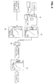
- FIG. 4 is a block diagram showing the contents of calculations or an arithmetic operation to obtain a valve opening of EGR control valve 21.
- a target EGR rate is calculated based on a torque and engine rotation speed by referring to a target EGR rate calculation map.
- the torque may be calculated based on a detected value of accelerator opening sensor 29, and engine rotation speed may be obtained by a detection value of crank angle sensor 26.
- EGR rate calculation map may be configured by allocating target EGR rates depending on respective operation areas or regions of internal combustion engine 1.
- a target EGR rate is transformed into a target opening of EGR control valve 21.
- EGR rate may be determinable unambiguously or directly by defining an opening degree of EGR control valve, irrespective an amount of air flow.
- an estimate of exhaust gas density correction map is consulted based on an estimate of exhaust gas temperature and a exhaust gas correction coefficient will be obtained.
- the exhaust gas estimate is made based on an engine rotation speed detected by crank angle sensor 26 and obtainable by using a map of intake air amounts prepared with respective engine rotation speed ranges.
- a reference valve opening is calculated by dividing an opening area of EGR control calculated in S2 by exhaust gas density correction coefficient obtained in S3.
- the reference valve opening area will be transformed into a valve opening degree of EGR control valve 21 and an actual valve opening degree of EGR control valve 21 will be adjusted or corrected accordingly. As the reference valve area increases, the opening degree of EGR control valve 21 also increases.
- the above mentioned reference valve opening will be subjected to a transient correction (depending on valve opening area correction value) to obtain a valve opening area in the transient state, and this transitional valve opening will be transformed into an opening degree of EGR control valve 21 to control EGR control valve to match the transformed valve opening degree.
- FIG. 5 is a block diagram showing the computation contents of the valve opening during a transient state.
- step S11 an estimate of intake air pressure at an EGR injection point is calculated based on an intake air amount detected by airflow meter 6 and by referring to an estimate intake air pressure calculation map.
- the intake air pressure may be calculated on the assumption that the pressure loss due to intake air system associated components, which are present upstream of this position, such as air cleaner 7 is represented by an orifice of constant diameter. When the intake air increases, the calculated intake air also increases in gauge.
- a first estimate of exhaust gas pressure at a position of EGR extract is obtained based on the detected intake air amount of airflow meter and referring to a first exhaust gas pressure calculation map.
- the exhaust gas pressure at the position of EGR extract may be calculated by an intake air amount on the presumption that the pressure loss created by an exhaust gas associated component such as an underfloor catalyst (not shown) or muffler (not shown) may be represented by an orifice of constant diameter.
- the first estimate of exhaust gas pressure does not reflect a delay of first order and/or loss time. As the intake air increases, the calculated value for first estimate of exhaust gas pressure also increases.
- step S13 a difference between the estimated intake air pressure calculated in S11 and the first estimate of exhaust gas pressure calculated in S12 is obtained to determine a pressure difference in a stable state, i.e., neglecting or ignoring the influences due to a first order delay or lag/waste time.
- a delay in pressure change in response to change in intake air amount may be considered due to different location of airflow meter 6 and the location in which an actual pressure loss takes place. More specifically, when estimating an exhaust gas pressure based on intake air amount, a gas transportation delay occurs from the position of airflow meter 6 to the above mentioned EGR extract position, the timing at which the exhaust gas pressure changes at the EGR extract position will be delayed accordingly. This response delay is treated in this embodiment as a first-order time constant, loss/waste time.
- a time constant for delay in pressure change (a first order delay) may be calculated. As the engine rotation speed increases, the calculated time constant becomes small.
- a lag or waste time may be obtained. More specifically, the lag or waste time is associated with a time during which a gas or intake air is enclosed or trapped into and subsequently expelled from a combustion chamber. As the engine rotation speed increases, the calculated lag or waste time will decrease.
- a second estimate of exhaust gas pressure may be calculated based upon the first estimate of exhaust gas pressure and applying the time constant obtained in S 14 as well as a waste time obtained in S 15 so as to the first-order time delay and waste time are taken into account.
- the estimated intake air pressure and the second estimate of exhaust gas pressure calculated in S16 are used to obtain a difference so that a pressure difference reflecting the first order delay and waste time, i.e., a pressure difference in a transient state, may be obtained. Also, based on the pressure difference in the transient state and the pressure difference neglecting the first order delay and waste time, a difference or rate of these two values are obtained to calculate a valve area correction value.
- the EGR rate decreases when the intake air amount increases, while the EGR rate increases in response to intake air amount decreasing.
- the intake air amount increases i.e ., when the pressure difference between the estimated air pressure and the second estimate of exhaust gas pressure is small relative to the pressure difference between the estimated intake air pressure and the first estimate of exhaust gas pressure, an EGR rate will be reduced due to a delay in increase in the exhaust gas pressure at the EGR extract position.
- the valve area correction value which is calculated in S17 may be determined to take a larger value to increase an EGR gas amount as the pressure difference which reflects both a first-order delay and waste time becomes smaller as compared to the pressure difference without taking the first-order delay and waste time into account.
- the valve area correction value will be smaller to decrease an EGR gas amount as the pressure difference which reflects both a first-order delay and waste time becomes larger as compared to the pressure difference ignoring the first-order delay and waste time considerations.
- a transient valve area will be determined by applying a transient correction on the above mentioned reference valve area. More specifically, by multiplying the above mentioned reference valve area and the valve area correction value calculated in S 17, the transient valve area will be obtained, which will be employed for adjustment of valve area to maintain the EGR rate stable during a transient operation.
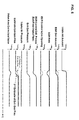
- FIG. 6 shows a timing chart explaining changes of various parameters over time during a transient operation.
- the exhaust gas pressure will change with a time delay of a timing at which an intake air amount changes.
- the difference pressure between the EGR extract position and EGR injection position increases with a time delay from the change in intake air amount.
- EGR amount will also be delayed from the change of intake air amount so that the EGR rate will be decreased as shown in bold line in FIG. 6 .
- EGR gas amount is required to increase the same change rate as that of intake air amount.
- the valve area of EGR control valve 21 will be increased in advance, as indicated in dotted line in FIG. 6 .
- the opening area of EGR control valve 21 may not be manipulated quickly enough. Therefore, in one or more embodiments of the present disclosure, the pressure difference between EGR extract position and EGR injection position will be estimated or predicted, and adjustment on an opening area of EGR control valve 21 will be performed, in advance.
- the estimates of exhaust gas pressure at the EGR extract position may be represented either by a first estimate of exhaust gas pressure, as indicated in a dashed line in FIG. 6 , which ignores or neglects the first-order delay and waste time, or by a second estimate of exhaust gas pressure, as indicated in a solid line in FIG. 6 , which takes both the first-order delay and waste time into consideration.
- EGR rate may be kept constant even at a constant value of valve opening area of EGR control valve 21, since the EGR amount changed in a broken line in FIG. 6 .
- valve area correction value will be calculated for adjustments of valve opening of EGR control valve 21 during transient periods.
- valve opening area of EGR control valve 21 is adjusted or corrected based on an estimate of intake air pressure in a position in which EGR passage is connected to intake passage 2 and a second estimate of exhaust gas pressure which is determined by taking a response delay into account in a position in which the EGR passage is connected to exhaust passage (EGR extract position). Therefore, even in a transient state of operation, EGR rate will be controlled with a sufficient accuracy, i.e., kept constant.
- EGR control valve 21 may be controlled to maintain a constant EGR rate without relying on use of a sensor to actually detect pressures prior to and after EGR valve 21.
- an influence of exhaust gas temperature on exhaust gas pressure is considered, and the valve opening area is further corrected depending on the exhaust gas temperature.
Landscapes
- Engineering & Computer Science (AREA)
- Chemical & Material Sciences (AREA)
- Combustion & Propulsion (AREA)
- Mechanical Engineering (AREA)
- General Engineering & Computer Science (AREA)
- Exhaust-Gas Circulating Devices (AREA)
- Output Control And Ontrol Of Special Type Engine (AREA)
Applications Claiming Priority (1)
| Application Number | Priority Date | Filing Date | Title |
|---|---|---|---|
| JP2011125935A JP5929015B2 (ja) | 2011-06-06 | 2011-06-06 | 内燃機関の排気還流装置 |
Publications (3)
| Publication Number | Publication Date |
|---|---|
| EP2532867A2 true EP2532867A2 (de) | 2012-12-12 |
| EP2532867A3 EP2532867A3 (de) | 2018-02-07 |
| EP2532867B1 EP2532867B1 (de) | 2020-03-25 |
Family
ID=46229246
Family Applications (1)
| Application Number | Title | Priority Date | Filing Date |
|---|---|---|---|
| EP12170322.7A Active EP2532867B1 (de) | 2011-06-06 | 2012-05-31 | Abgasrückführungssystem für eine brennkraftmaschine |
Country Status (4)
| Country | Link |
|---|---|
| US (1) | US9091223B2 (de) |
| EP (1) | EP2532867B1 (de) |
| JP (1) | JP5929015B2 (de) |
| CN (1) | CN102817748B (de) |
Cited By (5)
| Publication number | Priority date | Publication date | Assignee | Title |
|---|---|---|---|---|
| CN103334841A (zh) * | 2013-07-09 | 2013-10-02 | 潍柴动力股份有限公司 | 一种egr死区控制方法及系统 |
| WO2014161558A1 (en) * | 2013-04-05 | 2014-10-09 | Volvo Truck Corporation | Method and apparatus for controlling an engine with egr and a turbocharger |
| CN106662029A (zh) * | 2014-08-29 | 2017-05-10 | 日立汽车系统株式会社 | 内燃机的装置 |
| EP3067546A4 (de) * | 2013-10-09 | 2017-05-24 | Yanmar Co., Ltd. | Motor |
| EP3511558A4 (de) * | 2016-09-07 | 2019-10-02 | Nissan Motor Co., Ltd. | Motorsteuerungsverfahren und steuerungsvorrichtung |
Families Citing this family (27)
| Publication number | Priority date | Publication date | Assignee | Title |
|---|---|---|---|---|
| US9819038B2 (en) | 2011-03-31 | 2017-11-14 | General Electric Company | Fuel cell reforming system with carbon dioxide removal |
| FR2981408B1 (fr) * | 2011-10-12 | 2013-10-18 | IFP Energies Nouvelles | Procede de commande d'une vanne integree dans un circuit de recirculation des gaz d'echappement d'un moteur |
| JP5994430B2 (ja) * | 2012-06-28 | 2016-09-21 | いすゞ自動車株式会社 | 内燃機関、それを搭載した車両、及びその制御方法 |
| EP2876291B1 (de) * | 2012-07-18 | 2018-08-22 | Nissan Motor Co., Ltd | Verbrennungsmotor |
| DE102012024927A1 (de) * | 2012-12-19 | 2014-06-26 | Volkswagen Aktiengesellschaft | Verfahren zum Betreiben einer Brennkraftmaschine |
| US9021805B2 (en) * | 2013-07-31 | 2015-05-05 | Ford Global Technologies, Llc | Exhaust gas recirculation control |
| JP6049577B2 (ja) * | 2013-09-16 | 2016-12-21 | 愛三工業株式会社 | 過給機付きエンジンの排気還流装置 |
| FR3011073B1 (fr) * | 2013-09-26 | 2015-10-16 | Valeo Sys Controle Moteur Sas | Procede de determination du taux d’egr dans un moteur thermique |
| DE102013224766A1 (de) * | 2013-12-03 | 2015-06-03 | Robert Bosch Gmbh | Verfahren und Messanordnung zur Bestimmung eines Frischluftmassenstromes |
| JP6226775B2 (ja) * | 2014-02-26 | 2017-11-08 | ヤンマー株式会社 | エンジン装置 |
| WO2016038591A1 (en) * | 2014-09-12 | 2016-03-17 | Bombardier Recreational Products Inc. | Method for controlling a forced induction engine |
| WO2017048233A1 (en) * | 2015-09-15 | 2017-03-23 | Cummins Inc. | Air-handling control system with asymmetric turbocharger |
| FR3044046B1 (fr) * | 2015-11-25 | 2019-09-13 | Continental Automotive France | Procede de controle d'un moteur thermique |
| KR20170139926A (ko) * | 2016-06-10 | 2017-12-20 | 현대자동차주식회사 | 배기 가스 재순환 장치를 구비한 엔진 시스템 및 제어 방법 |
| KR101896327B1 (ko) * | 2016-09-13 | 2018-09-07 | 현대자동차 주식회사 | 엔진 시스템 및 이를 이용한 제어 방법 |
| CN107288765A (zh) * | 2017-08-22 | 2017-10-24 | 吉林大学 | 基于进气流量计信息的可变增压发动机egr率反馈控制方法 |
| CN107795412A (zh) * | 2017-11-02 | 2018-03-13 | 广西玉柴机器股份有限公司 | 发动机的低压冷端egr系统 |
| JP6930902B2 (ja) * | 2017-11-10 | 2021-09-01 | 日野自動車株式会社 | バルブ制御装置 |
| JP6844556B2 (ja) * | 2018-02-09 | 2021-03-17 | トヨタ自動車株式会社 | 内燃機関の排気浄化装置 |
| WO2020001780A1 (en) * | 2018-06-29 | 2020-01-02 | Volvo Truck Corporation | An internal combustion engine |
| CN113685280B (zh) * | 2020-05-19 | 2022-11-25 | 广州汽车集团股份有限公司 | 一种egr率的控制方法及装置 |
| CN113833586B (zh) * | 2020-06-24 | 2022-12-20 | 广州汽车集团股份有限公司 | 废气再循环系统及其方法、汽车 |
| CN112182744B (zh) * | 2020-09-10 | 2022-11-04 | 东风汽车集团有限公司 | 一种egr率预测方法、装置、设备和介质 |
| CN112324581B (zh) * | 2020-11-04 | 2023-05-23 | 潍柴动力股份有限公司 | 一种egr瞬态控制方法及装置、电子设备 |
| US20230212993A1 (en) * | 2022-01-06 | 2023-07-06 | Transportation Ip Holdings, Llc | Sensor system and method |
| CN115013172B (zh) * | 2022-06-15 | 2023-06-27 | 东风汽车集团股份有限公司 | 一种egr阀入口压力信号异常处理方法 |
| CN121729557A (zh) * | 2023-08-30 | 2026-03-24 | 日产自动车株式会社 | 排气回流装置的控制方法及装置 |
Citations (1)
| Publication number | Priority date | Publication date | Assignee | Title |
|---|---|---|---|---|
| US6868329B2 (en) | 2002-10-30 | 2005-03-15 | Komatsu Ltd. | Control method of EGR system of engine |
Family Cites Families (26)
| Publication number | Priority date | Publication date | Assignee | Title |
|---|---|---|---|---|
| KR100462458B1 (ko) | 1996-03-15 | 2005-05-24 | 지멘스 악티엔게젤샤프트 | 외부배기가스를재순환하는내연기관의실린더로유입되는맑은공기의질량을모델을이용하여결정하는방법 |
| JP3358449B2 (ja) * | 1996-07-09 | 2002-12-16 | 日産自動車株式会社 | 内燃機関の排気系圧力推定装置 |
| GB2313927B (en) * | 1996-06-03 | 1999-06-23 | Nissan Motor | EGR control apparatus for internal combustion engine |
| JP3551717B2 (ja) | 1997-08-08 | 2004-08-11 | 日産自動車株式会社 | エンジンのegr制御装置 |
| JP3826592B2 (ja) | 1998-12-08 | 2006-09-27 | マツダ株式会社 | ターボ過給機付エンジンの制御装置 |
| JP3680639B2 (ja) | 1999-06-15 | 2005-08-10 | 日産自動車株式会社 | エンジンの制御装置 |
| US6658364B2 (en) * | 2001-01-12 | 2003-12-02 | Delphi Technologies, Inc. | Method of estimating gas pressure in an engine exhaust manifold |
| US6732522B2 (en) * | 2002-04-08 | 2004-05-11 | Cummins, Inc. | System for estimating engine exhaust pressure |
| JP4534514B2 (ja) | 2004-02-18 | 2010-09-01 | 株式会社デンソー | ディーゼル機関の制御装置 |
| JP4339321B2 (ja) * | 2006-01-20 | 2009-10-07 | 本田技研工業株式会社 | 内燃機関の制御装置 |
| JP4577348B2 (ja) * | 2007-10-24 | 2010-11-10 | 株式会社デンソー | 内燃機関制御装置及び内燃機関制御システム |
| DE602008001659D1 (de) * | 2008-01-29 | 2010-08-12 | Honda Motor Co Ltd | Steuersystem für einen Verbrennungsmotor |
| DE602008001660D1 (de) * | 2008-01-29 | 2010-08-12 | Honda Motor Co Ltd | Steuersystem für einen Verbrennungsmotor |
| JP2009185732A (ja) | 2008-02-07 | 2009-08-20 | Toyota Motor Corp | 内燃機関の制御装置 |
| JP2010059916A (ja) | 2008-09-05 | 2010-03-18 | Yanmar Co Ltd | エンジン |
| JP2010116894A (ja) | 2008-11-14 | 2010-05-27 | Toyota Motor Corp | 内燃機関の制御装置 |
| JP2010242617A (ja) | 2009-04-06 | 2010-10-28 | Toyota Motor Corp | 内燃機関の異常検出システム |
| EP2495419B1 (de) * | 2009-10-30 | 2014-12-24 | Toyota Jidosha Kabushiki Kaisha | Steuerungssystem für einen verbrennungsmotor |
| JP5143170B2 (ja) * | 2010-03-17 | 2013-02-13 | 日立オートモティブシステムズ株式会社 | 内燃機関の制御方法 |
| DE102010050161A1 (de) * | 2010-10-30 | 2012-05-03 | Volkswagen Ag | Verfahren zur Bestimmung eines Drucks am Ausgang einer Abgasanlage |
| US8627660B2 (en) * | 2010-12-02 | 2014-01-14 | Toyota Jidosha Kabushiki Kaisha | Control device for internal combustion engine with supercharger |
| DE102011006756B4 (de) * | 2011-04-05 | 2021-06-10 | Robert Bosch Gmbh | Antriebssystem für ein Kraftfahrzeug |
| DE102012204756A1 (de) * | 2012-03-26 | 2013-09-26 | Robert Bosch Gmbh | Verfahren und Vorrichtung zur Fehlerüberwachung in einer Abgas-Rückführung |
| US9279396B2 (en) * | 2012-05-17 | 2016-03-08 | Ford Global Technologies, Llc | Boost air management for improved engine performance |
| US9528429B2 (en) * | 2012-05-17 | 2016-12-27 | Ford Global Technologies, Llc | Boost reservoir EGR control |
| DE102012211900B4 (de) * | 2012-07-09 | 2022-03-24 | Robert Bosch Gmbh | Verfahren zur Korrektur eines Offsets für eine mit einem in einem Luftkanal angeordneten Druckdifferenzsensor gemessene Druckdifferenz |
-
2011
- 2011-06-06 JP JP2011125935A patent/JP5929015B2/ja not_active Expired - Fee Related
-
2012
- 2012-05-16 US US13/472,952 patent/US9091223B2/en active Active
- 2012-05-30 CN CN201210173180.4A patent/CN102817748B/zh active Active
- 2012-05-31 EP EP12170322.7A patent/EP2532867B1/de active Active
Patent Citations (1)
| Publication number | Priority date | Publication date | Assignee | Title |
|---|---|---|---|---|
| US6868329B2 (en) | 2002-10-30 | 2005-03-15 | Komatsu Ltd. | Control method of EGR system of engine |
Cited By (10)
| Publication number | Priority date | Publication date | Assignee | Title |
|---|---|---|---|---|
| WO2014161558A1 (en) * | 2013-04-05 | 2014-10-09 | Volvo Truck Corporation | Method and apparatus for controlling an engine with egr and a turbocharger |
| US10859014B2 (en) | 2013-04-05 | 2020-12-08 | Volvo Truck Corporation | Method and apparatus for controlling an engine with EGR and a turbocharger |
| CN103334841A (zh) * | 2013-07-09 | 2013-10-02 | 潍柴动力股份有限公司 | 一种egr死区控制方法及系统 |
| CN103334841B (zh) * | 2013-07-09 | 2015-09-09 | 潍柴动力股份有限公司 | 一种egr死区控制方法及系统 |
| EP3067546A4 (de) * | 2013-10-09 | 2017-05-24 | Yanmar Co., Ltd. | Motor |
| CN106662029A (zh) * | 2014-08-29 | 2017-05-10 | 日立汽车系统株式会社 | 内燃机的装置 |
| EP3187719A4 (de) * | 2014-08-29 | 2018-06-13 | Hitachi Automotive Systems, Ltd. | Vorrichtung für einen verbrennungsmotor |
| CN106662029B (zh) * | 2014-08-29 | 2020-06-05 | 日立汽车系统株式会社 | 内燃机的装置 |
| EP3187719B1 (de) * | 2014-08-29 | 2022-12-07 | Hitachi Astemo, Ltd. | Vorrichtung für einen verbrennungsmotor |
| EP3511558A4 (de) * | 2016-09-07 | 2019-10-02 | Nissan Motor Co., Ltd. | Motorsteuerungsverfahren und steuerungsvorrichtung |
Also Published As
| Publication number | Publication date |
|---|---|
| EP2532867A3 (de) | 2018-02-07 |
| CN102817748B (zh) | 2014-10-29 |
| CN102817748A (zh) | 2012-12-12 |
| JP5929015B2 (ja) | 2016-06-01 |
| JP2012251509A (ja) | 2012-12-20 |
| US20120304640A1 (en) | 2012-12-06 |
| EP2532867B1 (de) | 2020-03-25 |
| US9091223B2 (en) | 2015-07-28 |
Similar Documents
| Publication | Publication Date | Title |
|---|---|---|
| EP2532867B1 (de) | Abgasrückführungssystem für eine brennkraftmaschine | |
| EP2803842B1 (de) | Steuerungsvorrichtung für einen verbrennungsmotor | |
| US7137247B2 (en) | Regeneration apparatus and method for particulate filter applicable to engine exhaust gas purifying device | |
| JP4595701B2 (ja) | 電動機付き過給機を有する内燃機関の制御装置 | |
| US7047740B2 (en) | Boost pressure estimation apparatus for internal combustion engine with supercharger | |
| EP2518291B1 (de) | Steuervorrichtung für einen Verbrennungsmotor | |
| EP3187719B1 (de) | Vorrichtung für einen verbrennungsmotor | |
| US20160084176A1 (en) | Control device and control method for an internal combustion engine with a supercharger | |
| JP5865942B2 (ja) | 内燃機関のシリンダ吸入空気量推定装置および推定方法 | |
| US20090158713A1 (en) | Exhaust Gas Purification System for Internal Combustion Engine | |
| EP2565430B1 (de) | Steuervorrichtung für einen verbrennungsmotor | |
| JP6795933B2 (ja) | ターボ回転数制御装置およびターボ回転数制御方法 | |
| JP5116870B1 (ja) | 内燃機関の大気圧推定制御装置および大気圧推定方法 | |
| JP6127906B2 (ja) | 内燃機関の制御装置 | |
| JP5111534B2 (ja) | 内燃機関のegr制御装置 | |
| EP2390490B1 (de) | Steuerungsvorrichtung für einen verbrennungsmotor | |
| JP2016200034A (ja) | 内燃機関の制御装置 | |
| JP2017110549A (ja) | 内燃機関の制御装置 | |
| EP3075991B1 (de) | Steuerungsvorrichtung für verbrennungsmotor | |
| JP2023144256A (ja) | 内燃機関の最大充填効率推定方法および装置 | |
| JP2012107525A (ja) | 内燃機関の還流制御装置 |
Legal Events
| Date | Code | Title | Description |
|---|---|---|---|
| PUAI | Public reference made under article 153(3) epc to a published international application that has entered the european phase |
Free format text: ORIGINAL CODE: 0009012 |
|
| AK | Designated contracting states |
Kind code of ref document: A2 Designated state(s): AL AT BE BG CH CY CZ DE DK EE ES FI FR GB GR HR HU IE IS IT LI LT LU LV MC MK MT NL NO PL PT RO RS SE SI SK SM TR |
|
| AX | Request for extension of the european patent |
Extension state: BA ME |
|
| PUAL | Search report despatched |
Free format text: ORIGINAL CODE: 0009013 |
|
| AK | Designated contracting states |
Kind code of ref document: A3 Designated state(s): AL AT BE BG CH CY CZ DE DK EE ES FI FR GB GR HR HU IE IS IT LI LT LU LV MC MK MT NL NO PL PT RO RS SE SI SK SM TR |
|
| AX | Request for extension of the european patent |
Extension state: BA ME |
|
| RIC1 | Information provided on ipc code assigned before grant |
Ipc: F02D 41/00 20060101AFI20180102BHEP Ipc: F02M 25/07 00000000ALI20180102BHEP |
|
| STAA | Information on the status of an ep patent application or granted ep patent |
Free format text: STATUS: REQUEST FOR EXAMINATION WAS MADE |
|
| 17P | Request for examination filed |
Effective date: 20180807 |
|
| RBV | Designated contracting states (corrected) |
Designated state(s): AL AT BE BG CH CY CZ DE DK EE ES FI FR GB GR HR HU IE IS IT LI LT LU LV MC MK MT NL NO PL PT RO RS SE SI SK SM TR |
|
| RIC1 | Information provided on ipc code assigned before grant |
Ipc: F02D 41/00 20060101AFI20180102BHEP Ipc: F02M 25/07 20181130ALI20180102BHEP |
|
| RIC1 | Information provided on ipc code assigned before grant |
Ipc: F02D 41/00 20060101AFI20180102BHEP Ipc: F02M 25/07 20060101ALI20180102BHEP |
|
| STAA | Information on the status of an ep patent application or granted ep patent |
Free format text: STATUS: EXAMINATION IS IN PROGRESS |
|
| 17Q | First examination report despatched |
Effective date: 20190401 |
|
| RIC1 | Information provided on ipc code assigned before grant |
Ipc: F02D 41/00 20060101AFI20191002BHEP |
|
| RIC1 | Information provided on ipc code assigned before grant |
Ipc: F02D 21/08 20060101ALI20191009BHEP Ipc: F02D 41/00 20060101AFI20191009BHEP Ipc: F02D 41/18 20060101ALI20191009BHEP Ipc: F02D 41/14 20060101ALI20191009BHEP |
|
| GRAP | Despatch of communication of intention to grant a patent |
Free format text: ORIGINAL CODE: EPIDOSNIGR1 |
|
| STAA | Information on the status of an ep patent application or granted ep patent |
Free format text: STATUS: GRANT OF PATENT IS INTENDED |
|
| INTG | Intention to grant announced |
Effective date: 20191118 |
|
| GRAS | Grant fee paid |
Free format text: ORIGINAL CODE: EPIDOSNIGR3 |
|
| GRAJ | Information related to disapproval of communication of intention to grant by the applicant or resumption of examination proceedings by the epo deleted |
Free format text: ORIGINAL CODE: EPIDOSDIGR1 |
|
| GRAL | Information related to payment of fee for publishing/printing deleted |
Free format text: ORIGINAL CODE: EPIDOSDIGR3 |
|
| STAA | Information on the status of an ep patent application or granted ep patent |
Free format text: STATUS: EXAMINATION IS IN PROGRESS |
|
| INTC | Intention to grant announced (deleted) | ||
| GRAR | Information related to intention to grant a patent recorded |
Free format text: ORIGINAL CODE: EPIDOSNIGR71 |
|
| STAA | Information on the status of an ep patent application or granted ep patent |
Free format text: STATUS: GRANT OF PATENT IS INTENDED |
|
| GRAA | (expected) grant |
Free format text: ORIGINAL CODE: 0009210 |
|
| STAA | Information on the status of an ep patent application or granted ep patent |
Free format text: STATUS: THE PATENT HAS BEEN GRANTED |
|
| AK | Designated contracting states |
Kind code of ref document: B1 Designated state(s): AL AT BE BG CH CY CZ DE DK EE ES FI FR GB GR HR HU IE IS IT LI LT LU LV MC MK MT NL NO PL PT RO RS SE SI SK SM TR |
|
| INTG | Intention to grant announced |
Effective date: 20200214 |
|
| REG | Reference to a national code |
Ref country code: GB Ref legal event code: FG4D |
|
| REG | Reference to a national code |
Ref country code: DE Ref legal event code: R096 Ref document number: 602012068684 Country of ref document: DE |
|
| REG | Reference to a national code |
Ref country code: AT Ref legal event code: REF Ref document number: 1248821 Country of ref document: AT Kind code of ref document: T Effective date: 20200415 Ref country code: IE Ref legal event code: FG4D |
|
| PG25 | Lapsed in a contracting state [announced via postgrant information from national office to epo] |
Ref country code: FI Free format text: LAPSE BECAUSE OF FAILURE TO SUBMIT A TRANSLATION OF THE DESCRIPTION OR TO PAY THE FEE WITHIN THE PRESCRIBED TIME-LIMIT Effective date: 20200325 Ref country code: NO Free format text: LAPSE BECAUSE OF FAILURE TO SUBMIT A TRANSLATION OF THE DESCRIPTION OR TO PAY THE FEE WITHIN THE PRESCRIBED TIME-LIMIT Effective date: 20200625 Ref country code: RS Free format text: LAPSE BECAUSE OF FAILURE TO SUBMIT A TRANSLATION OF THE DESCRIPTION OR TO PAY THE FEE WITHIN THE PRESCRIBED TIME-LIMIT Effective date: 20200325 |
|
| PG25 | Lapsed in a contracting state [announced via postgrant information from national office to epo] |
Ref country code: BG Free format text: LAPSE BECAUSE OF FAILURE TO SUBMIT A TRANSLATION OF THE DESCRIPTION OR TO PAY THE FEE WITHIN THE PRESCRIBED TIME-LIMIT Effective date: 20200625 Ref country code: HR Free format text: LAPSE BECAUSE OF FAILURE TO SUBMIT A TRANSLATION OF THE DESCRIPTION OR TO PAY THE FEE WITHIN THE PRESCRIBED TIME-LIMIT Effective date: 20200325 Ref country code: GR Free format text: LAPSE BECAUSE OF FAILURE TO SUBMIT A TRANSLATION OF THE DESCRIPTION OR TO PAY THE FEE WITHIN THE PRESCRIBED TIME-LIMIT Effective date: 20200626 Ref country code: LV Free format text: LAPSE BECAUSE OF FAILURE TO SUBMIT A TRANSLATION OF THE DESCRIPTION OR TO PAY THE FEE WITHIN THE PRESCRIBED TIME-LIMIT Effective date: 20200325 Ref country code: SE Free format text: LAPSE BECAUSE OF FAILURE TO SUBMIT A TRANSLATION OF THE DESCRIPTION OR TO PAY THE FEE WITHIN THE PRESCRIBED TIME-LIMIT Effective date: 20200325 |
|
| REG | Reference to a national code |
Ref country code: NL Ref legal event code: MP Effective date: 20200325 |
|
| REG | Reference to a national code |
Ref country code: LT Ref legal event code: MG4D |
|
| PG25 | Lapsed in a contracting state [announced via postgrant information from national office to epo] |
Ref country code: NL Free format text: LAPSE BECAUSE OF FAILURE TO SUBMIT A TRANSLATION OF THE DESCRIPTION OR TO PAY THE FEE WITHIN THE PRESCRIBED TIME-LIMIT Effective date: 20200325 |
|
| PG25 | Lapsed in a contracting state [announced via postgrant information from national office to epo] |
Ref country code: LT Free format text: LAPSE BECAUSE OF FAILURE TO SUBMIT A TRANSLATION OF THE DESCRIPTION OR TO PAY THE FEE WITHIN THE PRESCRIBED TIME-LIMIT Effective date: 20200325 Ref country code: CZ Free format text: LAPSE BECAUSE OF FAILURE TO SUBMIT A TRANSLATION OF THE DESCRIPTION OR TO PAY THE FEE WITHIN THE PRESCRIBED TIME-LIMIT Effective date: 20200325 Ref country code: PT Free format text: LAPSE BECAUSE OF FAILURE TO SUBMIT A TRANSLATION OF THE DESCRIPTION OR TO PAY THE FEE WITHIN THE PRESCRIBED TIME-LIMIT Effective date: 20200818 Ref country code: IS Free format text: LAPSE BECAUSE OF FAILURE TO SUBMIT A TRANSLATION OF THE DESCRIPTION OR TO PAY THE FEE WITHIN THE PRESCRIBED TIME-LIMIT Effective date: 20200725 Ref country code: RO Free format text: LAPSE BECAUSE OF FAILURE TO SUBMIT A TRANSLATION OF THE DESCRIPTION OR TO PAY THE FEE WITHIN THE PRESCRIBED TIME-LIMIT Effective date: 20200325 Ref country code: SK Free format text: LAPSE BECAUSE OF FAILURE TO SUBMIT A TRANSLATION OF THE DESCRIPTION OR TO PAY THE FEE WITHIN THE PRESCRIBED TIME-LIMIT Effective date: 20200325 Ref country code: SM Free format text: LAPSE BECAUSE OF FAILURE TO SUBMIT A TRANSLATION OF THE DESCRIPTION OR TO PAY THE FEE WITHIN THE PRESCRIBED TIME-LIMIT Effective date: 20200325 Ref country code: EE Free format text: LAPSE BECAUSE OF FAILURE TO SUBMIT A TRANSLATION OF THE DESCRIPTION OR TO PAY THE FEE WITHIN THE PRESCRIBED TIME-LIMIT Effective date: 20200325 |
|
| REG | Reference to a national code |
Ref country code: AT Ref legal event code: MK05 Ref document number: 1248821 Country of ref document: AT Kind code of ref document: T Effective date: 20200325 |
|
| REG | Reference to a national code |
Ref country code: DE Ref legal event code: R097 Ref document number: 602012068684 Country of ref document: DE |
|
| PG25 | Lapsed in a contracting state [announced via postgrant information from national office to epo] |
Ref country code: LI Free format text: LAPSE BECAUSE OF NON-PAYMENT OF DUE FEES Effective date: 20200531 Ref country code: MC Free format text: LAPSE BECAUSE OF FAILURE TO SUBMIT A TRANSLATION OF THE DESCRIPTION OR TO PAY THE FEE WITHIN THE PRESCRIBED TIME-LIMIT Effective date: 20200325 Ref country code: ES Free format text: LAPSE BECAUSE OF FAILURE TO SUBMIT A TRANSLATION OF THE DESCRIPTION OR TO PAY THE FEE WITHIN THE PRESCRIBED TIME-LIMIT Effective date: 20200325 Ref country code: CH Free format text: LAPSE BECAUSE OF NON-PAYMENT OF DUE FEES Effective date: 20200531 Ref country code: AT Free format text: LAPSE BECAUSE OF FAILURE TO SUBMIT A TRANSLATION OF THE DESCRIPTION OR TO PAY THE FEE WITHIN THE PRESCRIBED TIME-LIMIT Effective date: 20200325 Ref country code: DK Free format text: LAPSE BECAUSE OF FAILURE TO SUBMIT A TRANSLATION OF THE DESCRIPTION OR TO PAY THE FEE WITHIN THE PRESCRIBED TIME-LIMIT Effective date: 20200325 Ref country code: IT Free format text: LAPSE BECAUSE OF FAILURE TO SUBMIT A TRANSLATION OF THE DESCRIPTION OR TO PAY THE FEE WITHIN THE PRESCRIBED TIME-LIMIT Effective date: 20200325 |
|
| PLBE | No opposition filed within time limit |
Free format text: ORIGINAL CODE: 0009261 |
|
| STAA | Information on the status of an ep patent application or granted ep patent |
Free format text: STATUS: NO OPPOSITION FILED WITHIN TIME LIMIT |
|
| PG25 | Lapsed in a contracting state [announced via postgrant information from national office to epo] |
Ref country code: PL Free format text: LAPSE BECAUSE OF FAILURE TO SUBMIT A TRANSLATION OF THE DESCRIPTION OR TO PAY THE FEE WITHIN THE PRESCRIBED TIME-LIMIT Effective date: 20200325 |
|
| 26N | No opposition filed |
Effective date: 20210112 |
|
| REG | Reference to a national code |
Ref country code: BE Ref legal event code: MM Effective date: 20200531 |
|
| PG25 | Lapsed in a contracting state [announced via postgrant information from national office to epo] |
Ref country code: LU Free format text: LAPSE BECAUSE OF NON-PAYMENT OF DUE FEES Effective date: 20200531 |
|
| PG25 | Lapsed in a contracting state [announced via postgrant information from national office to epo] |
Ref country code: IE Free format text: LAPSE BECAUSE OF NON-PAYMENT OF DUE FEES Effective date: 20200531 |
|
| PG25 | Lapsed in a contracting state [announced via postgrant information from national office to epo] |
Ref country code: BE Free format text: LAPSE BECAUSE OF NON-PAYMENT OF DUE FEES Effective date: 20200531 Ref country code: SI Free format text: LAPSE BECAUSE OF FAILURE TO SUBMIT A TRANSLATION OF THE DESCRIPTION OR TO PAY THE FEE WITHIN THE PRESCRIBED TIME-LIMIT Effective date: 20200325 |
|
| PG25 | Lapsed in a contracting state [announced via postgrant information from national office to epo] |
Ref country code: TR Free format text: LAPSE BECAUSE OF FAILURE TO SUBMIT A TRANSLATION OF THE DESCRIPTION OR TO PAY THE FEE WITHIN THE PRESCRIBED TIME-LIMIT Effective date: 20200325 Ref country code: MT Free format text: LAPSE BECAUSE OF FAILURE TO SUBMIT A TRANSLATION OF THE DESCRIPTION OR TO PAY THE FEE WITHIN THE PRESCRIBED TIME-LIMIT Effective date: 20200325 Ref country code: CY Free format text: LAPSE BECAUSE OF FAILURE TO SUBMIT A TRANSLATION OF THE DESCRIPTION OR TO PAY THE FEE WITHIN THE PRESCRIBED TIME-LIMIT Effective date: 20200325 |
|
| PG25 | Lapsed in a contracting state [announced via postgrant information from national office to epo] |
Ref country code: MK Free format text: LAPSE BECAUSE OF FAILURE TO SUBMIT A TRANSLATION OF THE DESCRIPTION OR TO PAY THE FEE WITHIN THE PRESCRIBED TIME-LIMIT Effective date: 20200325 Ref country code: AL Free format text: LAPSE BECAUSE OF FAILURE TO SUBMIT A TRANSLATION OF THE DESCRIPTION OR TO PAY THE FEE WITHIN THE PRESCRIBED TIME-LIMIT Effective date: 20200325 |
|
| PGFP | Annual fee paid to national office [announced via postgrant information from national office to epo] |
Ref country code: DE Payment date: 20250423 Year of fee payment: 14 |
|
| PGFP | Annual fee paid to national office [announced via postgrant information from national office to epo] |
Ref country code: GB Payment date: 20250423 Year of fee payment: 14 |
|
| PGFP | Annual fee paid to national office [announced via postgrant information from national office to epo] |
Ref country code: FR Payment date: 20250423 Year of fee payment: 14 |