EP2532877A1 - Soupape d'injection de carburant pour moteurs à combustion interne - Google Patents
Soupape d'injection de carburant pour moteurs à combustion interne Download PDFInfo
- Publication number
- EP2532877A1 EP2532877A1 EP20120169087 EP12169087A EP2532877A1 EP 2532877 A1 EP2532877 A1 EP 2532877A1 EP 20120169087 EP20120169087 EP 20120169087 EP 12169087 A EP12169087 A EP 12169087A EP 2532877 A1 EP2532877 A1 EP 2532877A1
- Authority
- EP
- European Patent Office
- Prior art keywords
- fuel injection
- clamping nut
- injection valve
- holding body
- valve according
- Prior art date
- Legal status (The legal status is an assumption and is not a legal conclusion. Google has not performed a legal analysis and makes no representation as to the accuracy of the status listed.)
- Granted
Links
Images

Classifications
-
- F—MECHANICAL ENGINEERING; LIGHTING; HEATING; WEAPONS; BLASTING
- F02—COMBUSTION ENGINES; HOT-GAS OR COMBUSTION-PRODUCT ENGINE PLANTS
- F02M—SUPPLYING COMBUSTION ENGINES IN GENERAL WITH COMBUSTIBLE MIXTURES OR CONSTITUENTS THEREOF
- F02M61/00—Fuel-injectors not provided for in groups F02M39/00 - F02M57/00 or F02M67/00
- F02M61/16—Details not provided for in, or of interest apart from, the apparatus of groups F02M61/02 - F02M61/14
- F02M61/168—Assembling; Disassembling; Manufacturing; Adjusting
-
- F—MECHANICAL ENGINEERING; LIGHTING; HEATING; WEAPONS; BLASTING
- F02—COMBUSTION ENGINES; HOT-GAS OR COMBUSTION-PRODUCT ENGINE PLANTS
- F02M—SUPPLYING COMBUSTION ENGINES IN GENERAL WITH COMBUSTIBLE MIXTURES OR CONSTITUENTS THEREOF
- F02M2200/00—Details of fuel-injection apparatus, not otherwise provided for
- F02M2200/80—Fuel injection apparatus manufacture, repair or assembly
- F02M2200/803—Fuel injection apparatus manufacture, repair or assembly using clamp elements and fastening means; e.g. bolts or screws
-
- F—MECHANICAL ENGINEERING; LIGHTING; HEATING; WEAPONS; BLASTING
- F02—COMBUSTION ENGINES; HOT-GAS OR COMBUSTION-PRODUCT ENGINE PLANTS
- F02M—SUPPLYING COMBUSTION ENGINES IN GENERAL WITH COMBUSTIBLE MIXTURES OR CONSTITUENTS THEREOF
- F02M2200/00—Details of fuel-injection apparatus, not otherwise provided for
- F02M2200/80—Fuel injection apparatus manufacture, repair or assembly
- F02M2200/8076—Fuel injection apparatus manufacture, repair or assembly involving threaded members
Definitions
- the invention relates to a fuel injection valve for internal combustion engines according to the preamble of claim 1.
- Such a fuel injection valve is out of DE 10 2008 001 330 A1 the applicant known. It essentially comprises, on the side facing the combustion chamber of the internal combustion engine, a nozzle body accommodated in a housing, in which a nozzle needle is moved up and down.
- the nozzle needle is at least indirectly axially braced together with the nozzle body by means of a clamping nut against a holding body arranged in the housing.
- the clamping nut has an internal thread as part of a threaded connection, which cooperates with a corresponding external thread on the holding body and in particular also forms a seal of the housing arranged in the region of the nozzle body fuel, which is meant when operating fuel injection valve under relatively high pressure, here a pressure of more than 1500bar, stands.
- the present invention seeks to further develop a fuel injection valve for internal combustion engines according to the preamble of claim 1 such that the threaded connection, which connects the clamping nut with the holding body and a seal of the housing after forms on the outside, so educate, that it is particularly dense, especially at relatively high fuel pressures.
- the invention is based on the idea of designing the threaded connection in such a way that at least two toothing regions with different thread dimensions are present which follow one another axially in the longitudinal direction of the housing. This makes it possible to optimize the respective toothed areas with regard to their specific properties or tasks. In particular, this makes it possible, for example, optimally form a first toothed area with respect to its tightness, while a second toothed area is optimized with respect to the relatively simple mounting of the clamping nut.
- a thread-free intermediate section is formed between the two toothed regions.
- This unthreaded intermediate section makes it possible, in particular, to manufacture the two toothing regions on the clamping nut or on the holding body in a relatively simple manner.
- the axial length of the unthreaded intermediate region corresponds to the axial length of a first toothed region on the clamping nut, which is arranged on the side of the clamping nut facing the holding body.
- the second toothed region on the side of the clamping nut facing the nozzle body have the smaller thread diameter and a double number of teeth than the first toothed region.
- the wall thickness of the clamping nut in the second toothed region is greater than in the first toothed region. Due to the increased wall thickness of the clamping nut, the occurring compressive stresses can be absorbed particularly well, or a widening of the clamping nut due to the hydraulic pressure compared to the prior art is reduced, which increases the tightness of the second toothed region.
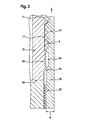
- Fig. 1 is a section of a fuel injection valve 100 according to the invention shown, as it is used for injecting fuel in a combustion chamber of an internal combustion engine, not shown, in particular a self-igniting internal combustion engine.
- the fuel injection valve 100 is part of a so-called common-rail injection system, in which each cylinder of the internal combustion engine, a separate, supplied by a common rail with fuel fuel injection valve 100 is assigned.
- the injection pressure of the fuel injection valve 100 is preferably more than 1500 bar.
- the fuel injection valve 100 has a housing 10, which is shown only in regions, in which, inter alia, an injection valve member (not shown), in particular in the form of a nozzle needle, is arranged to be movable up and down.
- a nozzle body 11 is arranged, which simultaneously forms the combustion chamber of the internal combustion engine facing the end of the fuel injection valve 100.
- the nozzle body 11 has a step 12 on its outer periphery.
- a throttle plate 13 is arranged, as well as on the nozzle body 11 side facing the throttle plate 13, a valve plate 14.
- a holding body 15 of the housing 10 against which the nozzle body eleventh , the throttle plate 13 and the valve plate 14 are axially braced.
- the axial clamping of the addressed components of the fuel injection valve 100 by means of a clamping nut 18, which has at its end facing the nozzle body 11 at its inner wall a diameter stage 19 which rests flush against the step 12 of the nozzle body 11.
- the Fig. 1 is formed between the holding body 15 and the clamping nut 18, a threaded connection 20.
- the threaded connection 20 has a first toothed region 21 on the side facing away from the nozzle body 11 and a second toothed region 22 on the side facing the nozzle body 11.
- a first toothed region 21 on the side facing away from the nozzle body 11
- a second toothed region 22 on the side facing the nozzle body 11.
- the intermediate region 23 is formed in the region of the holding body 15 as a cylindrical portion 17 with a continuous same outer diameter.
- two sections 24, 25 are formed, each of which is cylindrical, the section 24 facing the first gear section 21 having a larger inner diameter than that of the second gear section 22 facing portion 25.
- the two portions 24, 25 in about the same length, z. B. each about 2mm, formed.
- the second toothed region 22 is located near the lower end face 26 of the holding body 15 in the region of the holding body 15 on the side facing the valve plate 14.
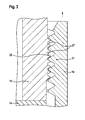
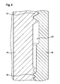
- FIG. 2 to 4 different phases of the assembly process of the clamping nut 18 are shown on the holding body 15.
- the state is shown in which the first toothed region 21 of the clamping nut 18 is located in the region of the second toothed region 22 of the holding body 15.
- a gap 27 is formed between the teeth of the second toothed region 22 of the holding body 15.
- the state is shown in which the first toothed region 21 of the clamping nut 18 in the region of the first toothed region 21 of the holding body 15 arrived. It is essential that at the beginning of the engagement of the thread of the first toothed portion 21 of the clamping nut 18 in the first gear portion of the holding body 15, the output of the winding of the first toothed portion 21 of the clamping nut 18 is still in abutting contact with the second toothed portion 22 of the holding body 15. As a result, the first toothed region 21 of the clamping nut 18 is always in engagement with one of the two toothed regions 21, 22 of the holding body 15, so that slippage or falling through of the clamping nut 18 during assembly on the holding body 15 is avoided.
Landscapes
- Engineering & Computer Science (AREA)
- Manufacturing & Machinery (AREA)
- Chemical & Material Sciences (AREA)
- Combustion & Propulsion (AREA)
- Mechanical Engineering (AREA)
- General Engineering & Computer Science (AREA)
- Fuel-Injection Apparatus (AREA)
Applications Claiming Priority (1)
| Application Number | Priority Date | Filing Date | Title |
|---|---|---|---|
| DE201110076957 DE102011076957A1 (de) | 2011-06-06 | 2011-06-06 | Kraftstoffeinspritzventil für Brennkraftmaschinen |
Publications (2)
| Publication Number | Publication Date |
|---|---|
| EP2532877A1 true EP2532877A1 (fr) | 2012-12-12 |
| EP2532877B1 EP2532877B1 (fr) | 2015-07-29 |
Family
ID=46168230
Family Applications (1)
| Application Number | Title | Priority Date | Filing Date |
|---|---|---|---|
| EP12169087.9A Not-in-force EP2532877B1 (fr) | 2011-06-06 | 2012-05-23 | Soupape d'injection de carburant pour moteurs à combustion interne |
Country Status (3)
| Country | Link |
|---|---|
| US (1) | US8833735B2 (fr) |
| EP (1) | EP2532877B1 (fr) |
| DE (1) | DE102011076957A1 (fr) |
Families Citing this family (2)
| Publication number | Priority date | Publication date | Assignee | Title |
|---|---|---|---|---|
| DE102012208075A1 (de) * | 2012-05-15 | 2013-11-21 | Man Diesel & Turbo Se | Injektor für eine Kraftstoffversorgungsanlage einer Brennkraftmaschine sowie Kraftstoffversorgungsanlage |
| JP6406118B2 (ja) * | 2015-05-07 | 2018-10-17 | 株式会社デンソー | 燃料噴射装置 |
Citations (5)
| Publication number | Priority date | Publication date | Assignee | Title |
|---|---|---|---|---|
| WO2003004866A1 (fr) * | 2001-07-07 | 2003-01-16 | Robert Bosch Gmbh | Dispositif d'injection de carburant haute pression |
| WO2003042531A1 (fr) * | 2001-11-10 | 2003-05-22 | Robert Bosch Gmbh | Soupape permettant de commander le passage de liquides |
| DE102005020833A1 (de) * | 2005-05-04 | 2006-11-09 | Robert Bosch Gmbh | Kraftstoffeinspritzmodul |
| EP1775460A1 (fr) * | 2005-10-17 | 2007-04-18 | Robert Bosch Gmbh | Soupape d'injection de carburant avec une marquage pour aider un positionnement |
| DE102008001330A1 (de) | 2008-04-23 | 2009-10-29 | Robert Bosch Gmbh | Kraftstoffeinspritzventil für Brennkraftmaschinen |
Family Cites Families (4)
| Publication number | Priority date | Publication date | Assignee | Title |
|---|---|---|---|---|
| DE10044933A1 (de) * | 2000-09-12 | 2002-03-21 | Bosch Gmbh Robert | Kraftstoffeinspritzventil für Brennkraftmaschinen |
| JP3928362B2 (ja) * | 2001-02-14 | 2007-06-13 | 株式会社デンソー | 流体移送装置のシール面圧向上構造 |
| DE10121531A1 (de) * | 2001-05-03 | 2002-11-14 | Siemens Ag | Kraftstoffinjektor |
| DE10250720A1 (de) * | 2002-10-31 | 2004-05-13 | Robert Bosch Gmbh | Einspritzventil |
-
2011
- 2011-06-06 DE DE201110076957 patent/DE102011076957A1/de not_active Withdrawn
-
2012
- 2012-05-23 EP EP12169087.9A patent/EP2532877B1/fr not_active Not-in-force
- 2012-06-06 US US13/490,034 patent/US8833735B2/en active Active
Patent Citations (5)
| Publication number | Priority date | Publication date | Assignee | Title |
|---|---|---|---|---|
| WO2003004866A1 (fr) * | 2001-07-07 | 2003-01-16 | Robert Bosch Gmbh | Dispositif d'injection de carburant haute pression |
| WO2003042531A1 (fr) * | 2001-11-10 | 2003-05-22 | Robert Bosch Gmbh | Soupape permettant de commander le passage de liquides |
| DE102005020833A1 (de) * | 2005-05-04 | 2006-11-09 | Robert Bosch Gmbh | Kraftstoffeinspritzmodul |
| EP1775460A1 (fr) * | 2005-10-17 | 2007-04-18 | Robert Bosch Gmbh | Soupape d'injection de carburant avec une marquage pour aider un positionnement |
| DE102008001330A1 (de) | 2008-04-23 | 2009-10-29 | Robert Bosch Gmbh | Kraftstoffeinspritzventil für Brennkraftmaschinen |
Also Published As
| Publication number | Publication date |
|---|---|
| US20120305823A1 (en) | 2012-12-06 |
| US8833735B2 (en) | 2014-09-16 |
| DE102011076957A1 (de) | 2012-12-06 |
| EP2532877B1 (fr) | 2015-07-29 |
Similar Documents
| Publication | Publication Date | Title |
|---|---|---|
| DE102016217923B3 (de) | Rückschlagventil, hochdruckführendes Bauteil und Kraftstoffhochdruckpumpe | |
| DE102007019061B4 (de) | Kopflose Verschraubung | |
| EP2010779B1 (fr) | Dispositif de fixation pour la fixation de conduites à fluide sous haute pression à un accumulateur à fluide sous haute pression | |
| DE19857485A1 (de) | Montagevorrichtung zur Montage und Demontage eines Brennstoffeinspritzventils | |
| EP2532877B1 (fr) | Soupape d'injection de carburant pour moteurs à combustion interne | |
| EP3245433B1 (fr) | Dispositif de liaison pour former une liaison hydraulique | |
| EP2664782A1 (fr) | Injecteur pour une installation d'alimentation en carburant d'un moteur à combustion et installation d'alimentation en carburant | |
| DE102019108382A1 (de) | Gehäuseoberteil für Hochdruckfilter und Hochdruckfilter | |
| DE19908154B4 (de) | Spannelement | |
| EP2592260B1 (fr) | Injecteur de carburant, procédé de montage d'un injecteur de carburant et dispositif de serrage pour le montage d'un injecteur de carburant | |
| DE202007010417U1 (de) | Vorrichtung zur Aufnahme einer Hydraulikflüssigkeit innerhalb eines Kraftfahrzeug-Hydraliksystems | |
| DE102009009851A1 (de) | Kugelmutter für einen Kugelgewindetrieb | |
| EP1775460B1 (fr) | Soupape d'injection de carburant | |
| DE102006014767A1 (de) | Kraftstoffeinspritzeinrichtung für eine mehrzylindrige Brennkraftmaschine | |
| DE10221653A1 (de) | Verbindungsanordnung mit integrierter Drossel | |
| WO2015172950A1 (fr) | Dispositif d'admission de carburant dans un injecteur de carburant et injecteur de carburant | |
| EP1771655B1 (fr) | Ecrou de serrage | |
| EP1793119B1 (fr) | Système d'injection de carburant pour moteur à combustion interne | |
| DE102008057699A1 (de) | Hochdruckpumpe | |
| DE102009054938A1 (de) | Kraftstoffhochdruckpumpe | |
| DE102008057700A1 (de) | Hochdruckpumpe | |
| DE102006053028A1 (de) | Kraftversorgungsanlage einer Großdieselbrennkraftmaschine sowie Hochdruckkraftstoffleitung einer Kraftstoffversorgungsanlage | |
| EP1260704A1 (fr) | Système d'injection d'accumulateur avec des composants à haute pression presentant une resistance mécanique élevée | |
| DE102012004935B4 (de) | Common-Rail | |
| DE102008001016A1 (de) | Kraftstoffeinspritzpumpe sowie Verfahren zur Herstellung einer Kraftstoffeinspritzpumpe |
Legal Events
| Date | Code | Title | Description |
|---|---|---|---|
| PUAI | Public reference made under article 153(3) epc to a published international application that has entered the european phase |
Free format text: ORIGINAL CODE: 0009012 |
|
| AK | Designated contracting states |
Kind code of ref document: A1 Designated state(s): AL AT BE BG CH CY CZ DE DK EE ES FI FR GB GR HR HU IE IS IT LI LT LU LV MC MK MT NL NO PL PT RO RS SE SI SK SM TR |
|
| AX | Request for extension of the european patent |
Extension state: BA ME |
|
| 17P | Request for examination filed |
Effective date: 20130612 |
|
| RBV | Designated contracting states (corrected) |
Designated state(s): AL AT BE BG CH CY CZ DE DK EE ES FI FR GB GR HR HU IE IS IT LI LT LU LV MC MK MT NL NO PL PT RO RS SE SI SK SM TR |
|
| GRAP | Despatch of communication of intention to grant a patent |
Free format text: ORIGINAL CODE: EPIDOSNIGR1 |
|
| INTG | Intention to grant announced |
Effective date: 20150507 |
|
| GRAS | Grant fee paid |
Free format text: ORIGINAL CODE: EPIDOSNIGR3 |
|
| GRAA | (expected) grant |
Free format text: ORIGINAL CODE: 0009210 |
|
| AK | Designated contracting states |
Kind code of ref document: B1 Designated state(s): AL AT BE BG CH CY CZ DE DK EE ES FI FR GB GR HR HU IE IS IT LI LT LU LV MC MK MT NL NO PL PT RO RS SE SI SK SM TR |
|
| REG | Reference to a national code |
Ref country code: GB Ref legal event code: FG4D Free format text: NOT ENGLISH |
|
| REG | Reference to a national code |
Ref country code: CH Ref legal event code: EP |
|
| REG | Reference to a national code |
Ref country code: AT Ref legal event code: REF Ref document number: 739509 Country of ref document: AT Kind code of ref document: T Effective date: 20150815 |
|
| REG | Reference to a national code |
Ref country code: IE Ref legal event code: FG4D Free format text: LANGUAGE OF EP DOCUMENT: GERMAN |
|
| REG | Reference to a national code |
Ref country code: DE Ref legal event code: R096 Ref document number: 502012003904 Country of ref document: DE |
|
| REG | Reference to a national code |
Ref country code: LT Ref legal event code: MG4D |
|
| REG | Reference to a national code |
Ref country code: NL Ref legal event code: MP Effective date: 20150729 |
|
| PG25 | Lapsed in a contracting state [announced via postgrant information from national office to epo] |
Ref country code: NO Free format text: LAPSE BECAUSE OF FAILURE TO SUBMIT A TRANSLATION OF THE DESCRIPTION OR TO PAY THE FEE WITHIN THE PRESCRIBED TIME-LIMIT Effective date: 20151029 Ref country code: GR Free format text: LAPSE BECAUSE OF FAILURE TO SUBMIT A TRANSLATION OF THE DESCRIPTION OR TO PAY THE FEE WITHIN THE PRESCRIBED TIME-LIMIT Effective date: 20151030 Ref country code: LV Free format text: LAPSE BECAUSE OF FAILURE TO SUBMIT A TRANSLATION OF THE DESCRIPTION OR TO PAY THE FEE WITHIN THE PRESCRIBED TIME-LIMIT Effective date: 20150729 Ref country code: LT Free format text: LAPSE BECAUSE OF FAILURE TO SUBMIT A TRANSLATION OF THE DESCRIPTION OR TO PAY THE FEE WITHIN THE PRESCRIBED TIME-LIMIT Effective date: 20150729 Ref country code: FI Free format text: LAPSE BECAUSE OF FAILURE TO SUBMIT A TRANSLATION OF THE DESCRIPTION OR TO PAY THE FEE WITHIN THE PRESCRIBED TIME-LIMIT Effective date: 20150729 |
|
| PG25 | Lapsed in a contracting state [announced via postgrant information from national office to epo] |
Ref country code: HR Free format text: LAPSE BECAUSE OF FAILURE TO SUBMIT A TRANSLATION OF THE DESCRIPTION OR TO PAY THE FEE WITHIN THE PRESCRIBED TIME-LIMIT Effective date: 20150729 Ref country code: PT Free format text: LAPSE BECAUSE OF FAILURE TO SUBMIT A TRANSLATION OF THE DESCRIPTION OR TO PAY THE FEE WITHIN THE PRESCRIBED TIME-LIMIT Effective date: 20151130 Ref country code: IS Free format text: LAPSE BECAUSE OF FAILURE TO SUBMIT A TRANSLATION OF THE DESCRIPTION OR TO PAY THE FEE WITHIN THE PRESCRIBED TIME-LIMIT Effective date: 20151129 Ref country code: ES Free format text: LAPSE BECAUSE OF FAILURE TO SUBMIT A TRANSLATION OF THE DESCRIPTION OR TO PAY THE FEE WITHIN THE PRESCRIBED TIME-LIMIT Effective date: 20150729 Ref country code: SE Free format text: LAPSE BECAUSE OF FAILURE TO SUBMIT A TRANSLATION OF THE DESCRIPTION OR TO PAY THE FEE WITHIN THE PRESCRIBED TIME-LIMIT Effective date: 20150729 Ref country code: PL Free format text: LAPSE BECAUSE OF FAILURE TO SUBMIT A TRANSLATION OF THE DESCRIPTION OR TO PAY THE FEE WITHIN THE PRESCRIBED TIME-LIMIT Effective date: 20150729 Ref country code: RS Free format text: LAPSE BECAUSE OF FAILURE TO SUBMIT A TRANSLATION OF THE DESCRIPTION OR TO PAY THE FEE WITHIN THE PRESCRIBED TIME-LIMIT Effective date: 20150729 |
|
| PG25 | Lapsed in a contracting state [announced via postgrant information from national office to epo] |
Ref country code: NL Free format text: LAPSE BECAUSE OF FAILURE TO SUBMIT A TRANSLATION OF THE DESCRIPTION OR TO PAY THE FEE WITHIN THE PRESCRIBED TIME-LIMIT Effective date: 20150729 |
|
| PG25 | Lapsed in a contracting state [announced via postgrant information from national office to epo] |
Ref country code: EE Free format text: LAPSE BECAUSE OF FAILURE TO SUBMIT A TRANSLATION OF THE DESCRIPTION OR TO PAY THE FEE WITHIN THE PRESCRIBED TIME-LIMIT Effective date: 20150729 Ref country code: DK Free format text: LAPSE BECAUSE OF FAILURE TO SUBMIT A TRANSLATION OF THE DESCRIPTION OR TO PAY THE FEE WITHIN THE PRESCRIBED TIME-LIMIT Effective date: 20150729 Ref country code: SK Free format text: LAPSE BECAUSE OF FAILURE TO SUBMIT A TRANSLATION OF THE DESCRIPTION OR TO PAY THE FEE WITHIN THE PRESCRIBED TIME-LIMIT Effective date: 20150729 Ref country code: CZ Free format text: LAPSE BECAUSE OF FAILURE TO SUBMIT A TRANSLATION OF THE DESCRIPTION OR TO PAY THE FEE WITHIN THE PRESCRIBED TIME-LIMIT Effective date: 20150729 |
|
| REG | Reference to a national code |
Ref country code: DE Ref legal event code: R097 Ref document number: 502012003904 Country of ref document: DE |
|
| REG | Reference to a national code |
Ref country code: FR Ref legal event code: PLFP Year of fee payment: 5 |
|
| PG25 | Lapsed in a contracting state [announced via postgrant information from national office to epo] |
Ref country code: RO Free format text: LAPSE BECAUSE OF FAILURE TO SUBMIT A TRANSLATION OF THE DESCRIPTION OR TO PAY THE FEE WITHIN THE PRESCRIBED TIME-LIMIT Effective date: 20150729 |
|
| PLBE | No opposition filed within time limit |
Free format text: ORIGINAL CODE: 0009261 |
|
| STAA | Information on the status of an ep patent application or granted ep patent |
Free format text: STATUS: NO OPPOSITION FILED WITHIN TIME LIMIT |
|
| 26N | No opposition filed |
Effective date: 20160502 |
|
| PG25 | Lapsed in a contracting state [announced via postgrant information from national office to epo] |
Ref country code: SI Free format text: LAPSE BECAUSE OF FAILURE TO SUBMIT A TRANSLATION OF THE DESCRIPTION OR TO PAY THE FEE WITHIN THE PRESCRIBED TIME-LIMIT Effective date: 20150729 Ref country code: BE Free format text: LAPSE BECAUSE OF NON-PAYMENT OF DUE FEES Effective date: 20160531 |
|
| PG25 | Lapsed in a contracting state [announced via postgrant information from national office to epo] |
Ref country code: LU Free format text: LAPSE BECAUSE OF FAILURE TO SUBMIT A TRANSLATION OF THE DESCRIPTION OR TO PAY THE FEE WITHIN THE PRESCRIBED TIME-LIMIT Effective date: 20160523 |
|
| REG | Reference to a national code |
Ref country code: CH Ref legal event code: PL |
|
| GBPC | Gb: european patent ceased through non-payment of renewal fee |
Effective date: 20160523 |
|
| PG25 | Lapsed in a contracting state [announced via postgrant information from national office to epo] |
Ref country code: LI Free format text: LAPSE BECAUSE OF NON-PAYMENT OF DUE FEES Effective date: 20160531 Ref country code: CH Free format text: LAPSE BECAUSE OF NON-PAYMENT OF DUE FEES Effective date: 20160531 |
|
| REG | Reference to a national code |
Ref country code: IE Ref legal event code: MM4A |
|
| REG | Reference to a national code |
Ref country code: FR Ref legal event code: PLFP Year of fee payment: 6 |
|
| PG25 | Lapsed in a contracting state [announced via postgrant information from national office to epo] |
Ref country code: IE Free format text: LAPSE BECAUSE OF NON-PAYMENT OF DUE FEES Effective date: 20160523 Ref country code: GB Free format text: LAPSE BECAUSE OF NON-PAYMENT OF DUE FEES Effective date: 20160523 |
|
| REG | Reference to a national code |
Ref country code: FR Ref legal event code: PLFP Year of fee payment: 7 |
|
| PG25 | Lapsed in a contracting state [announced via postgrant information from national office to epo] |
Ref country code: SM Free format text: LAPSE BECAUSE OF FAILURE TO SUBMIT A TRANSLATION OF THE DESCRIPTION OR TO PAY THE FEE WITHIN THE PRESCRIBED TIME-LIMIT Effective date: 20150729 Ref country code: CY Free format text: LAPSE BECAUSE OF FAILURE TO SUBMIT A TRANSLATION OF THE DESCRIPTION OR TO PAY THE FEE WITHIN THE PRESCRIBED TIME-LIMIT Effective date: 20150729 Ref country code: HU Free format text: LAPSE BECAUSE OF FAILURE TO SUBMIT A TRANSLATION OF THE DESCRIPTION OR TO PAY THE FEE WITHIN THE PRESCRIBED TIME-LIMIT; INVALID AB INITIO Effective date: 20120523 |
|
| PG25 | Lapsed in a contracting state [announced via postgrant information from national office to epo] |
Ref country code: MK Free format text: LAPSE BECAUSE OF FAILURE TO SUBMIT A TRANSLATION OF THE DESCRIPTION OR TO PAY THE FEE WITHIN THE PRESCRIBED TIME-LIMIT Effective date: 20150729 Ref country code: MT Free format text: LAPSE BECAUSE OF FAILURE TO SUBMIT A TRANSLATION OF THE DESCRIPTION OR TO PAY THE FEE WITHIN THE PRESCRIBED TIME-LIMIT Effective date: 20150729 Ref country code: MC Free format text: LAPSE BECAUSE OF FAILURE TO SUBMIT A TRANSLATION OF THE DESCRIPTION OR TO PAY THE FEE WITHIN THE PRESCRIBED TIME-LIMIT Effective date: 20150729 Ref country code: TR Free format text: LAPSE BECAUSE OF FAILURE TO SUBMIT A TRANSLATION OF THE DESCRIPTION OR TO PAY THE FEE WITHIN THE PRESCRIBED TIME-LIMIT Effective date: 20150729 |
|
| REG | Reference to a national code |
Ref country code: AT Ref legal event code: MM01 Ref document number: 739509 Country of ref document: AT Kind code of ref document: T Effective date: 20170523 |
|
| PG25 | Lapsed in a contracting state [announced via postgrant information from national office to epo] |
Ref country code: BG Free format text: LAPSE BECAUSE OF FAILURE TO SUBMIT A TRANSLATION OF THE DESCRIPTION OR TO PAY THE FEE WITHIN THE PRESCRIBED TIME-LIMIT Effective date: 20150729 |
|
| PG25 | Lapsed in a contracting state [announced via postgrant information from national office to epo] |
Ref country code: AT Free format text: LAPSE BECAUSE OF NON-PAYMENT OF DUE FEES Effective date: 20170523 |
|
| PG25 | Lapsed in a contracting state [announced via postgrant information from national office to epo] |
Ref country code: AL Free format text: LAPSE BECAUSE OF FAILURE TO SUBMIT A TRANSLATION OF THE DESCRIPTION OR TO PAY THE FEE WITHIN THE PRESCRIBED TIME-LIMIT Effective date: 20150729 |
|
| PGFP | Annual fee paid to national office [announced via postgrant information from national office to epo] |
Ref country code: IT Payment date: 20230531 Year of fee payment: 12 Ref country code: FR Payment date: 20230517 Year of fee payment: 12 |
|
| PGFP | Annual fee paid to national office [announced via postgrant information from national office to epo] |
Ref country code: DE Payment date: 20230726 Year of fee payment: 12 |
|
| REG | Reference to a national code |
Ref country code: DE Ref legal event code: R119 Ref document number: 502012003904 Country of ref document: DE |
|
| PG25 | Lapsed in a contracting state [announced via postgrant information from national office to epo] |
Ref country code: DE Free format text: LAPSE BECAUSE OF NON-PAYMENT OF DUE FEES Effective date: 20241203 |
|
| PG25 | Lapsed in a contracting state [announced via postgrant information from national office to epo] |
Ref country code: FR Free format text: LAPSE BECAUSE OF NON-PAYMENT OF DUE FEES Effective date: 20240531 |
|
| PG25 | Lapsed in a contracting state [announced via postgrant information from national office to epo] |
Ref country code: IT Free format text: LAPSE BECAUSE OF NON-PAYMENT OF DUE FEES Effective date: 20240523 |