EP2532885B1 - Windturbine mit einem elektrischen Generator - Google Patents
Windturbine mit einem elektrischen Generator Download PDFInfo
- Publication number
- EP2532885B1 EP2532885B1 EP11169525.0A EP11169525A EP2532885B1 EP 2532885 B1 EP2532885 B1 EP 2532885B1 EP 11169525 A EP11169525 A EP 11169525A EP 2532885 B1 EP2532885 B1 EP 2532885B1
- Authority
- EP
- European Patent Office
- Prior art keywords
- generator
- rotor
- distance
- axis
- wind turbine
- Prior art date
- Legal status (The legal status is an assumption and is not a legal conclusion. Google has not performed a legal analysis and makes no representation as to the accuracy of the status listed.)
- Not-in-force
Links
Images
Classifications
-
- F—MECHANICAL ENGINEERING; LIGHTING; HEATING; WEAPONS; BLASTING
- F03—MACHINES OR ENGINES FOR LIQUIDS; WIND, SPRING, OR WEIGHT MOTORS; PRODUCING MECHANICAL POWER OR A REACTIVE PROPULSIVE THRUST, NOT OTHERWISE PROVIDED FOR
- F03D—WIND MOTORS
- F03D7/00—Controlling wind motors
-
- F—MECHANICAL ENGINEERING; LIGHTING; HEATING; WEAPONS; BLASTING
- F03—MACHINES OR ENGINES FOR LIQUIDS; WIND, SPRING, OR WEIGHT MOTORS; PRODUCING MECHANICAL POWER OR A REACTIVE PROPULSIVE THRUST, NOT OTHERWISE PROVIDED FOR
- F03D—WIND MOTORS
- F03D7/00—Controlling wind motors
- F03D7/02—Controlling wind motors the wind motors having rotation axis substantially parallel to the air flow entering the rotor
- F03D7/0204—Controlling wind motors the wind motors having rotation axis substantially parallel to the air flow entering the rotor for orientation in relation to wind direction
-
- F—MECHANICAL ENGINEERING; LIGHTING; HEATING; WEAPONS; BLASTING
- F03—MACHINES OR ENGINES FOR LIQUIDS; WIND, SPRING, OR WEIGHT MOTORS; PRODUCING MECHANICAL POWER OR A REACTIVE PROPULSIVE THRUST, NOT OTHERWISE PROVIDED FOR
- F03D—WIND MOTORS
- F03D7/00—Controlling wind motors
- F03D7/02—Controlling wind motors the wind motors having rotation axis substantially parallel to the air flow entering the rotor
- F03D7/0272—Controlling wind motors the wind motors having rotation axis substantially parallel to the air flow entering the rotor by measures acting on the electrical generator
-
- F—MECHANICAL ENGINEERING; LIGHTING; HEATING; WEAPONS; BLASTING
- F03—MACHINES OR ENGINES FOR LIQUIDS; WIND, SPRING, OR WEIGHT MOTORS; PRODUCING MECHANICAL POWER OR A REACTIVE PROPULSIVE THRUST, NOT OTHERWISE PROVIDED FOR
- F03D—WIND MOTORS
- F03D9/00—Adaptations of wind motors for special use; Combinations of wind motors with apparatus driven thereby; Wind motors specially adapted for installation in particular locations
- F03D9/20—Wind motors characterised by the driven apparatus
- F03D9/25—Wind motors characterised by the driven apparatus the apparatus being an electrical generator
-
- H—ELECTRICITY
- H02—GENERATION; CONVERSION OR DISTRIBUTION OF ELECTRIC POWER
- H02K—DYNAMO-ELECTRIC MACHINES
- H02K11/00—Structural association of dynamo-electric machines with electric components or with devices for shielding, monitoring or protection
- H02K11/20—Structural association of dynamo-electric machines with electric components or with devices for shielding, monitoring or protection for measuring, monitoring, testing, protecting or switching
-
- H—ELECTRICITY
- H02—GENERATION; CONVERSION OR DISTRIBUTION OF ELECTRIC POWER
- H02K—DYNAMO-ELECTRIC MACHINES
- H02K15/00—Processes or apparatus specially adapted for manufacturing, assembling, maintaining or repairing of dynamo-electric machines
- H02K15/16—Centring rotors within the stators
-
- H—ELECTRICITY
- H02—GENERATION; CONVERSION OR DISTRIBUTION OF ELECTRIC POWER
- H02K—DYNAMO-ELECTRIC MACHINES
- H02K2201/00—Specific aspects not provided for in the other groups of this subclass relating to the magnetic circuits
- H02K2201/03—Machines characterised by aspects of the air-gap between rotor and stator
-
- H—ELECTRICITY
- H02—GENERATION; CONVERSION OR DISTRIBUTION OF ELECTRIC POWER
- H02K—DYNAMO-ELECTRIC MACHINES
- H02K7/00—Arrangements for handling mechanical energy structurally associated with dynamo-electric machines, e.g. structural association with mechanical driving motors or auxiliary dynamo-electric machines
- H02K7/18—Structural association of electric generators with mechanical driving motors, e.g. with turbines
- H02K7/1807—Rotary generators
- H02K7/1823—Rotary generators structurally associated with turbines or similar engines
- H02K7/183—Rotary generators structurally associated with turbines or similar engines wherein the turbine is a wind turbine
- H02K7/1838—Generators mounted in a nacelle or similar structure of a horizontal axis wind turbine
-
- Y—GENERAL TAGGING OF NEW TECHNOLOGICAL DEVELOPMENTS; GENERAL TAGGING OF CROSS-SECTIONAL TECHNOLOGIES SPANNING OVER SEVERAL SECTIONS OF THE IPC; TECHNICAL SUBJECTS COVERED BY FORMER USPC CROSS-REFERENCE ART COLLECTIONS [XRACs] AND DIGESTS
- Y02—TECHNOLOGIES OR APPLICATIONS FOR MITIGATION OR ADAPTATION AGAINST CLIMATE CHANGE
- Y02E—REDUCTION OF GREENHOUSE GAS [GHG] EMISSIONS, RELATED TO ENERGY GENERATION, TRANSMISSION OR DISTRIBUTION
- Y02E10/00—Energy generation through renewable energy sources
- Y02E10/70—Wind energy
- Y02E10/72—Wind turbines with rotation axis in wind direction
Definitions
- the invention relates to a wind turbine comprising an electric generator.
- US 2008/0164697 A1 discusses the use of proximity apparatus for measuring the gap between a rotor and a stator of a wind turbine generator.
- EP 1 870 987 A1 discloses a method and apparatus for monitoring a clearance gap of a rotary machine.
- the inventive electric generator includes a generator rotor and a generator stator concentrically arranged around a generator axis and at a distance from each other.
- the electric generator further comprises a distance sensor arrangement including at least one distance sensor adapted to sense the distance between the generator rotor and the generator stator and to provide a sensor signal comprising an information about the sensed distance.
- the distance sensor arrangement comprises a distance sensor laterally disposed from the generator axis and aligned to sense the distance in a substantially or exactly horizontal direction.
- the distance between the generator stator and the generator rotor is commonly called the air gap. Accordingly, determining the width of the air gap and determining the position of the generator rotor relative to the generator stator are equivalent.
- a distance between the generator rotor and the generator stator may be determined by sensing a distance between a part connected to the stator and a part connected to the rotor.
- the distance between the generator rotor and the generator stator may be determined by sensing a distance between the rotor and a part connected to the stator or by sensing a distance between the stator and a part connected to the rotor.
- the varying forces applied to the wind rotor propagate via the rotor shaft to the electric generator and can cause the generator rotor to temporarily deform or change its center of rotation. Moreover, the loads resulting from the forces can cause wear leading after a while to exceeding tolerances. Both can affect the air gap, i.e. the distance between the generator stator and the generator rotor.
- Monitoring the actual air gap in the electric generator provides several advantages because variations in the rotor position in respect to the stator allows to draw conclusions on the actual forces applied to the wind rotor and the wind turbine rotor blades as well as on their direction of action. For example, it is possible to detect looseness or other structural problems of the electric generator main bearing by detecting a change in the dimension of the air gap.
- an emergency routine can be performed which may include a braking action, pitching the rotor blades or the like.
- the information about the sensed distance between the generator rotor and the generator stator can be evaluated to classify the weather conditions. For example, it may be possible to detect gusty wind which may be more dangerous to the wind turbine structure because unforeseeable variations in wind speed may occur such that it is advisable to already throttle the wind turbine output power at lower (average) wind speeds.
- the variation of wind speed is greater in a horizontal direction than in a vertical direction. Accordingly, the greatest variances of the generator rotor position will also occur in a horizontal direction.
- arranging one distance sensor laterally disposed from the generator axis enables a cost-effective solution employing a low number of distance sensors or just a single distance sensor.
- the distance sensor arrangement comprises a first and a second distance sensor each of which having a respective sensor axis and a parallel projection of the sensor axis of the first distance sensor and of the sensor axis of the second distance sensor onto a plane having a surface normal parallel to the generator axis cross each other.
- the presence of at least two distance sensors that are not arranged in parallel directions is sufficient to provide coordinates in as many dimensions as there are distance sensors.
- a number of two or more distance sensors is preferred because then a position of the electric rotor can be determined in a plane whose surface normal is parallel to the generator axis.
- the parallel projection of the sensor axis of the first distance sensor and of the sensor axis of the second distance sensor cross at an angle of about or exactly 90 degrees.
- the measurements of the two distance sensors are mutually independent which simplifies any computations required for determining the generator rotor position with respect to the generator stator.
- the electric generator may further comprise an evaluation unit connected to the distance sensor arrangement and adapted to determine a position of the generator rotor relative to the generator stator.
- This embodiment of the electric generator provides information about the generator rotor position with respect to the generator stator, which can be processed by other components of the wind turbine.
- the Cartesian coordinates of the generator rotor can be computed requiring very little computing power or be directly derived from the distance sensors' measurements.
- the wind rotor is pivotable about a vertical axis, which is typically substantially perpendicular to a rotational axis of the wind rotor.
- the wind turbine is adapted to pivot the rotor in accordance with the sensor signal from the distance sensor arrangement of the electric generator.
- a wind turbine rotor should face the wind (in the case of an upwind design).
- common wind turbines comprise some means of measuring the wind direction such that the wind rotor may be pivoted to comply with the aforementioned requirement.
- the wind turbine may further be adapted to compare the position of the generator rotor to at least one predetermined threshold position and to generate an alarm signal in correspondence with a result of the comparison. If the air gap drops below a specific threshold, it may be necessary to throttle the output power or brake the wind turbine altogether because the forces applied to the wind rotor and the generator rotor have reached an excessive level. Any such emergency measures can be taken following the generation of an alarm signal in this preferred embodiment of the invention.
- Examples of possible control actions performed in correspondence with the sensor signal may be the generation of an alarm signal, the execution of emergency routines such as braking the wind turbine, pitching the rotor blades to decrease the force applied to the wind rotor, or pivoting the wind rotor of the wind turbine to decrease wind shear.
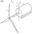
- Fig. 1 shows a wind turbine 10 according to the invention.
- the wind turbine 10 includes a wind turbine rotor 11 which in this exemplary embodiment has three rotor blades 12.
- the wind rotor 11 is connected to an electric generator 14 by means of a rotor shaft 13 which transmits the rotational power provided by the wind rotor 11 to the electric generator 14.
- the electric generator 14 transforms the mechanical power into electric power.
- a transmission including gears may be used to transmit torque from the wind rotor 11 to the electric generator 14, however, such a transmission system entails extra costs and weight and thus is preferably avoided.
- the wind rotor 11, the rotor shaft 13 and the electric generator 14 may be installed at the top of a tower or other support structure not shown in the figure.
- the wind turbine 10 is a horizontal-axis wind turbine.
- the wind turbine rotor 11 is pivotable about a vertical axis 15 in order to be able to orientate the wind rotor 11 of the wind turbine 10 towards the actual wind direction.
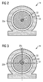
- Fig. 2 shows a first embodiment of an electric generator 14 which may be used in the wind turbine 10 of Fig. 1 .
- the electric generator 14 generally includes a generator stator 21 and a generator rotor 22.
- the fundamental principle of an electric generator is well-understood in the art and therefore will not be explained herein.
- the generator stator 21 may include a base for installing the generator stator 21.
- the generator rotor 22, that is about a generator axis 24, is installed within the generator stator 21 (internal rotor) and may be either directly or indirectly connected to the rotor shaft 13.
- all embodiments of the invention may be implemented in an alternative way where the generator stator is installed within the generator rotor 22 which then rotates around the generator stator (external rotor).
- a distance sensor 25a is arranged on the generator stator 21.
- the distance sensors may be equivalently arranged on the generator stator 21 or on the generator rotor 22, however, when the distance sensor is installed on the generator stator 21, transmission of the distance sensor signal outside the electric generator 14 is facilitated.
- the distance sensor 25a is adapted to measure a distance to the generator rotor 22 and thus a width of the air gap 23.
- the information about the actual width of the air gap 23 provides for a number of advantages. As has already been pointed out, it becomes possible to determine a deviation of the current wind direction from the wind turbine rotor orientation (wind shear) and thus to re-orientate the wind rotor 11 correctly.
- the first embodiment of the electric generator 14 includes a single distance sensor 25a only and therefore represents a low-cost solution. Since the wind moves primarily parallel to the ground even at the height of the wind rotor 11, the wind direction will also vary mostly in a horizontal plane. For this reason the deviations of the generator rotor 22 position will be the greatest in a lateral direction which is why the distance sensor 25a is laterally disposed from the generator axis 24 in the first preferred embodiment. It is safe to assume that as long as the air gap 23 measured at the site of the distance sensor 25a remains within safe boundaries, it will also at any other place in the electric generator 14.
- any number of distance sensors may be present in the electric generator 14.
- the distance sensor(s) can be of any available type such as inductance, light or sound-based designs.
- Fig. 3 shows a second preferred embodiment of an electric generator 14 according to the invention. Items having identical numerals as items in Fig. 2 are identical or functionally equivalent to those in Fig. 2 . Redundant description of them will be omitted for the sake of conciseness.
- the second embodiment largely corresponds to the first embodiment of Fig. 2 but comprises two distance sensors 25b and 25c.
- the two distance sensors 25b and 25c are arranged in such a way that their respective sensor axes cross in the sectional plane through the electric generator 14 of Fig. 3 .
- Preferably the sensor axes cross at a rectangular angle.
- the use of two distance sensors 25b, 25c allows for determining the position of the generator rotor 22 in two dimensions which makes is possible to determine the width of the air gap 23 at any place in the circumference of the generator rotor 22. If the two distance sensors 25b, 25c are arranged perpendicularly to each other, their measurements become linearly independent facilitating the computation of the position of the generator rotor 22.
Landscapes
- Engineering & Computer Science (AREA)
- Life Sciences & Earth Sciences (AREA)
- Sustainable Development (AREA)
- Sustainable Energy (AREA)
- Chemical & Material Sciences (AREA)
- Combustion & Propulsion (AREA)
- Mechanical Engineering (AREA)
- General Engineering & Computer Science (AREA)
- Power Engineering (AREA)
- Microelectronics & Electronic Packaging (AREA)
- Wind Motors (AREA)
Claims (5)
- Windenergieanlage (10) mit einem Generator (14) und einem Windrotor (11), wobei der Generator (14) einen Generatorrotor (22) und einen Generatorstator (21) aufweist, die in einem Abstand (23) zueinander konzentrisch um eine Generatorachse (24) angeordnet sind,
wobei der Generator (14) ferner eine Abstandssensoranordnung mit mindestens einem Abstandssensor (25a, 25b, 25c) umfasst, der so ausgelegt ist, dass er den Abstand (23) zwischen dem Generatorrotor (22) und dem Generatorstator (21) erfasst und ein Sensorsignal bereitstellt, das eine Information über den erfassten Abstand (23) umfasst, dadurch gekennzeichnet, dass die Abstandssensoranordnung einen Abstandssensor (25a, 25b) umfasst, der seitlich zur Generatorachse (24) angeordnet und so ausgerichtet ist, dass er den Abstand (23) in im Wesentlichen oder genau horizontaler Richtung erfasst,
wobei die Abstandssensoranordnung einen ersten und einen zweiten Abstandssensor (25b, 25c) umfasst, die jeweils eine entsprechende Sensorachse aufweisen, und wobei sich eine Parallelprojektion der Sensorachse des ersten Abstandssensors (25b) und der Sensorachse des zweiten Abstandssensors (25c) auf eine Ebene mit einer parallel zur Generatorachse (24) verlaufenden Flächennormalen schneiden, wobei sich die Parallelprojektion der Sensorachse des ersten Abstandssensors (25b) und der Sensorachse des zweiten Abstandssensors (25c) in einem Winkel von etwa oder genau 90 Grad schneiden,
wobei der Windrotor (11) um eine vertikale Achse (15) schwenkbar ist, wobei die Windenergieanlage (10) so ausgelegt ist, dass sie den Windrotor (11) entsprechend dem Sensorsignal aus der Abstandssensoranordnung des Generators (14) verschwenkt. - Windenergieanlage (10) nach Anspruch 1, die ferner eine Auswertungseinheit umfasst, die mit der Abstandssensoranordnung verbunden und so ausgelegt ist, dass sie eine Position des Generatorrotors (22) in Bezug zum Generatorstator (21) bestimmt.
- Windenergieanlage (10) nach Anspruch 2, bei der die Auswertungseinheit so ausgelegt ist, dass sie die Position des Generatorrotors (22) als


- Windenergieanlage (10) nach Anspruch 2, bei der die Auswertungseinheit so ausgelegt ist, dass sie die Position des Generatorrotors (22) als


- Windenergieanlage (10) nach einem der vorhergehenden Ansprüche, die so ausgelegt ist, dass sie die Position des Generatorrotors (22) mit mindestens einer vorgegebenen Schwellwertposition vergleicht und einem Ergebnis des Vergleichs entsprechend ein Warnsignal erzeugt.
Priority Applications (4)
| Application Number | Priority Date | Filing Date | Title |
|---|---|---|---|
| DK11169525.0T DK2532885T3 (en) | 2011-06-10 | 2011-06-10 | Wind turbine with an electric generator |
| EP11169525.0A EP2532885B1 (de) | 2011-06-10 | 2011-06-10 | Windturbine mit einem elektrischen Generator |
| US13/489,678 US20120313374A1 (en) | 2011-06-10 | 2012-06-06 | Electric generator for a wind turbine, wind turbine and method of driving a wind turbine |
| CN2012101879055A CN102820740A (zh) | 2011-06-10 | 2012-06-08 | 风力涡轮机的发电机、风力涡轮机和风力涡轮机驱动方法 |
Applications Claiming Priority (1)
| Application Number | Priority Date | Filing Date | Title |
|---|---|---|---|
| EP11169525.0A EP2532885B1 (de) | 2011-06-10 | 2011-06-10 | Windturbine mit einem elektrischen Generator |
Publications (2)
| Publication Number | Publication Date |
|---|---|
| EP2532885A1 EP2532885A1 (de) | 2012-12-12 |
| EP2532885B1 true EP2532885B1 (de) | 2016-06-01 |
Family
ID=44650957
Family Applications (1)
| Application Number | Title | Priority Date | Filing Date |
|---|---|---|---|
| EP11169525.0A Not-in-force EP2532885B1 (de) | 2011-06-10 | 2011-06-10 | Windturbine mit einem elektrischen Generator |
Country Status (4)
| Country | Link |
|---|---|
| US (1) | US20120313374A1 (de) |
| EP (1) | EP2532885B1 (de) |
| CN (1) | CN102820740A (de) |
| DK (1) | DK2532885T3 (de) |
Families Citing this family (6)
| Publication number | Priority date | Publication date | Assignee | Title |
|---|---|---|---|---|
| EP2975261A1 (de) * | 2014-07-18 | 2016-01-20 | Siemens Aktiengesellschaft | Windkraftanlage mit direkt angetriebenem Generator |
| US10119985B2 (en) * | 2015-10-22 | 2018-11-06 | AISIN Technical Center of America, Inc. | Multi-function speed sensor |
| DK201970457A1 (en) * | 2019-07-10 | 2020-06-25 | Vestas Wind Sys As | Method and apparatus for determining an air gap dimension for an electrical generator in a wind turbine |
| WO2021003576A1 (en) * | 2019-07-10 | 2021-01-14 | Vibrosystm Inc. | Rotary machine, and method of operation thereof |
| EP4064555B1 (de) | 2021-03-25 | 2025-08-06 | Wobben Properties GmbH | Windenergieanlage und verfahren zum steuern einer windenergieanlage |
| CN114039468A (zh) * | 2021-11-05 | 2022-02-11 | 中国能源建设集团江苏省电力建设第一工程有限公司 | 一种大型发电机组转子安装位置动态反馈系统 |
Family Cites Families (6)
| Publication number | Priority date | Publication date | Assignee | Title |
|---|---|---|---|---|
| DE20102029U1 (de) * | 2000-11-10 | 2001-06-28 | Hennchen, Norbert, 29664 Walsrode | Windkraftanlage |
| US7581921B2 (en) * | 2006-06-19 | 2009-09-01 | General Electric Company | Methods and apparatus for controlling rotary machines |
| US7808233B2 (en) * | 2006-06-19 | 2010-10-05 | General Electric Company | Methods and apparatus for monitoring rotary machines |
| US7656135B2 (en) * | 2007-01-05 | 2010-02-02 | General Electric Company | Method and apparatus for controlling rotary machines |
| US7944074B2 (en) * | 2008-03-25 | 2011-05-17 | General Electric Company | Wind turbine direct drive airgap control method and system |
| KR101503249B1 (ko) * | 2008-12-23 | 2015-03-18 | 엑스이엠시 다르윈드 비.브이. | 풍력 터빈 및 풍력 터빈 발전기의 로터와 스테이터 사이의 갭 길이를 모니터링하기 위한 방법 |
-
2011
- 2011-06-10 EP EP11169525.0A patent/EP2532885B1/de not_active Not-in-force
- 2011-06-10 DK DK11169525.0T patent/DK2532885T3/en active
-
2012
- 2012-06-06 US US13/489,678 patent/US20120313374A1/en not_active Abandoned
- 2012-06-08 CN CN2012101879055A patent/CN102820740A/zh active Pending
Also Published As
| Publication number | Publication date |
|---|---|
| EP2532885A1 (de) | 2012-12-12 |
| US20120313374A1 (en) | 2012-12-13 |
| CN102820740A (zh) | 2012-12-12 |
| DK2532885T3 (en) | 2016-08-29 |
Similar Documents
| Publication | Publication Date | Title |
|---|---|---|
| EP2075561B1 (de) | Verfahren und Vorrichtung zur Fehlerverminderung in Rotorbelastungsmessungen | |
| EP2381098B1 (de) | Verfahren, um eine Rotationsposition eines Rotorblattes einer Windturbine und Meßgeräts zu vermessen | |
| US7086834B2 (en) | Methods and apparatus for rotor blade ice detection | |
| EP1760311B1 (de) | Verfahren und Vorrichtung zur betriebsabhängigen Überwachung der Unterteilen einer Windenergieanlage | |
| US11946448B2 (en) | System for contactless displacement measurement of a blade root of a wind turbine | |
| EP2390501B1 (de) | Verfahren und System zur Validierung einer Windturbine | |
| EP2444659B1 (de) | Verfahren und System zur Einstellung eines Betriebsparameters für eine Windturbine | |
| EP3237751B1 (de) | Verfahren und system zur bestimmung der dynamischen verdrehung einer windturbinenschaufel | |
| US9422917B2 (en) | Safety system for a wind turbine | |
| CN203685475U (zh) | 风力涡轮机控制系统及风力涡轮机系统 | |
| EP2532885A1 (de) | Elektrischer Generator für eine Windturbine, Windturbine und Verfahren zum Antrieb einer Windturbine | |
| GB2428748A (en) | Wind turbine control | |
| EP2559897A2 (de) | Verfahren und System zur Erkennung einer ungewöhnlichen Betriebsbedingung einer Windturbine | |
| KR20130046858A (ko) | 풍력 발전기 블레이드 감시 시스템 및 이를 이용한 감시 방법 | |
| KR20230007233A (ko) | 풍력 터빈의 방위각 센서 | |
| KR20130032530A (ko) | 풍력 발전기의 풍향 풍속 측정장치 | |
| KR101379268B1 (ko) | 풍속 보상 운전이 가능한 풍력 발전 시스템 | |
| EP4330543B1 (de) | Steuerungssystem und verfahren zum ausrichten einer gondel einer windturbine mit einem sollgierwinkel | |
| KR20150019778A (ko) | 풍력 발전기의 모션 측정 장치 및 방법 | |
| EP4001641A1 (de) | Verfahren und sensormodul zur bestimmung einer richtung einer windströmung an einem blatt einer windenergieanlage | |
| CN120845271A (zh) | 风轮方位角测量装置的故障诊断方法和系统 | |
| CN122061933A (zh) | 风电机组叶片零位偏移检测方法和设备 |
Legal Events
| Date | Code | Title | Description |
|---|---|---|---|
| PUAI | Public reference made under article 153(3) epc to a published international application that has entered the european phase |
Free format text: ORIGINAL CODE: 0009012 |
|
| AK | Designated contracting states |
Kind code of ref document: A1 Designated state(s): AL AT BE BG CH CY CZ DE DK EE ES FI FR GB GR HR HU IE IS IT LI LT LU LV MC MK MT NL NO PL PT RO RS SE SI SK SM TR |
|
| AX | Request for extension of the european patent |
Extension state: BA ME |
|
| RAP1 | Party data changed (applicant data changed or rights of an application transferred) |
Owner name: SIEMENS AKTIENGESELLSCHAFT |
|
| 17P | Request for examination filed |
Effective date: 20130206 |
|
| 17Q | First examination report despatched |
Effective date: 20131218 |
|
| GRAP | Despatch of communication of intention to grant a patent |
Free format text: ORIGINAL CODE: EPIDOSNIGR1 |
|
| RIC1 | Information provided on ipc code assigned before grant |
Ipc: H02K 11/00 20160101ALI20151204BHEP Ipc: H02K 15/16 20060101ALI20151204BHEP Ipc: H02K 7/18 20060101ALI20151204BHEP Ipc: F03D 9/00 20160101ALI20151204BHEP Ipc: F03D 7/02 20060101ALI20151204BHEP Ipc: F03D 7/00 20060101AFI20151204BHEP |
|
| INTG | Intention to grant announced |
Effective date: 20151222 |
|
| GRAS | Grant fee paid |
Free format text: ORIGINAL CODE: EPIDOSNIGR3 |
|
| GRAA | (expected) grant |
Free format text: ORIGINAL CODE: 0009210 |
|
| AK | Designated contracting states |
Kind code of ref document: B1 Designated state(s): AL AT BE BG CH CY CZ DE DK EE ES FI FR GB GR HR HU IE IS IT LI LT LU LV MC MK MT NL NO PL PT RO RS SE SI SK SM TR |
|
| REG | Reference to a national code |
Ref country code: GB Ref legal event code: FG4D |
|
| REG | Reference to a national code |
Ref country code: CH Ref legal event code: EP Ref country code: AT Ref legal event code: REF Ref document number: 804038 Country of ref document: AT Kind code of ref document: T Effective date: 20160615 |
|
| REG | Reference to a national code |
Ref country code: IE Ref legal event code: FG4D |
|
| REG | Reference to a national code |
Ref country code: DE Ref legal event code: R096 Ref document number: 602011027053 Country of ref document: DE |
|
| REG | Reference to a national code |
Ref country code: DK Ref legal event code: T3 Effective date: 20160822 |
|
| REG | Reference to a national code |
Ref country code: LT Ref legal event code: MG4D |
|
| REG | Reference to a national code |
Ref country code: NL Ref legal event code: MP Effective date: 20160601 |
|
| PG25 | Lapsed in a contracting state [announced via postgrant information from national office to epo] |
Ref country code: NO Free format text: LAPSE BECAUSE OF FAILURE TO SUBMIT A TRANSLATION OF THE DESCRIPTION OR TO PAY THE FEE WITHIN THE PRESCRIBED TIME-LIMIT Effective date: 20160901 Ref country code: FI Free format text: LAPSE BECAUSE OF FAILURE TO SUBMIT A TRANSLATION OF THE DESCRIPTION OR TO PAY THE FEE WITHIN THE PRESCRIBED TIME-LIMIT Effective date: 20160601 Ref country code: LT Free format text: LAPSE BECAUSE OF FAILURE TO SUBMIT A TRANSLATION OF THE DESCRIPTION OR TO PAY THE FEE WITHIN THE PRESCRIBED TIME-LIMIT Effective date: 20160601 |
|
| REG | Reference to a national code |
Ref country code: AT Ref legal event code: MK05 Ref document number: 804038 Country of ref document: AT Kind code of ref document: T Effective date: 20160601 |
|
| PG25 | Lapsed in a contracting state [announced via postgrant information from national office to epo] |
Ref country code: NL Free format text: LAPSE BECAUSE OF FAILURE TO SUBMIT A TRANSLATION OF THE DESCRIPTION OR TO PAY THE FEE WITHIN THE PRESCRIBED TIME-LIMIT Effective date: 20160601 Ref country code: RS Free format text: LAPSE BECAUSE OF FAILURE TO SUBMIT A TRANSLATION OF THE DESCRIPTION OR TO PAY THE FEE WITHIN THE PRESCRIBED TIME-LIMIT Effective date: 20160601 Ref country code: GR Free format text: LAPSE BECAUSE OF FAILURE TO SUBMIT A TRANSLATION OF THE DESCRIPTION OR TO PAY THE FEE WITHIN THE PRESCRIBED TIME-LIMIT Effective date: 20160902 Ref country code: LV Free format text: LAPSE BECAUSE OF FAILURE TO SUBMIT A TRANSLATION OF THE DESCRIPTION OR TO PAY THE FEE WITHIN THE PRESCRIBED TIME-LIMIT Effective date: 20160601 Ref country code: SE Free format text: LAPSE BECAUSE OF FAILURE TO SUBMIT A TRANSLATION OF THE DESCRIPTION OR TO PAY THE FEE WITHIN THE PRESCRIBED TIME-LIMIT Effective date: 20160601 Ref country code: ES Free format text: LAPSE BECAUSE OF FAILURE TO SUBMIT A TRANSLATION OF THE DESCRIPTION OR TO PAY THE FEE WITHIN THE PRESCRIBED TIME-LIMIT Effective date: 20160601 |
|
| PG25 | Lapsed in a contracting state [announced via postgrant information from national office to epo] |
Ref country code: BE Free format text: LAPSE BECAUSE OF NON-PAYMENT OF DUE FEES Effective date: 20160630 |
|
| PG25 | Lapsed in a contracting state [announced via postgrant information from national office to epo] |
Ref country code: SK Free format text: LAPSE BECAUSE OF FAILURE TO SUBMIT A TRANSLATION OF THE DESCRIPTION OR TO PAY THE FEE WITHIN THE PRESCRIBED TIME-LIMIT Effective date: 20160601 Ref country code: RO Free format text: LAPSE BECAUSE OF FAILURE TO SUBMIT A TRANSLATION OF THE DESCRIPTION OR TO PAY THE FEE WITHIN THE PRESCRIBED TIME-LIMIT Effective date: 20160601 Ref country code: IT Free format text: LAPSE BECAUSE OF FAILURE TO SUBMIT A TRANSLATION OF THE DESCRIPTION OR TO PAY THE FEE WITHIN THE PRESCRIBED TIME-LIMIT Effective date: 20160601 Ref country code: EE Free format text: LAPSE BECAUSE OF FAILURE TO SUBMIT A TRANSLATION OF THE DESCRIPTION OR TO PAY THE FEE WITHIN THE PRESCRIBED TIME-LIMIT Effective date: 20160601 Ref country code: IS Free format text: LAPSE BECAUSE OF FAILURE TO SUBMIT A TRANSLATION OF THE DESCRIPTION OR TO PAY THE FEE WITHIN THE PRESCRIBED TIME-LIMIT Effective date: 20161001 Ref country code: CZ Free format text: LAPSE BECAUSE OF FAILURE TO SUBMIT A TRANSLATION OF THE DESCRIPTION OR TO PAY THE FEE WITHIN THE PRESCRIBED TIME-LIMIT Effective date: 20160601 |
|
| REG | Reference to a national code |
Ref country code: CH Ref legal event code: PL |
|
| PG25 | Lapsed in a contracting state [announced via postgrant information from national office to epo] |
Ref country code: SM Free format text: LAPSE BECAUSE OF FAILURE TO SUBMIT A TRANSLATION OF THE DESCRIPTION OR TO PAY THE FEE WITHIN THE PRESCRIBED TIME-LIMIT Effective date: 20160601 Ref country code: AT Free format text: LAPSE BECAUSE OF FAILURE TO SUBMIT A TRANSLATION OF THE DESCRIPTION OR TO PAY THE FEE WITHIN THE PRESCRIBED TIME-LIMIT Effective date: 20160601 Ref country code: PL Free format text: LAPSE BECAUSE OF FAILURE TO SUBMIT A TRANSLATION OF THE DESCRIPTION OR TO PAY THE FEE WITHIN THE PRESCRIBED TIME-LIMIT Effective date: 20160601 Ref country code: BE Free format text: LAPSE BECAUSE OF FAILURE TO SUBMIT A TRANSLATION OF THE DESCRIPTION OR TO PAY THE FEE WITHIN THE PRESCRIBED TIME-LIMIT Effective date: 20160601 Ref country code: PT Free format text: LAPSE BECAUSE OF FAILURE TO SUBMIT A TRANSLATION OF THE DESCRIPTION OR TO PAY THE FEE WITHIN THE PRESCRIBED TIME-LIMIT Effective date: 20161003 |
|
| REG | Reference to a national code |
Ref country code: DE Ref legal event code: R097 Ref document number: 602011027053 Country of ref document: DE |
|
| REG | Reference to a national code |
Ref country code: IE Ref legal event code: MM4A |
|
| PG25 | Lapsed in a contracting state [announced via postgrant information from national office to epo] |
Ref country code: MC Free format text: LAPSE BECAUSE OF FAILURE TO SUBMIT A TRANSLATION OF THE DESCRIPTION OR TO PAY THE FEE WITHIN THE PRESCRIBED TIME-LIMIT Effective date: 20160601 |
|
| PLBE | No opposition filed within time limit |
Free format text: ORIGINAL CODE: 0009261 |
|
| STAA | Information on the status of an ep patent application or granted ep patent |
Free format text: STATUS: NO OPPOSITION FILED WITHIN TIME LIMIT |
|
| PG25 | Lapsed in a contracting state [announced via postgrant information from national office to epo] |
Ref country code: LI Free format text: LAPSE BECAUSE OF NON-PAYMENT OF DUE FEES Effective date: 20160630 Ref country code: CH Free format text: LAPSE BECAUSE OF NON-PAYMENT OF DUE FEES Effective date: 20160630 |
|
| REG | Reference to a national code |
Ref country code: FR Ref legal event code: ST Effective date: 20170331 |
|
| 26N | No opposition filed |
Effective date: 20170302 |
|
| PG25 | Lapsed in a contracting state [announced via postgrant information from national office to epo] |
Ref country code: SI Free format text: LAPSE BECAUSE OF FAILURE TO SUBMIT A TRANSLATION OF THE DESCRIPTION OR TO PAY THE FEE WITHIN THE PRESCRIBED TIME-LIMIT Effective date: 20160601 Ref country code: IE Free format text: LAPSE BECAUSE OF NON-PAYMENT OF DUE FEES Effective date: 20160610 |
|
| PG25 | Lapsed in a contracting state [announced via postgrant information from national office to epo] |
Ref country code: FR Free format text: LAPSE BECAUSE OF NON-PAYMENT OF DUE FEES Effective date: 20160801 |
|
| PG25 | Lapsed in a contracting state [announced via postgrant information from national office to epo] |
Ref country code: HU Free format text: LAPSE BECAUSE OF FAILURE TO SUBMIT A TRANSLATION OF THE DESCRIPTION OR TO PAY THE FEE WITHIN THE PRESCRIBED TIME-LIMIT; INVALID AB INITIO Effective date: 20110610 Ref country code: CY Free format text: LAPSE BECAUSE OF FAILURE TO SUBMIT A TRANSLATION OF THE DESCRIPTION OR TO PAY THE FEE WITHIN THE PRESCRIBED TIME-LIMIT Effective date: 20160601 |
|
| PG25 | Lapsed in a contracting state [announced via postgrant information from national office to epo] |
Ref country code: LU Free format text: LAPSE BECAUSE OF NON-PAYMENT OF DUE FEES Effective date: 20160610 Ref country code: HR Free format text: LAPSE BECAUSE OF FAILURE TO SUBMIT A TRANSLATION OF THE DESCRIPTION OR TO PAY THE FEE WITHIN THE PRESCRIBED TIME-LIMIT Effective date: 20160601 Ref country code: MT Free format text: LAPSE BECAUSE OF NON-PAYMENT OF DUE FEES Effective date: 20160630 Ref country code: MK Free format text: LAPSE BECAUSE OF FAILURE TO SUBMIT A TRANSLATION OF THE DESCRIPTION OR TO PAY THE FEE WITHIN THE PRESCRIBED TIME-LIMIT Effective date: 20160601 Ref country code: TR Free format text: LAPSE BECAUSE OF FAILURE TO SUBMIT A TRANSLATION OF THE DESCRIPTION OR TO PAY THE FEE WITHIN THE PRESCRIBED TIME-LIMIT Effective date: 20160601 |
|
| PG25 | Lapsed in a contracting state [announced via postgrant information from national office to epo] |
Ref country code: BG Free format text: LAPSE BECAUSE OF FAILURE TO SUBMIT A TRANSLATION OF THE DESCRIPTION OR TO PAY THE FEE WITHIN THE PRESCRIBED TIME-LIMIT Effective date: 20160601 |
|
| PG25 | Lapsed in a contracting state [announced via postgrant information from national office to epo] |
Ref country code: AL Free format text: LAPSE BECAUSE OF FAILURE TO SUBMIT A TRANSLATION OF THE DESCRIPTION OR TO PAY THE FEE WITHIN THE PRESCRIBED TIME-LIMIT Effective date: 20160601 |
|
| REG | Reference to a national code |
Ref country code: DE Ref legal event code: R081 Ref document number: 602011027053 Country of ref document: DE Owner name: SIEMENS GAMESA RENEWABLE ENERGY A/S, DK Free format text: FORMER OWNER: SIEMENS AKTIENGESELLSCHAFT, 80333 MUENCHEN, DE |
|
| REG | Reference to a national code |
Ref country code: GB Ref legal event code: 732E Free format text: REGISTERED BETWEEN 20191128 AND 20191204 |
|
| PGFP | Annual fee paid to national office [announced via postgrant information from national office to epo] |
Ref country code: GB Payment date: 20220623 Year of fee payment: 12 Ref country code: DK Payment date: 20220623 Year of fee payment: 12 Ref country code: DE Payment date: 20220621 Year of fee payment: 12 |
|
| REG | Reference to a national code |
Ref country code: DE Ref legal event code: R119 Ref document number: 602011027053 Country of ref document: DE |
|
| REG | Reference to a national code |
Ref country code: DK Ref legal event code: EBP Effective date: 20230630 |
|
| GBPC | Gb: european patent ceased through non-payment of renewal fee |
Effective date: 20230610 |
|
| PG25 | Lapsed in a contracting state [announced via postgrant information from national office to epo] |
Ref country code: DE Free format text: LAPSE BECAUSE OF NON-PAYMENT OF DUE FEES Effective date: 20240103 Ref country code: GB Free format text: LAPSE BECAUSE OF NON-PAYMENT OF DUE FEES Effective date: 20230610 |
|
| PG25 | Lapsed in a contracting state [announced via postgrant information from national office to epo] |
Ref country code: DK Free format text: LAPSE BECAUSE OF NON-PAYMENT OF DUE FEES Effective date: 20230630 |
|
| PG25 | Lapsed in a contracting state [announced via postgrant information from national office to epo] |
Ref country code: DK Free format text: LAPSE BECAUSE OF NON-PAYMENT OF DUE FEES Effective date: 20230630 |