EP2532931A1 - Dichtung und Abdichtungsstruktur - Google Patents
Dichtung und Abdichtungsstruktur Download PDFInfo
- Publication number
- EP2532931A1 EP2532931A1 EP12004271A EP12004271A EP2532931A1 EP 2532931 A1 EP2532931 A1 EP 2532931A1 EP 12004271 A EP12004271 A EP 12004271A EP 12004271 A EP12004271 A EP 12004271A EP 2532931 A1 EP2532931 A1 EP 2532931A1
- Authority
- EP
- European Patent Office
- Prior art keywords
- gasket
- cutout recess
- corner
- opening
- projecting
- Prior art date
- Legal status (The legal status is an assumption and is not a legal conclusion. Google has not performed a legal analysis and makes no representation as to the accuracy of the status listed.)
- Withdrawn
Links
- 229920001971 elastomer Polymers 0.000 claims abstract description 59
- 239000002184 metal Substances 0.000 claims description 8
- 229910052751 metal Inorganic materials 0.000 claims description 8
- 238000005520 cutting process Methods 0.000 claims description 7
- 230000006835 compression Effects 0.000 claims description 6
- 238000007906 compression Methods 0.000 claims description 6
- 238000005452 bending Methods 0.000 claims description 3
- 239000003795 chemical substances by application Substances 0.000 description 10
- 238000007789 sealing Methods 0.000 description 10
- 238000003825 pressing Methods 0.000 description 8
- 239000011324 bead Substances 0.000 description 7
- 238000004140 cleaning Methods 0.000 description 6
- 238000012856 packing Methods 0.000 description 6
- XLYOFNOQVPJJNP-UHFFFAOYSA-N water Substances O XLYOFNOQVPJJNP-UHFFFAOYSA-N 0.000 description 6
- XEEYBQQBJWHFJM-UHFFFAOYSA-N Iron Chemical compound [Fe] XEEYBQQBJWHFJM-UHFFFAOYSA-N 0.000 description 4
- 238000010276 construction Methods 0.000 description 4
- 239000007788 liquid Substances 0.000 description 3
- 239000000463 material Substances 0.000 description 3
- 230000003466 anti-cipated effect Effects 0.000 description 2
- 238000002485 combustion reaction Methods 0.000 description 2
- 239000002826 coolant Substances 0.000 description 2
- 230000006866 deterioration Effects 0.000 description 2
- 239000013013 elastic material Substances 0.000 description 2
- 230000020169 heat generation Effects 0.000 description 2
- 229910052742 iron Inorganic materials 0.000 description 2
- 238000000034 method Methods 0.000 description 2
- 239000011347 resin Substances 0.000 description 2
- 229920005989 resin Polymers 0.000 description 2
- 229910001220 stainless steel Inorganic materials 0.000 description 2
- 239000010935 stainless steel Substances 0.000 description 2
- 229920002943 EPDM rubber Polymers 0.000 description 1
- 229910000831 Steel Inorganic materials 0.000 description 1
- 230000015572 biosynthetic process Effects 0.000 description 1
- 150000001875 compounds Chemical class 0.000 description 1
- 230000000694 effects Effects 0.000 description 1
- 230000005489 elastic deformation Effects 0.000 description 1
- 239000000835 fiber Substances 0.000 description 1
- 229920005560 fluorosilicone rubber Polymers 0.000 description 1
- 230000002401 inhibitory effect Effects 0.000 description 1
- 238000012423 maintenance Methods 0.000 description 1
- 230000014759 maintenance of location Effects 0.000 description 1
- 238000005555 metalworking Methods 0.000 description 1
- 238000000465 moulding Methods 0.000 description 1
- 230000000149 penetrating effect Effects 0.000 description 1
- 230000003014 reinforcing effect Effects 0.000 description 1
- 230000000452 restraining effect Effects 0.000 description 1
- 239000010959 steel Substances 0.000 description 1
- 238000003466 welding Methods 0.000 description 1
Images





Classifications
-
- F—MECHANICAL ENGINEERING; LIGHTING; HEATING; WEAPONS; BLASTING
- F16—ENGINEERING ELEMENTS AND UNITS; GENERAL MEASURES FOR PRODUCING AND MAINTAINING EFFECTIVE FUNCTIONING OF MACHINES OR INSTALLATIONS; THERMAL INSULATION IN GENERAL
- F16J—PISTONS; CYLINDERS; SEALINGS
- F16J15/00—Sealings
- F16J15/02—Sealings between relatively-stationary surfaces
- F16J15/06—Sealings between relatively-stationary surfaces with solid packing compressed between sealing surfaces
- F16J15/10—Sealings between relatively-stationary surfaces with solid packing compressed between sealing surfaces with non-metallic packing
- F16J15/12—Sealings between relatively-stationary surfaces with solid packing compressed between sealing surfaces with non-metallic packing with metal reinforcement or covering
- F16J15/121—Sealings between relatively-stationary surfaces with solid packing compressed between sealing surfaces with non-metallic packing with metal reinforcement or covering with metal reinforcement
-
- F—MECHANICAL ENGINEERING; LIGHTING; HEATING; WEAPONS; BLASTING
- F01—MACHINES OR ENGINES IN GENERAL; ENGINE PLANTS IN GENERAL; STEAM ENGINES
- F01L—CYCLICALLY OPERATING VALVES FOR MACHINES OR ENGINES
- F01L1/00—Valve-gear or valve arrangements, e.g. lift-valve gear
- F01L1/02—Valve drive
- F01L1/04—Valve drive by means of cams, camshafts, cam discs, eccentrics or the like
- F01L1/047—Camshafts
- F01L1/053—Camshafts overhead type
-
- F—MECHANICAL ENGINEERING; LIGHTING; HEATING; WEAPONS; BLASTING
- F01—MACHINES OR ENGINES IN GENERAL; ENGINE PLANTS IN GENERAL; STEAM ENGINES
- F01L—CYCLICALLY OPERATING VALVES FOR MACHINES OR ENGINES
- F01L1/00—Valve-gear or valve arrangements, e.g. lift-valve gear
- F01L1/46—Component parts, details, or accessories, not provided for in preceding subgroups
-
- F—MECHANICAL ENGINEERING; LIGHTING; HEATING; WEAPONS; BLASTING
- F16—ENGINEERING ELEMENTS AND UNITS; GENERAL MEASURES FOR PRODUCING AND MAINTAINING EFFECTIVE FUNCTIONING OF MACHINES OR INSTALLATIONS; THERMAL INSULATION IN GENERAL
- F16J—PISTONS; CYLINDERS; SEALINGS
- F16J15/00—Sealings
- F16J15/02—Sealings between relatively-stationary surfaces
- F16J15/06—Sealings between relatively-stationary surfaces with solid packing compressed between sealing surfaces
- F16J15/062—Sealings between relatively-stationary surfaces with solid packing compressed between sealing surfaces characterised by the geometry of the seat
Definitions
- the present invention relates to a gasket adapted to be inserted for sealing into a cutout recess part of a cylinder head formed for attaching a cam shaft or into the cutout recess part formed on a wall part of a case containing an electric control unit and also relates to a seal structure.
- An exclusive gasket for sealing a cutout recess part is used for the above-mentioned cutout recess part formed on a cylinder head of an internal combustion engine (for example, refer to Patent Literatures 1 to 4).
- an electric control unit such as an inverter, a converter, an electric transformer or the like is used for such a hybrid automobile for controlling operations of the electric motor.
- the electric control unit is contained in a case and the case uses a plug member (hereinafter called as a gasket) which holds an electric wire and a pipe for supplying a cooling medium for restricting heat generation and is fitted into the cutout recess part formed on a case wall to seal the cutout recess part.
- a plug member hereinafter called as a gasket
- PTL 1 discloses a packing (gasket) made of only an elastic material such as rubber and a cutout recess part is formed around a corner part of a cutout recess part in order to avoid high stress when the packing is fitted into the cutout recess part.
- PTL 1 also discloses that such a cutout recess part provided on the surface around the corner part prevents the surface from hardening when the packing is fitted, thereby inhibiting forming of gap and eliminating need for a seal agent.
- the packing is elastically deformed and seal performance of the cutout recess part deteriorates when the packing is applied with inner pressure or is exposed to high-pressure cleaning water because the packing is made of only an elastic material.
- PTL 2 discloses that a cutout recess part of a cylinder head is circular and has a stepped part with different curvatures so as to fit a seal member (gasket) into the circular cutout recess part without causing misalignment and that the seal member is formed in accordance with the shape of the cutout recess part.
- PTL 2 does not consider seal performance of the corner part of the cutout recess part or a so-called three-surface abutting part (where three members such as a cylinder head, a cylinder head cover and a seal member abut mutually, the same hereinafter), so that an auxiliary seal agent such as a liquid gasket is necessary. Therefore, it is anticipated that assembly man-hour is required and the seal agent has to be removed in case of disassembly for maintenance.
- PTL 3 discloses a cylinder head cover gasket wherein a core member is embedded in a plug part (gasket), a flange is formed on the core member, and the flange is designed to abut an end edge of a cutout recess part.
- an auxiliary seal agent is required to be applied especially to a cutout corner part and there are troubles with operation ability in case of assembly and disassembly as mentioned above.
- PTL 4 discloses that a core member has a flange part and a tongue piece part opposite to the flange part and a gasket has a plug part to be fitted into a cutout recess part so as to sandwich both circumferential sides of the cutout recess part with the flange part and the tongue piece part.
- an auxiliary seal agent is required to be applied on a corner part of the cutout recess part in order to secure seal performance and the above-mentioned troubles still remain.
- the present invention has an object to provide a gasket fitted into a cutout recess part for sealing and capable of securing seal performance of a corner part on an opening part side of the cutout recess part without using an auxiliary seal agent and to provide a seal structure.
- a gasket for sealing the cutout recess part of the present invention is characterized by being inserted into the cutout recess part formed on a wall part of a box-shaped member with the opening part on at least one surface in which the cutout recess part communicates with the opening part.
- the gasket comprises an exterior rubber part having a seal surface part elastically contacting the cutout recess part and a core body having higher rigidity than that of the exterior rubber part and covered with the exterior rubber part; the cutout recess part has a chamfered surface at the corner part on the opening part side; and the seal surface part has at a region corresponding to the corner part on the opening part side of the cutout recess part a projecting part formed along the corner part on the opening part side and projecting toward the corner part on the opening part side of the cutout recess part.
- the projecting part may further have a compression allowance portion projecting opposite to the seal surface part.
- the exterior rubber part may have a cover part extending from a side part of the seal surface part so as to cover a region of the wall part corresponding to the cutout recess part from the outside of the box-shaped member when the gasket is fitted into the cutout recess part of the box-shaped member; and the cover part may have an expanding part at the region corresponding to the corner part on the opening part side.
- the core body may have a tongue piece part formed to reach a position corresponding to the projecting part; and the exterior rubber part may have a projection part formed to cover the tongue piece part.
- the core body may be made of metal and the tongue piece part may be made by cutting and raising a part of the core body and bending the cut end side.
- a seal structure including a gasket in which the gasket is adapted to be inserted into the cutout recess part formed on the wall part of the box-shaped member with the opening part on at least one surface in which the cutout recess part communicates with the opening part is characterized in that the cutout recess part has the chamfered surface at the corner part on the opening part side, the gasket comprises an exterior rubber part having the seal surface part elastically contacting the cutout recess part and the core body having higher rigidity than that of the exterior rubber part and covered with the exterior rubber part; and the seal surface part has at the region corresponding to the corner part on the opening part side of the cutout recess part the projecting part formed along the corner part on the opening part side and projecting toward the corner part on the opening part side of the cutout recess part.
- the gasket of the present invention comprises the exterior rubber part having the seal surface part elastically contacting the cutout recess part and the core body which has higher rigidity than that of the exterior rubber part and is covered with the exterior rubber part.
- the exterior rubber part becomes reinforced by the core body, thereby keeping a desired shape so long.
- the exterior rubber part of the present gasket of such a construction it is superior in shape retaining and uncomplicated in assembling, because it is not subject to deformation even when pressing force is applied at the time of fitting into the cutout recess part or even when external force is applied after fitting.
- the present gasket has the projecting part at the region corresponding to the corner part on the opening part side in which the projecting part is formed along and toward the corner part.
- the projecting part can deform along the shape of the chamfered corner part of the cutout recess part, thereby enabling seal performance at the corner part with no need for an auxiliary seal agent.
- the projecting part further has a compression allowance portion projecting opposite to the seal surface part
- the allowance portion facilitates compression of the projecting part and elastic deformation of the tip part along the corner part on the opening part side. Therefore, even when the projecting part and the corner part have tolerance in dimension, the corner part can be preferably sealed.
- the exterior rubber part further has the cover part extending from the side part of the seal surface part formed so as to cover from the outside of the box-shaped member the region of the wall part corresponding to the cutout recess part when the gasket is fitted into the cutout recess part
- the side part of the seal surface part can be covered with the cover part, thereby further improving seal performance at the cutout recess part.
- the cover part further has an expanding part at the region corresponding to the corner part on the opening part side
- the side part on the corner part can also be covered with the expanding part when another sealing object member is integrated with the box-shaped member to be sealed through another annular gasket.
- the core body has the tongue piece part formed to reach the position corresponding to the projecting part and the exterior rubber part has the projection part formed to cover the tongue piece part, so that the cover part is prevented from being blown off even if external force by high-pressure cleaning water is applied, for example, thereby exerting further effective seal performance of the three-surface abutting part by the projecting part.
- the tongue piece part can be easily formed by sheet-metal processing of the core body.
- the projecting part can deform along the shape of the chamfered corner part on the opening part side of the cutout recess part, thereby enabling seal performance at the corner part with no need for an auxiliary seal agent.
- Fig. 1 is a diagrammatic entire perspective view showing one embodiment of the gasket of the present invention together with a first member to be sealed.
- Fig.2 is a partially broken front view and a partially enlarged view illustrating that the gasket is fitted into the first member to be sealed.
- a first member 1 to be sealed is preferably a box-shaped member having an opening part on at least one surface and is shown as a box-shaped member having an opening part 10 on one surface (on an upper surface in Fig.1 , Fig.2 ) of a substantially rectangular parallelepiped constituted with six surfaces in Fig.1 and Fig.2 wherein an upper end surface 11a of circumferential wall parts 11 surrounding the opening 10 is designed to be an objective part to be sealed.
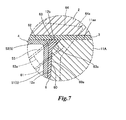
- a second member 2 as another objective member to be sealed such as a cylinder head cover or a cover body is integrated with the upper end surface 11a via another annular gasket 3, as mentioned later (refer to Fig.5 , Fig.7 ).
- One wall part 11A of the circumferential wall parts 11 is formed with a cutout recess part 12 in the form of the letter U which is cut out in depth direction of the box-shaped first member 1 from an upper end surface 11aa of the wall part 11A (half ellipse or half oval).
- a cutout surface 12a of the cutout recess part 12 extends to the upper end surface 11a of the circumferential wall parts 11.
- a corner part on the opening part side 12b (a boundary between the cutout surface 12a and the upper end surface 11a of the circumferential wall parts 11, referred as the corner part 12b hereinafter) which is a corner part of the cutout recess part 12 is chamfered to be an inclining plane surface.
- the gasket 4 comprises an exterior rubber part 6 having a seal surface part 60 elastically contacting the cutout recess part 12 and a core body 5 which has higher rigidity than the exterior rubber part 6 and is covered with the exterior rubber part 6.
- the exterior rubber part 6 is integrally molded on a surface of the core body 5 and is made of a vulcanized molded body of rubber such as FKM, NBR, H-NBR, EPDM, CR, ACM, AEM, VMQ and FVMQ.
- the core body 5 formed by sheet-metal working is placed in a mold having a cavity of predetermined shape, the above-mentioned unvulcanized rubber is injected in the mold and vulcanized, and a molded body integrated with the core body 5 as shown in the figure is obtained.
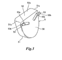
- External surfaces of a longitudinal wall part 50 of the core body 5 and a first lateral wall part 51 are completely covered with the exterior rubber part 6 and the outer shape of the exterior rubber part 6 is formed so as to fit with the cutout recess part 12.
- tongue piece parts 53, 53 and raised piece parts 53a, 53a are embedded in and completely covered with the exterior rubber part 6.
- Parts of the exterior rubber part 6 covering the tongue piece parts 53, 53 are formed as inverted truncated chevron projection parts 61, 61 symmetrical from an anterior view.
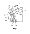
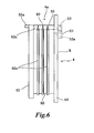
- a surface of the exterior rubber part 6 covering an outer surface of the first lateral wall part 51 is constituted as the seal surface part 60 and a plurality of bead parts 60a are formed on the seal surface part 60 so as to rise in parallel each other along curve of the seal surface part 60 (refer to Fig.1 , Fig.4 , Fig.6 )
- An outer surface of a second lateral wall part 52 is formed with a thin rubber-coated layer 62 constituting a part of the exterior rubber part 6 and a part of an outer surface of the second lateral wall part 52 around the rubber-coated layer 62 is exposed.
- a part 52a of an exposing region facing inside of the first member 1 is formed so as to project further to the inside compared with other part of the core member 5.
- Three bead parts 60a are provided in the figure; however, the number is not limited and one, two, or more than 3 bead parts may be provided. It is effective to provide the bead parts 60a in view of seal performance, which is not considered essential.
- the core body 5 preferably has higher rigidity than the exterior rubber part 6 and may be produced by, for example, a drawing process of sheet metal.
- the core body 5 is formed corresponding to the shape of the cutout recess part 12; an iron sheet metal, a stainless steel metal, or the like is used when the core body 5 is made of sheet metal.
- the core body 5 has the longitudinal wall part 50 of which outer shape from an anterior view (seen from the direction perpendicular to the circumferential wall parts 11) is substantially similar to the shape of the cutout recess part 12 and the first and second lateral wall parts 51, 52 which extend around the longitudinal wall part 50 and face the inside of the first member 1; and the core body 5 is formed in the shape of lateral box (of which section is in the form of transverse letter U).
- the first lateral wall part 51 is bent in the form of the letter U along the shape of the cutout surface 12a of the cutout recess part 12 and the second lateral wall part 52 is formed flat so as to cover an upper end edge of the first lateral wall part 51 and to become parallel to the upper end surface 11a of the circumferential wall parts 11 when the gasket 4 is fitted into the cutout recess part 12.
- the longitudinal wall part 50 is formed with a pair of tongue piece parts 53, 53 by cutting and raising.
- the tongue piece parts 53, 53 are formed in such a manner that the longitudinal wall part 50 is cut and raised in the form of inverted truncated chevron shape (bilaterally symmetrical relative to the longitudinal wall part 50 from an anterior view) and tip ends 53b, 53b of the raised piece parts 53a, 53a perpendicular to the longitudinal wall part 50 are bent at 90 degrees so as to face corner parts 51a, 51a of the first and the second lateral wall parts 51, 52, respectively (refer to Fig.3 ).
- Both upper ends of the U-shaped seal surface part 60 are formed so as to project in opposite directions each other toward the corner part 12b and such projecting regions are formed as projecting parts 63, 63 as shown in Fig.2 .
- the projecting parts 63, 63 are formed on a part of the seal surface part 60 corresponding to the corner part 12b along and toward the shape of the corner part 12b.
- a part of the gasket 4 corresponding to the corner part 12b indicates both corner parts of an upper side part side 4a of the gasket 4 and also indicates a part elastically contacting the corner part 12b when the gasket 4 is fitted into the cutout recess part 12 for sealing.
- Lower surfaces 63a of the projecting parts 63, 63 are chamfered to the inclining plane surface like the corner part 12b and are shaped along a chamfered surface of the corner parts 12b, 12b.
- the projecting parts 63, 63 project in the surface area direction of the wall part 11A and have compression allowance portion formed so as to expand opposite to the seal surface part 60.
- the upper sides of the projecting parts 63, 63 are formed so as to slightly expand upward from the tip end to the base end side and are assembled in such a manner that they expand further than the upper end surface 11aa of the wall part 11A before the first member 1 and the second member 2 are integrated by fastening.
- gap X (refer to the enlarged view in Fig.2 ) between the upper end surface 11aa of the wall part 11A and the annular gasket 3 before the first member 1 and the second member 2 are integrated by fastening.
- the gap X becomes compression allowance portion, so that the projecting parts 63, 63 are easily compressed and tip parts of them are easily deformed in an elastic manner along the corner parts 12b, 12b. Therefore, even if there is dimensional tolerance between the projecting parts 63, 63 and the corner parts 12b. 12b, the corner parts 12b, 12b can be preferably sealed and the seal performance in a so-called three-surface abutting part, which has been thought to be difficult to be sealed, can be improved.
- Circumferential edge of the exterior rubber part 6 covering the longitudinal wall part 50 of the core body 5 is elongated to form a cover part 64 extending in the surface area direction of the wall part 11A.
- the exterior rubber part 6 has the cover part 64 formed by extending a side part of the seal surface part 60 so as to cover a region corresponding to the cutout recess part 12 from the outside of the wall part 11A of the first member 1 (box-shaped member) when the gasket 4 is fitted into the cutout recess part 12.
- the cover part 64 is also formed so as to project from the circumferential edge of the projecting parts 63, 63.
- an inner flange part 65 is formed in an inner part of the seal surface part 60 toward the first member 1 so as to expand in the surface area direction of the wall part 11A.
- a part of the cover part 64 corresponding to the corner part 12b, both upper corner parts from an anterior view in this embodiment, has expanding parts 64a, 64a which expand further than other parts.
- the expanding parts 64a, 64a are formed at a part of the cover part 64 which corresponds to the corner part 12b so as to expand in the surface area direction of the wall part 11A formed with the cutout recess part 12.
- the part corresponding to the corner part 12b indicates a part of the cover part 64 corresponding to a part (namely, projecting part 63) which elastically contacts the corner part 12b under such conditions that the gasket 4 is fitted into the cutout recess part 12 for sealing.
- the part is a region of the cover part 64 corresponding to the position where both corner parts of the upper side part 4a of the gasket 4 are formed.
- the shape of the expanding parts 64a, 64a is not limited to an angular shape which laterally expands and has a triangular projecting top as shown in the figure; however, the projecting part may be rounded.
- the cover part 64 is formed in such a manner that an outer edge keeps constant space (refer to the space Y in the enlarged view in Fig.2 ) along the shape of the cutout surface 12a of the cutout recess part 12 as shown in Fig.1 and Fig.2 .
- the outer surface of the core body 5 is covered with the exterior rubber part 6 in the figure; however, the inner surface may also be covered.
- the present invention is not limited to an embodiment wherein the entire core body 5 is covered with the exterior rubber part 6.
- the exterior rubber part 6 may cover only the first and the second lateral wall parts 51, 52 of the core body 5 or may be filled in space surrounded with the longitudinal wall part 50 and the first and the second lateral wall parts 51, 52 of the core body 5 to form a block body.
- the term "longitudinal” indicates a direction along depth of the first member 1 and "lateral” indicates the perpendicular direction to the wall part 11A of the first member 1.
- the gasket 4 is fitted into the cutout recess part 12 of the first member 1 along the arrow "a" in Fig. 1 .
- the projection part 61 and the exposing part 52a of the second lateral wall part 52 are pressed down with fingers or a simple tool along the arrow "a” as shown with outlined arrows "b", “c” in Fig.4 , thereby fitting the gasket 4.
- the bead part 60a is provided for the seal surface part 60 and is compressed and elastically deformed when the gasket 4 is fitted, so that strong force is required for pressing down.
- the rubber-coated layer 62 which is a seal surface part with the second member 2 (refer to Fig.5 ) is not damaged by fingers or the like.
- the raised piece part 53a which is a part of the core body 5 and the tongue piece part 53 are embedded in the projection part 61, so that the projection part 61 is strengthened by a part of the core body 5 and strong force can be operated for pressing down.
- the first member 1 is, for example, a cylinder head or an inverter case for an automobile engine, and if it is an inverter case, a penetrating retention hole (not shown) for holding a pipe for supplying a cooling medium for restraining heat generation and an electric wire is formed.
- the annular gasket 3 is positioned so as to be placed on the upper side part 4a of the gasket 4 including the upper end surface 11aa of the wall part 11A and the rubber-coated layer 62 as shown in Fig.5 .
- the annular gasket 3 may be a molded body made of only a rubber material or a molded body of rubber compound including inorganic or organic fiber, shape is not limited to be a flat belt, and it may have a bead part along the circumferential direction.
- the second member 2 to be sealed is placed on the first member 1 via the annular gasket 3.
- the projecting part 63 is compressed within the gap X (refer to the enlarged view in Fig.2 ) between the chamfered corner part 12b of the cutout recess part 12 and the second member 2 and is elastically deformed along the flat inclining surface of the corner part 12b.
- tip side of the projecting part 63 fills the gap of the three-surface abutting part, so that the gap can be surely sealed without using an auxiliary seal agent such as a liquid gasket, although it is considered to be difficult to be sealed.
- the gap of the corner part 12b cannot be filled because of dimension difference between the cutout recess part 12 and the gasket 4, and the seal surface part 60 corresponding to the three-surface abutting part may be broken in case of fastening, and causing a fear of losing seal performance.
- a side part of a boundary surface outside of the first member 1 is covered with the cover part 64 extended around the exterior rubber part 6 covering the longitudinal wall part 50 of the core body 5 and cleaning water is prevented from entering the boundary surface even when high-pressure cleaning water is provided.
- a part of the cover part 64 adjacent to the three-surface abutting part (the corner part 12b) is formed so as to expand further than other parts and distance Y (refer to the enlarged view in Fig.2 ) can be secured between an outer edge of the cover part 64 to the boundary of the seal surface part 60 and the cutout surface 12a, even if the corner part 12b is chamfered, so that deterioration of shielding function of the cover part 64 is inhibited around the corner part 12b.
- the cover part 64 in this embodiment of the present invention can preferably shut out intrusion of high-pressure cleaning water into the three-surface abutting part.
- the tongue piece part 53 as a part of the core body 5 extends adjacent to the three-surface abutting part (the corner part 12b) while embedded in the projection part 61 of the exterior rubber part 6, so that the cover part 64 of the three-surface abutting part is not blown off by high-pressure cleaning water, thereby preferably keeping seal performance of the three-surface abutting part.
- Fig.8 shows another embodiment of the present invention in which chamfered shape of the corner part 12b is different from that in the above-mentioned embodiment.
- the corner part 12b is chamfered to be an inclining plane surface in the above-mentioned embodiment; however, it is chamfered in the shape of convex curve (rounding process) in the embodiment in Fig.8 . Therefore, a lower surface of the projecting part 63 is formed in the shape of concave curve corresponding to the shape of the corner part 12b in this embodiment.
- the gasket 4 in this embodiment is also fitted into the cutout recess part 12 of the first member 1 as shown in Fig.1 and the second member 2 is integrated by fastening with the first member 1 via the annular gasket 3.
- the projecting part 63 is compressed together with the annular gasket 3 between the chamfered corner part 12b of the cutout recess part 12 and the second member 2 and is elastically deformed so as to fill space caused by chamfering the corner part 12b.
- an auxiliary seal agent such as a liquid gasket similar to the above-mentioned embodiment.
- Fig.9 shows another embodiment of the present invention in which formation of the projection parts 61, 61 is different from that in the above-mentioned embodiment.
- the projection parts 61, 61 are not the inverted truncated chevron shape as mentioned in the above embodiment, are formed perpendicular to the pressing direction (the arrow "a" in Fig. 1 and Fig.9 ) and are bilaterally symmetric and serially lateral close to the three-surface abutting part.
- the tongue piece parts 53, 53 and the raised piece parts 53a, 53a are embedded in the projection parts 61, 61 as mentioned above; however, plate surfaces of the raised piece parts 53a, 53a are formed in parallel with the pressing direction and the tongue piece parts 53, 53 are formed in the direction perpendicular to the pressing direction "a".
- the direction of the tongue piece parts 53, 53 is misaligned to the three-surface abutting part; however, basic function is the same as that mentioned above.
- the plate surfaces of the raised piece parts 53a, 53a are parallel with the pressing direction "a", so that resistance force to pressing force becomes larger than that in the above-mentioned embodiment because of rib effect.
- the corner part 12b is chamfered in the shape of an inclining plane surface or in the shape of convex curve in the above-mentioned embodiments; however, it may be formed in the shape of a concave curve or in other shape.
- the lower surface of the projecting part 63 is formed so as to fit each chamfered surface.
- the tongue piece part 53 is formed by cutting and raising a part of the core body 5 in the above-mentioned embodiments; however it may be formed on the longitudinal wall part 50 of the core body 5 by welding a tongue piece part which is separately prepared or may be formed by drawing the longitudinal wall part 50.
- a cylinder head and an inverter case for an automobile are exemplified as an object to which the gasket 4 of the present invention is applied; however, objects in other field may be used as long as the gasket is fitted into a recess part formed by cutting a wall part of a box-shaped member and seals the cutout surface.
- the tongue piece part 53 may be omitted as long as there is no fear of damaging the rubber-coated layer 62. If the three-surface abutting part as mentioned above may be adequately sealed by the existence of the projecting part 63, the cover part 64 may be optionally omitted.
- the exterior rubber part 6 of the gasket 4 of the present invention and the annular gasket 3 as shown in Fig.5 may be integrally molded.
- the core body 5 functioning as a reinforcing member of the gasket 4 is not limited to the core body 5 made of an iron steel plate, a stainless steel plate, or the like as mentioned above, and it may be made from resin material, rubber material, or the like as long as it has higher rigidity than the exterior rubber part 6.
- Shape of the core body 5 may be modified such that the longitudinal section is in the form of the letter I (not shown).
- Shape of the core body 5 is not limited to shape fitting the cutout recess part 12, and it may be desirably modified as long as shape of the exterior rubber 6 is maintained.
- the cutout recess part 12 is not limited to be formed by cutting out after the box-shaped member is molded as long as it is cut out so as to communicate with the opening of the box-shaped member and to be in the form of concave shape, and for example it may form a cutout recess part as shown in Fig.1 at the time of molding when the box-shaped member is made from resin.
Landscapes
- Engineering & Computer Science (AREA)
- General Engineering & Computer Science (AREA)
- Mechanical Engineering (AREA)
- Physics & Mathematics (AREA)
- Geometry (AREA)
- Gasket Seals (AREA)
Applications Claiming Priority (1)
| Application Number | Priority Date | Filing Date | Title |
|---|---|---|---|
| JP2011129869A JP5822382B2 (ja) | 2011-06-10 | 2011-06-10 | ガスケット及びシール構造 |
Publications (1)
| Publication Number | Publication Date |
|---|---|
| EP2532931A1 true EP2532931A1 (de) | 2012-12-12 |
Family
ID=46545587
Family Applications (1)
| Application Number | Title | Priority Date | Filing Date |
|---|---|---|---|
| EP12004271A Withdrawn EP2532931A1 (de) | 2011-06-10 | 2012-06-05 | Dichtung und Abdichtungsstruktur |
Country Status (4)
| Country | Link |
|---|---|
| US (1) | US20120313331A1 (de) |
| EP (1) | EP2532931A1 (de) |
| JP (1) | JP5822382B2 (de) |
| CN (1) | CN102818024A (de) |
Families Citing this family (4)
| Publication number | Priority date | Publication date | Assignee | Title |
|---|---|---|---|---|
| JP5626560B2 (ja) * | 2010-02-19 | 2014-11-19 | アイシン精機株式会社 | エンジンのシール構造 |
| US8720905B2 (en) * | 2012-05-17 | 2014-05-13 | GM Global Technology Operations LLC | Sealed t-joint assembly |
| CN103982322B (zh) * | 2014-04-08 | 2017-01-25 | 潍柴动力股份有限公司 | 一种发动机及其碗型塞、该碗型塞的加工方法 |
| US10138841B2 (en) | 2016-10-11 | 2018-11-27 | Ford Global Technologies, Llc | Cam cover assembly cap plug for flexible use of cylinder head accessory drive |
Citations (7)
| Publication number | Priority date | Publication date | Assignee | Title |
|---|---|---|---|---|
| JPS5131975Y1 (de) | 1970-11-26 | 1976-08-10 | ||
| US4396200A (en) * | 1982-04-28 | 1983-08-02 | Toyoda Gosei Co. Ltd. | Packing assembly for sealing between cylinder head and cylinder head cover gasket |
| JPS61167148A (ja) | 1985-01-17 | 1986-07-28 | Suzuki Motor Co Ltd | シリンダ−ヘツドカバ−ガスケツト |
| JPH0225967Y2 (de) | 1984-03-31 | 1990-07-16 | ||
| US6173966B1 (en) * | 1997-10-06 | 2001-01-16 | Freudenberg-Nok General Partnership | T-joint gasket assembly |
| US20020166534A1 (en) * | 2001-05-05 | 2002-11-14 | Harley-Davidson Motor Company Group, Inc. | Cam end cover and gasket assembly |
| JP2009264566A (ja) | 2008-04-30 | 2009-11-12 | Uchiyama Manufacturing Corp | ガスケット |
Family Cites Families (7)
| Publication number | Priority date | Publication date | Assignee | Title |
|---|---|---|---|---|
| JPS5425358A (en) * | 1977-07-28 | 1979-02-26 | Toyota Motor Corp | Packing |
| JPS54156914A (en) * | 1978-05-30 | 1979-12-11 | Toyota Motor Corp | Mounting structure of semi-circular plug for cylinder head |
| US5353953A (en) * | 1993-04-30 | 1994-10-11 | Moriyama Kogyo Kabushiki Kaisha | Sealed meter assembly such as for a speedometer, tachometer, odometer or the like |
| JP4292321B2 (ja) * | 2001-12-07 | 2009-07-08 | 内山工業株式会社 | ガスケット |
| JP4292924B2 (ja) * | 2003-09-11 | 2009-07-08 | Nok株式会社 | ガスケット |
| DE10350127A1 (de) * | 2003-10-28 | 2005-06-02 | International Engine Intellectual Property Company, LLC., Warrenville | Verbrennungsmotor |
| JP2011012794A (ja) * | 2009-07-06 | 2011-01-20 | Uchiyama Manufacturing Corp | ヘッドカバーガスケット |
-
2011
- 2011-06-10 JP JP2011129869A patent/JP5822382B2/ja active Active
-
2012
- 2012-06-05 EP EP12004271A patent/EP2532931A1/de not_active Withdrawn
- 2012-06-07 US US13/490,988 patent/US20120313331A1/en not_active Abandoned
- 2012-06-08 CN CN2012101885836A patent/CN102818024A/zh active Pending
Patent Citations (7)
| Publication number | Priority date | Publication date | Assignee | Title |
|---|---|---|---|---|
| JPS5131975Y1 (de) | 1970-11-26 | 1976-08-10 | ||
| US4396200A (en) * | 1982-04-28 | 1983-08-02 | Toyoda Gosei Co. Ltd. | Packing assembly for sealing between cylinder head and cylinder head cover gasket |
| JPH0225967Y2 (de) | 1984-03-31 | 1990-07-16 | ||
| JPS61167148A (ja) | 1985-01-17 | 1986-07-28 | Suzuki Motor Co Ltd | シリンダ−ヘツドカバ−ガスケツト |
| US6173966B1 (en) * | 1997-10-06 | 2001-01-16 | Freudenberg-Nok General Partnership | T-joint gasket assembly |
| US20020166534A1 (en) * | 2001-05-05 | 2002-11-14 | Harley-Davidson Motor Company Group, Inc. | Cam end cover and gasket assembly |
| JP2009264566A (ja) | 2008-04-30 | 2009-11-12 | Uchiyama Manufacturing Corp | ガスケット |
Also Published As
| Publication number | Publication date |
|---|---|
| CN102818024A (zh) | 2012-12-12 |
| JP2012255514A (ja) | 2012-12-27 |
| JP5822382B2 (ja) | 2015-11-24 |
| US20120313331A1 (en) | 2012-12-13 |
Similar Documents
| Publication | Publication Date | Title |
|---|---|---|
| EP2592308B1 (de) | Gummidichtung und abdichtungsstruktur damit | |
| US11873899B2 (en) | Seal arrangement, battery or control box, motor vehicle and method for producing a seal arrangement | |
| US12066104B2 (en) | Sealing arrangement, battery box or control box, motor vehicle and method for producing a sealing arrangement | |
| JP5800332B2 (ja) | ガスケット | |
| EP2532931A1 (de) | Dichtung und Abdichtungsstruktur | |
| EP2716942A1 (de) | Dichtungsstruktur | |
| JP2008249100A (ja) | 密封構造及びガスケット | |
| JPWO2020026893A1 (ja) | 密封装置及びガスケット | |
| US7147231B2 (en) | Seal feature to prevent bending | |
| CN105604732B (zh) | 密封垫以及密封垫的制造方法 | |
| JP5863258B2 (ja) | 三面合せ部の密封構造 | |
| JP5804500B2 (ja) | ガスケット | |
| US8910611B2 (en) | Fluid delivery system and method of forming fluid delivery system | |
| JP2008291833A (ja) | ガスケット | |
| JP5988248B2 (ja) | 三面合せ部の密封構造 | |
| US10294860B2 (en) | Resin cover removal structure and resin cover | |
| JP5881232B2 (ja) | ガスケット | |
| JP5158950B2 (ja) | ガスケット | |
| JP4317168B2 (ja) | 気密ガスケット | |
| JP5258096B2 (ja) | ガスケット付カバー部材及びその製造方法 | |
| JP5250469B2 (ja) | 密封構造及びガスケット | |
| US20230220914A1 (en) | Gasket | |
| JP2000130591A (ja) | カバーガスケット | |
| JP2018197582A (ja) | ガスケット、及び、エンジン | |
| JP2010144645A (ja) | 樹脂製エンジンカバー |
Legal Events
| Date | Code | Title | Description |
|---|---|---|---|
| PUAI | Public reference made under article 153(3) epc to a published international application that has entered the european phase |
Free format text: ORIGINAL CODE: 0009012 |
|
| AK | Designated contracting states |
Kind code of ref document: A1 Designated state(s): AL AT BE BG CH CY CZ DE DK EE ES FI FR GB GR HR HU IE IS IT LI LT LU LV MC MK MT NL NO PL PT RO RS SE SI SK SM TR |
|
| AX | Request for extension of the european patent |
Extension state: BA ME |
|
| 17P | Request for examination filed |
Effective date: 20130611 |
|
| RBV | Designated contracting states (corrected) |
Designated state(s): AL AT BE BG CH CY CZ DE DK EE ES FI FR GB GR HR HU IE IS IT LI LT LU LV MC MK MT NL NO PL PT RO RS SE SI SK SM TR |
|
| STAA | Information on the status of an ep patent application or granted ep patent |
Free format text: STATUS: THE APPLICATION HAS BEEN WITHDRAWN |
|
| 18W | Application withdrawn |
Effective date: 20150707 |