EP2532937A1 - Mehrfachkupplung - Google Patents
Mehrfachkupplung Download PDFInfo
- Publication number
- EP2532937A1 EP2532937A1 EP20120170238 EP12170238A EP2532937A1 EP 2532937 A1 EP2532937 A1 EP 2532937A1 EP 20120170238 EP20120170238 EP 20120170238 EP 12170238 A EP12170238 A EP 12170238A EP 2532937 A1 EP2532937 A1 EP 2532937A1
- Authority
- EP
- European Patent Office
- Prior art keywords
- connection
- passage portion
- water
- passage
- multiple connector
- Prior art date
- Legal status (The legal status is an assumption and is not a legal conclusion. Google has not performed a legal analysis and makes no representation as to the accuracy of the status listed.)
- Granted
Links
Images


Classifications
-
- F—MECHANICAL ENGINEERING; LIGHTING; HEATING; WEAPONS; BLASTING
- F16—ENGINEERING ELEMENTS AND UNITS; GENERAL MEASURES FOR PRODUCING AND MAINTAINING EFFECTIVE FUNCTIONING OF MACHINES OR INSTALLATIONS; THERMAL INSULATION IN GENERAL
- F16L—PIPES; JOINTS OR FITTINGS FOR PIPES; SUPPORTS FOR PIPES, CABLES OR PROTECTIVE TUBING; MEANS FOR THERMAL INSULATION IN GENERAL
- F16L41/00—Branching pipes; Joining pipes to walls
- F16L41/02—Branch units, e.g. made in one piece, welded, riveted
- F16L41/023—Y- pieces
-
- E—FIXED CONSTRUCTIONS
- E03—WATER SUPPLY; SEWERAGE
- E03C—DOMESTIC PLUMBING INSTALLATIONS FOR FRESH WATER OR WASTE WATER; SINKS
- E03C1/00—Domestic plumbing installations for fresh water or waste water; Sinks
- E03C1/02—Plumbing installations for fresh water
- E03C1/04—Water-basin installations specially adapted to wash-basins or baths
-
- E—FIXED CONSTRUCTIONS
- E03—WATER SUPPLY; SEWERAGE
- E03C—DOMESTIC PLUMBING INSTALLATIONS FOR FRESH WATER OR WASTE WATER; SINKS
- E03C1/00—Domestic plumbing installations for fresh water or waste water; Sinks
- E03C1/02—Plumbing installations for fresh water
- E03C1/04—Water-basin installations specially adapted to wash-basins or baths
- E03C1/0411—Taps specially designed for dispensing boiling water
-
- Y—GENERAL TAGGING OF NEW TECHNOLOGICAL DEVELOPMENTS; GENERAL TAGGING OF CROSS-SECTIONAL TECHNOLOGIES SPANNING OVER SEVERAL SECTIONS OF THE IPC; TECHNICAL SUBJECTS COVERED BY FORMER USPC CROSS-REFERENCE ART COLLECTIONS [XRACs] AND DIGESTS
- Y10—TECHNICAL SUBJECTS COVERED BY FORMER USPC
- Y10T—TECHNICAL SUBJECTS COVERED BY FORMER US CLASSIFICATION
- Y10T137/00—Fluid handling
- Y10T137/8593—Systems
- Y10T137/87571—Multiple inlet with single outlet
- Y10T137/87579—Faucet attachment
Definitions
- the present invention relates to a multiple connector and to a system for mixing-delivering sanitary and/or purified water comprising such a multiple connector.
- the multiple connector according to the invention is suitable for being used for tubes or water piping for domestic usage, particularly for connecting a mixing-delivering valve group and a unit for treating the water with a hydraulic network.
- the treating unit can comprise a filtering unit for food use water, possibly including a device for cooling and/or gassing and/or heating to a temperature near to 100°C said water.
- a system for selectively delivering cold, hot and mixed sanitary water, and also purified water, possibly gassed by means of carbon dioxide.
- Said system comprises a valve group provided with a mixing tap for mixing cold and hot sanitary water supplied by a hydraulic network, and a control tap for delivering purified sanitary water, possibly gassed and/or cooled, flowing from a treating unit which is arranged for filtering, gassing and/or cooling the water.
- connection of the treating unit within said system is obtained upwardly to the valve group by providing a proper "T-shaped" pipe coupling and a ball valve suitable for stopping the flow in the same piping that is connected with the hydraulic network.
- the "T-shaped" pipe coupling also indicated in hydraulics with the term of “pipe tee” or “tee”, comprises a pipe body provided with three connection branches, mutually arranged according to a configuration having just the shape of a "T".
- Each branch defines at its interior a respective passage cavity for the water and is internally provided with a thread of female type for the connection with a respective tube, provided, at one end thereof, with a threaded portion of male type.
- the "T-shaped" pipe coupling comprises a first passage cavity, suitable for receiving at the inlet the cold water provided by the hydraulic network via an inlet tube, a second passage cavity, enabling to deliver the cold water towards the valve group via a first outlet tube, and a third passage cavity, enabling the cold water to reach the treating unit via a second outlet tube.
- the first passage cavity and the second passage cavity are axially aligned to each other, in other words the first passage cavity and the second passage cavity extend along a same first axis, whereas the third passage cavity extends along a second axis, perpendicularly arranged with respect to the first axis.
- the inlet tube results axially aligned, at least near the pipe coupling, with the first outlet tube, whereas the second outlet tube is perpendicularly arranged with respect to the inlet tube and the first outlet tube.
- An object of the invention is to improve the known systems for selectively delivering both cold, hot and mixed sanitary water and purified water for food usage, possibly treated by gassing, and/or cooled and/or made boiling.
- an object of the invention is to provide an economical solution, capable of simplifying and speeding up the connection between hydraulic network, valve group and treating unit, and simultaneously capable of reducing the space occupied, required for mounting the different parts of the system. All above is made possible by a multiple connector according to claim 1.
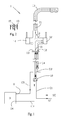
- a system 1 for selectively delivering cold, hot and mixed sanitary water is shown, in an exemplifying and not limiting way, which system 1 is suitable as well for selectively delivering purified water for food usage, with possible gassing by means of carbon dioxide, and/or cooled and/or boiling water, i.e. water at a temperature near to 100°C.
- the system 1 comprises a valve group 2 for delivering sanitary water and purified water, and a unit 3 for treating the water, the unit 3 having the function of filtering, and possibly gassing, by means of addition of carbon dioxide, and/or cooling and/or carrying to a temperature near to 100°C, or about 90°C or, i.e. slightly higher or lower than 90°C, the water provided by the hydraulic network.
- valve group 2 comprises a mixing tap 12, for selectively supplying cold, hot or mixed sanitary water to a first delivering tubular duct 13; the valve group 2 further comprises a control tap 14 for controlling the flow of water treated and provided by the treating unit 3, which water is delivered by a second tubular duct 15, that is parallel or internal to the first delivering duct 13.
- the system 1 comprises a multiple connector 10 according to the invention, which will be described in detail in the following.
- the multiple connector 10 is connected, by means of a first duct C1, with a source SF of cold sanitary water, making part of a conventional hydraulic network, and is connected at the same time, via a second duct C2, with the valve group 2, in order to deliver cold water, flowing from said source SF, to said valve group 2.
- the multiple connector 10 is further connected, via a third duct C3, with the unit 3 for treating the water, in order to deliver cold water, flowing from the source SF, to said treating unit 3.
- the valve group 2 is connected, via a fourth duct C4, with a source SC of hot water, delivered for example by a heating system, or a wall boiler, or a tank of hot water.
- a source SC of hot water delivered for example by a heating system, or a wall boiler, or a tank of hot water.
- a first inlet port 11 for the mixing tap 12 can receive the cold water flowing through the second duct C2 from the multiple connector 10.
- a second inlet port 12 for the mixing tap 12 can receive the hot water flowing through the fourth duct C4.
- a third inlet port 13 for the control tap 14 can receive the treated water flowing from the treating unit 3 through a fifth duct C5.
- the cold water reaching a fourth inlet port 14 of the unit 3 through the third duct C3, once treated, exits from the unit 3 through an outlet port U in order to reach the third inlet port 13 of the valve group 2, in particular in order to reach the control tap 14.
- the multiple connector 10 comprises a body 4 provided, at a first end 8, with a first connection and passage portion 5, suitable for coupling with a duct along a first axis A1.
- the first connection and passage portion 5 is coupled with the first duct C1 in order to receive the cold water provided by the source SF of the hydraulic network.
- the first connection and passage portion 5 defines at its interior a first passage cavity for the water, which first passage cavity at least partially extends along the first axis A1.
- the body 4 of the multiple connector 10 comprises, at a second end 9 opposite the first end 8, a second connection and passage portion 6, suitable for coupling with a duct along a second axis A2.
- the second connection and passage portion 6 is coupled with the second duct C2 in order to deliver the cold water provided by the source SF of the hydraulic network to the valve group 2.
- the second connection and passage portion 6 defines at its interior a second passage cavity for the water, which second passage cavity at least partially extends along the second axis A2.
- the body 4 of the multiple connector 10 further comprises, at the first end 8, a third connection and passage portion 7, suitable for coupling with a duct along a third axis A3.
- the third connection and passage portion 7 is coupled with the third duct C3 in order to deliver the cold water provided by the source SF of the hydraulic network to the treating unit 3.
- the third connection and passage portion 7 defines at its interior a third passage cavity for the water, which third passage cavity at least partially extends along the third axis A3.
- the first, second and third passage cavities are in fluid communication to each other. Consequently, the cold water coming from the cold source and entering the multiple connector 10 through the first portion 5, can flow both into the second connection and passage portion 6 and into the third connection and passage portion 7, in order to reach the mixing tap 12 and/or the treating unit 3 respectively.
- the first connection and passage portion 5, the second connection and passage portion 6 and the third connection and passage portion 7 are mutually arranged to each other so that the first axis A1, the second axis A2 and the third axis A3 are mutually parallel.
- the second connection and passage portion 6 is arranged with respect to the first connection and passage portion 5 and the third connection and passage portion 7 so that the second axis A2 results interposed between the first axis A1 and the third axis A3.
- the multiple connector 10 results more compact with respect to the already known conventional "T-shaped" pipe couplings, and consequently said multiple connector 10 enables, i.a., to remarkably reduce the space requirements of the system.
- first connection and passage portion 5, the second connection and passage portion 6, and the third connection and passage portion 7 extend along axes that are parallel to each other, enables the different connection and passage ducts for the water to be maintained arranged parallel to a same direction, where possible at least near to the multiple connector 10, without the need of imposing large curvatures and changes of direction to the ducts - which large curvatures and changes of direction are conversely unavoidable with the conventional "T-shaped" pipe couplings -, especially in the case that very reduced spaces are available.
- the first duct and the second duct comprise a first flexible tube C1, or a first copper tube, and a second flexible tube C2, or a second copper tube, respectively.
- the first connection and passage portion 5 and the second connection and passage portion 6 are configured for the threaded coupling with the first flexible tube C1 and the second flexible tube C2 respectively.
- the first portion 5 and the second portion 6 are provided with respective female threaded joints, having the size for example of 3/8".
- Other dimensions can also be provided for enabling tubes of different size to be connected, according to the pitch of the screw thread used (M8X1, M10X1, M12X1 etc.).
- the third connection and passage portion 7 is configured for coupling, by means of a quick coupling joint 11, with the third duct C3, that in this case can be a tube C3 of plastic material with diameter of different sizes, for example 8 mm.
- FIG 5 a system 100 is shown that is both structurally and functionally similar to the system 1 previously described. Consequently, for the system 100 the same reference numbers of figure 1 are used, in order to indicate similar or equivalent parts.
- the system 100 of Figure 5 differs from the embodiment of Figure 1 in that the multiple connector 10 is positioned according to a mounting configuration different from the mounting configuration previously described.
- the multiple connector 10 is positioned so that the second connection and passage portion 6 receives at the inlet the cold water provided by the hydraulic network.
- the first duct C1 can comprise in this case an under-sink unit 15.
- the first connection and passage portion 5 is coupled with the second duct C2 in order to deliver the cold water provided by the hydraulic network to the valve group 2.
- the third connection and passage portion 7 is coupled with the third duct C3 in order to deliver the cold water provided by the hydraulic network to the treating unit 3.
- the fourth duct C4 connects the valve group 2 directly with the source SC of hot water, similarly as shown for the embodiment of the system 1. From the comparison of the two different mounting configurations shown in Figure 1 and Figure 5 , it is clear that the multiple connector 10 results very versatile and suitable for being employed according to a plurality of modes of usage.
Landscapes
- Engineering & Computer Science (AREA)
- Health & Medical Sciences (AREA)
- Life Sciences & Earth Sciences (AREA)
- Hydrology & Water Resources (AREA)
- Public Health (AREA)
- Water Supply & Treatment (AREA)
- General Engineering & Computer Science (AREA)
- Mechanical Engineering (AREA)
- Quick-Acting Or Multi-Walled Pipe Joints (AREA)
- Water Treatment By Sorption (AREA)
Applications Claiming Priority (1)
| Application Number | Priority Date | Filing Date | Title |
|---|---|---|---|
| IT001020A ITMI20111020A1 (it) | 2011-06-07 | 2011-06-07 | Connettore multiplo e sistema per la miscelazione-erogazione di acqua sanitaria e depurata comprendente tale connettore multiplo |
Publications (2)
| Publication Number | Publication Date |
|---|---|
| EP2532937A1 true EP2532937A1 (de) | 2012-12-12 |
| EP2532937B1 EP2532937B1 (de) | 2014-03-19 |
Family
ID=44554937
Family Applications (1)
| Application Number | Title | Priority Date | Filing Date |
|---|---|---|---|
| EP20120170238 Not-in-force EP2532937B1 (de) | 2011-06-07 | 2012-05-31 | Mehrfachkupplung |
Country Status (3)
| Country | Link |
|---|---|
| US (1) | US20120312401A1 (de) |
| EP (1) | EP2532937B1 (de) |
| IT (1) | ITMI20111020A1 (de) |
Cited By (1)
| Publication number | Priority date | Publication date | Assignee | Title |
|---|---|---|---|---|
| WO2020165580A1 (en) * | 2019-02-12 | 2020-08-20 | James Kenneth Mcalpine | Multifunction tap |
Families Citing this family (10)
| Publication number | Priority date | Publication date | Assignee | Title |
|---|---|---|---|---|
| CN204704428U (zh) * | 2015-04-18 | 2015-10-14 | 厦门建霖工业有限公司 | 一种双出水龙头 |
| DE102015005098A1 (de) * | 2015-04-22 | 2016-10-27 | Grohe Ag | Sanitärarmatur für zumindest zwei Fluide |
| WO2016185484A1 (en) * | 2015-05-20 | 2016-11-24 | Binay Kumar | Fluid mixer tap or valve |
| EP3359751A4 (de) | 2015-10-08 | 2019-05-22 | AS IP Holdco LLC | Integriertes wasserhahnfiltrierungssystem |
| CN108869804B (zh) * | 2017-05-08 | 2024-04-09 | 漳州松霖智能家居有限公司 | 一种带净水出水功能的出水终端 |
| US10577782B2 (en) * | 2018-01-31 | 2020-03-03 | Guangzhou Seagull Kitchen And Bath Products Co., Ltd. | Device integrated hot and cold tap water and hot and cold purified water |
| CN108730563B (zh) * | 2018-07-30 | 2024-04-19 | 路达(厦门)工业有限公司 | 一种抽取式龙头 |
| USD960322S1 (en) * | 2020-03-17 | 2022-08-09 | Grohe Ag | Faucet |
| US11821183B2 (en) | 2021-11-01 | 2023-11-21 | Jui-Chien Chen | Fast assembling faucet component for dual water sources |
| DE102021130830A1 (de) * | 2021-11-24 | 2023-05-25 | Franke Technology And Trademark Ltd | Armatur, Bad- oder Küchenmöbel mit Armatur sowie Verfahren zum Öffnen und Schließen eines Ablaufs bei einem Bad- oder Küchenmöbel |
Citations (2)
| Publication number | Priority date | Publication date | Assignee | Title |
|---|---|---|---|---|
| US5632300A (en) * | 1993-08-18 | 1997-05-27 | Steamsphere Inc. | Steam trap |
| US20070145743A1 (en) * | 2005-12-14 | 2007-06-28 | Parker-Hannifin Corporation | See-through optically enhanced push-to-connect coupling for indication of tube/conduit insertion |
Family Cites Families (6)
| Publication number | Priority date | Publication date | Assignee | Title |
|---|---|---|---|---|
| GB8926245D0 (en) * | 1989-11-21 | 1990-01-10 | Perrin Robert B | Water tap |
| DE20209799U1 (de) * | 2002-06-24 | 2003-11-13 | Bolderheij Fok Cornelis | Multifunktionsarmatur |
| US6926035B2 (en) * | 2003-07-18 | 2005-08-09 | Astracast, Plc | Water tap |
| CA2573486A1 (en) * | 2006-01-10 | 2007-07-10 | Moen Incorporated | Water filtration system |
| US20070235091A1 (en) * | 2006-04-06 | 2007-10-11 | Yoav Granot | Water tap assembly having a pull-out water-discharge head |
| US8162236B2 (en) * | 2006-04-20 | 2012-04-24 | Masco Corporation Of Indiana | Electronic user interface for electronic mixing of water for residential faucets |
-
2011
- 2011-06-07 IT IT001020A patent/ITMI20111020A1/it unknown
-
2012
- 2012-05-31 EP EP20120170238 patent/EP2532937B1/de not_active Not-in-force
- 2012-06-07 US US13/490,982 patent/US20120312401A1/en not_active Abandoned
Patent Citations (2)
| Publication number | Priority date | Publication date | Assignee | Title |
|---|---|---|---|---|
| US5632300A (en) * | 1993-08-18 | 1997-05-27 | Steamsphere Inc. | Steam trap |
| US20070145743A1 (en) * | 2005-12-14 | 2007-06-28 | Parker-Hannifin Corporation | See-through optically enhanced push-to-connect coupling for indication of tube/conduit insertion |
Cited By (1)
| Publication number | Priority date | Publication date | Assignee | Title |
|---|---|---|---|---|
| WO2020165580A1 (en) * | 2019-02-12 | 2020-08-20 | James Kenneth Mcalpine | Multifunction tap |
Also Published As
| Publication number | Publication date |
|---|---|
| ITMI20111020A1 (it) | 2012-12-08 |
| EP2532937B1 (de) | 2014-03-19 |
| US20120312401A1 (en) | 2012-12-13 |
Similar Documents
| Publication | Publication Date | Title |
|---|---|---|
| EP2532937B1 (de) | Mehrfachkupplung | |
| US8671979B2 (en) | System and valve unit for mixing-delivery sanitary water and/or purified water | |
| US7156425B2 (en) | Quick connect and quick disconnect plumbing apparatus | |
| CN102791304B (zh) | 用于向设备供应高纯度液体的流体系统 | |
| KR20100019511A (ko) | 워터 매니폴드 시스템 및 방법 | |
| US5950575A (en) | Hydronic manifold | |
| CN211875328U (zh) | 一种新型管中管及连接管中管的接头 | |
| CN103582783B (zh) | 辐射器元件以及用于将其连接至管道系统的适配器装置 | |
| CN206670066U (zh) | 燃气热水器 | |
| CN106122610A (zh) | 一种用于预埋自来水管道系统的导向波纹套管 | |
| FI104004B (fi) | Menetelmä ja laitteisto veden kierrättämiseksi putkistossa | |
| CN201373575Y (zh) | 一种可控制水加热器进水的水龙头 | |
| CN211875381U (zh) | 一种用于控制单通道的管中管接头 | |
| AU2012100173A4 (en) | Water Delivery and Mixing Apparatus for Connection to a Water Heater | |
| CN108368697A (zh) | 具有热隔离装置的用于连接至少一个管件和管道的装置 | |
| CN209856782U (zh) | 一种负压自吸式流体死腔破坏装置 | |
| JP2012127486A (ja) | 配管構造 | |
| EP3084316B1 (de) | Wärmetauschervorrichtung | |
| JP2008107080A (ja) | 床暖房システム | |
| CN205859396U (zh) | 壁挂炉紫铜弯管水路系统 | |
| CN106996634A (zh) | 具增压和预热的燃气热水器 | |
| GB2607461A (en) | Method and apparatus for cooling a dispensing station | |
| CN222086306U (zh) | 加热装置及净水系统 | |
| CN203731692U (zh) | 一种改进的快接式热水器供水管路 | |
| CN213334662U (zh) | 热源机组并联管道连接系统 |
Legal Events
| Date | Code | Title | Description |
|---|---|---|---|
| PUAI | Public reference made under article 153(3) epc to a published international application that has entered the european phase |
Free format text: ORIGINAL CODE: 0009012 |
|
| 17P | Request for examination filed |
Effective date: 20120809 |
|
| AK | Designated contracting states |
Kind code of ref document: A1 Designated state(s): AL AT BE BG CH CY CZ DE DK EE ES FI FR GB GR HR HU IE IS IT LI LT LU LV MC MK MT NL NO PL PT RO RS SE SI SK SM TR |
|
| AX | Request for extension of the european patent |
Extension state: BA ME |
|
| REG | Reference to a national code |
Ref country code: DE Ref legal event code: R079 Ref document number: 602012001092 Country of ref document: DE Free format text: PREVIOUS MAIN CLASS: F16L0041020000 Ipc: E03C0001040000 |
|
| RIC1 | Information provided on ipc code assigned before grant |
Ipc: E03C 1/04 20060101AFI20130620BHEP Ipc: F16L 41/02 20060101ALI20130620BHEP |
|
| GRAP | Despatch of communication of intention to grant a patent |
Free format text: ORIGINAL CODE: EPIDOSNIGR1 |
|
| INTG | Intention to grant announced |
Effective date: 20130924 |
|
| GRAS | Grant fee paid |
Free format text: ORIGINAL CODE: EPIDOSNIGR3 |
|
| GRAA | (expected) grant |
Free format text: ORIGINAL CODE: 0009210 |
|
| AK | Designated contracting states |
Kind code of ref document: B1 Designated state(s): AL AT BE BG CH CY CZ DE DK EE ES FI FR GB GR HR HU IE IS IT LI LT LU LV MC MK MT NL NO PL PT RO RS SE SI SK SM TR |
|
| REG | Reference to a national code |
Ref country code: GB Ref legal event code: FG4D |
|
| REG | Reference to a national code |
Ref country code: CH Ref legal event code: EP |
|
| REG | Reference to a national code |
Ref country code: AT Ref legal event code: REF Ref document number: 657798 Country of ref document: AT Kind code of ref document: T Effective date: 20140415 |
|
| REG | Reference to a national code |
Ref country code: IE Ref legal event code: FG4D |
|
| REG | Reference to a national code |
Ref country code: DE Ref legal event code: R096 Ref document number: 602012001092 Country of ref document: DE Effective date: 20140508 |
|
| PG25 | Lapsed in a contracting state [announced via postgrant information from national office to epo] |
Ref country code: NO Free format text: LAPSE BECAUSE OF FAILURE TO SUBMIT A TRANSLATION OF THE DESCRIPTION OR TO PAY THE FEE WITHIN THE PRESCRIBED TIME-LIMIT Effective date: 20140619 Ref country code: LT Free format text: LAPSE BECAUSE OF FAILURE TO SUBMIT A TRANSLATION OF THE DESCRIPTION OR TO PAY THE FEE WITHIN THE PRESCRIBED TIME-LIMIT Effective date: 20140319 |
|
| REG | Reference to a national code |
Ref country code: NL Ref legal event code: VDEP Effective date: 20140319 |
|
| REG | Reference to a national code |
Ref country code: AT Ref legal event code: MK05 Ref document number: 657798 Country of ref document: AT Kind code of ref document: T Effective date: 20140319 |
|
| REG | Reference to a national code |
Ref country code: LT Ref legal event code: MG4D |
|
| PG25 | Lapsed in a contracting state [announced via postgrant information from national office to epo] |
Ref country code: SE Free format text: LAPSE BECAUSE OF FAILURE TO SUBMIT A TRANSLATION OF THE DESCRIPTION OR TO PAY THE FEE WITHIN THE PRESCRIBED TIME-LIMIT Effective date: 20140319 Ref country code: CY Free format text: LAPSE BECAUSE OF FAILURE TO SUBMIT A TRANSLATION OF THE DESCRIPTION OR TO PAY THE FEE WITHIN THE PRESCRIBED TIME-LIMIT Effective date: 20140319 Ref country code: FI Free format text: LAPSE BECAUSE OF FAILURE TO SUBMIT A TRANSLATION OF THE DESCRIPTION OR TO PAY THE FEE WITHIN THE PRESCRIBED TIME-LIMIT Effective date: 20140319 |
|
| PG25 | Lapsed in a contracting state [announced via postgrant information from national office to epo] |
Ref country code: HR Free format text: LAPSE BECAUSE OF FAILURE TO SUBMIT A TRANSLATION OF THE DESCRIPTION OR TO PAY THE FEE WITHIN THE PRESCRIBED TIME-LIMIT Effective date: 20140319 Ref country code: RS Free format text: LAPSE BECAUSE OF FAILURE TO SUBMIT A TRANSLATION OF THE DESCRIPTION OR TO PAY THE FEE WITHIN THE PRESCRIBED TIME-LIMIT Effective date: 20140319 Ref country code: LV Free format text: LAPSE BECAUSE OF FAILURE TO SUBMIT A TRANSLATION OF THE DESCRIPTION OR TO PAY THE FEE WITHIN THE PRESCRIBED TIME-LIMIT Effective date: 20140319 |
|
| PG25 | Lapsed in a contracting state [announced via postgrant information from national office to epo] |
Ref country code: IS Free format text: LAPSE BECAUSE OF FAILURE TO SUBMIT A TRANSLATION OF THE DESCRIPTION OR TO PAY THE FEE WITHIN THE PRESCRIBED TIME-LIMIT Effective date: 20140719 Ref country code: EE Free format text: LAPSE BECAUSE OF FAILURE TO SUBMIT A TRANSLATION OF THE DESCRIPTION OR TO PAY THE FEE WITHIN THE PRESCRIBED TIME-LIMIT Effective date: 20140319 Ref country code: CZ Free format text: LAPSE BECAUSE OF FAILURE TO SUBMIT A TRANSLATION OF THE DESCRIPTION OR TO PAY THE FEE WITHIN THE PRESCRIBED TIME-LIMIT Effective date: 20140319 Ref country code: NL Free format text: LAPSE BECAUSE OF FAILURE TO SUBMIT A TRANSLATION OF THE DESCRIPTION OR TO PAY THE FEE WITHIN THE PRESCRIBED TIME-LIMIT Effective date: 20140319 Ref country code: RO Free format text: LAPSE BECAUSE OF FAILURE TO SUBMIT A TRANSLATION OF THE DESCRIPTION OR TO PAY THE FEE WITHIN THE PRESCRIBED TIME-LIMIT Effective date: 20140319 Ref country code: BG Free format text: LAPSE BECAUSE OF FAILURE TO SUBMIT A TRANSLATION OF THE DESCRIPTION OR TO PAY THE FEE WITHIN THE PRESCRIBED TIME-LIMIT Effective date: 20140619 Ref country code: BE Free format text: LAPSE BECAUSE OF FAILURE TO SUBMIT A TRANSLATION OF THE DESCRIPTION OR TO PAY THE FEE WITHIN THE PRESCRIBED TIME-LIMIT Effective date: 20140319 |
|
| PG25 | Lapsed in a contracting state [announced via postgrant information from national office to epo] |
Ref country code: PL Free format text: LAPSE BECAUSE OF FAILURE TO SUBMIT A TRANSLATION OF THE DESCRIPTION OR TO PAY THE FEE WITHIN THE PRESCRIBED TIME-LIMIT Effective date: 20140319 Ref country code: ES Free format text: LAPSE BECAUSE OF FAILURE TO SUBMIT A TRANSLATION OF THE DESCRIPTION OR TO PAY THE FEE WITHIN THE PRESCRIBED TIME-LIMIT Effective date: 20140319 Ref country code: SK Free format text: LAPSE BECAUSE OF FAILURE TO SUBMIT A TRANSLATION OF THE DESCRIPTION OR TO PAY THE FEE WITHIN THE PRESCRIBED TIME-LIMIT Effective date: 20140319 Ref country code: AT Free format text: LAPSE BECAUSE OF FAILURE TO SUBMIT A TRANSLATION OF THE DESCRIPTION OR TO PAY THE FEE WITHIN THE PRESCRIBED TIME-LIMIT Effective date: 20140319 |
|
| REG | Reference to a national code |
Ref country code: DE Ref legal event code: R119 Ref document number: 602012001092 Country of ref document: DE |
|
| PG25 | Lapsed in a contracting state [announced via postgrant information from national office to epo] |
Ref country code: PT Free format text: LAPSE BECAUSE OF FAILURE TO SUBMIT A TRANSLATION OF THE DESCRIPTION OR TO PAY THE FEE WITHIN THE PRESCRIBED TIME-LIMIT Effective date: 20140721 Ref country code: LU Free format text: LAPSE BECAUSE OF FAILURE TO SUBMIT A TRANSLATION OF THE DESCRIPTION OR TO PAY THE FEE WITHIN THE PRESCRIBED TIME-LIMIT Effective date: 20140531 |
|
| PLBE | No opposition filed within time limit |
Free format text: ORIGINAL CODE: 0009261 |
|
| STAA | Information on the status of an ep patent application or granted ep patent |
Free format text: STATUS: NO OPPOSITION FILED WITHIN TIME LIMIT |
|
| PG25 | Lapsed in a contracting state [announced via postgrant information from national office to epo] |
Ref country code: MC Free format text: LAPSE BECAUSE OF FAILURE TO SUBMIT A TRANSLATION OF THE DESCRIPTION OR TO PAY THE FEE WITHIN THE PRESCRIBED TIME-LIMIT Effective date: 20140319 Ref country code: DK Free format text: LAPSE BECAUSE OF FAILURE TO SUBMIT A TRANSLATION OF THE DESCRIPTION OR TO PAY THE FEE WITHIN THE PRESCRIBED TIME-LIMIT Effective date: 20140319 |
|
| 26N | No opposition filed |
Effective date: 20141222 |
|
| REG | Reference to a national code |
Ref country code: IE Ref legal event code: MM4A |
|
| REG | Reference to a national code |
Ref country code: DE Ref legal event code: R119 Ref document number: 602012001092 Country of ref document: DE Effective date: 20141202 |
|
| REG | Reference to a national code |
Ref country code: FR Ref legal event code: ST Effective date: 20150130 |
|
| PG25 | Lapsed in a contracting state [announced via postgrant information from national office to epo] |
Ref country code: IE Free format text: LAPSE BECAUSE OF NON-PAYMENT OF DUE FEES Effective date: 20140531 Ref country code: DE Free format text: LAPSE BECAUSE OF NON-PAYMENT OF DUE FEES Effective date: 20141202 |
|
| PG25 | Lapsed in a contracting state [announced via postgrant information from national office to epo] |
Ref country code: FR Free format text: LAPSE BECAUSE OF NON-PAYMENT OF DUE FEES Effective date: 20140602 |
|
| PG25 | Lapsed in a contracting state [announced via postgrant information from national office to epo] |
Ref country code: SI Free format text: LAPSE BECAUSE OF FAILURE TO SUBMIT A TRANSLATION OF THE DESCRIPTION OR TO PAY THE FEE WITHIN THE PRESCRIBED TIME-LIMIT Effective date: 20140319 |
|
| REG | Reference to a national code |
Ref country code: CH Ref legal event code: PL |
|
| PG25 | Lapsed in a contracting state [announced via postgrant information from national office to epo] |
Ref country code: LI Free format text: LAPSE BECAUSE OF NON-PAYMENT OF DUE FEES Effective date: 20150531 Ref country code: CH Free format text: LAPSE BECAUSE OF NON-PAYMENT OF DUE FEES Effective date: 20150531 |
|
| PG25 | Lapsed in a contracting state [announced via postgrant information from national office to epo] |
Ref country code: MT Free format text: LAPSE BECAUSE OF FAILURE TO SUBMIT A TRANSLATION OF THE DESCRIPTION OR TO PAY THE FEE WITHIN THE PRESCRIBED TIME-LIMIT Effective date: 20140319 |
|
| PG25 | Lapsed in a contracting state [announced via postgrant information from national office to epo] |
Ref country code: SM Free format text: LAPSE BECAUSE OF FAILURE TO SUBMIT A TRANSLATION OF THE DESCRIPTION OR TO PAY THE FEE WITHIN THE PRESCRIBED TIME-LIMIT Effective date: 20140319 |
|
| PG25 | Lapsed in a contracting state [announced via postgrant information from national office to epo] |
Ref country code: GR Free format text: LAPSE BECAUSE OF FAILURE TO SUBMIT A TRANSLATION OF THE DESCRIPTION OR TO PAY THE FEE WITHIN THE PRESCRIBED TIME-LIMIT Effective date: 20140620 |
|
| PG25 | Lapsed in a contracting state [announced via postgrant information from national office to epo] |
Ref country code: HU Free format text: LAPSE BECAUSE OF FAILURE TO SUBMIT A TRANSLATION OF THE DESCRIPTION OR TO PAY THE FEE WITHIN THE PRESCRIBED TIME-LIMIT; INVALID AB INITIO Effective date: 20120531 Ref country code: TR Free format text: LAPSE BECAUSE OF FAILURE TO SUBMIT A TRANSLATION OF THE DESCRIPTION OR TO PAY THE FEE WITHIN THE PRESCRIBED TIME-LIMIT Effective date: 20140319 |
|
| GBPC | Gb: european patent ceased through non-payment of renewal fee |
Effective date: 20160531 |
|
| PG25 | Lapsed in a contracting state [announced via postgrant information from national office to epo] |
Ref country code: GB Free format text: LAPSE BECAUSE OF NON-PAYMENT OF DUE FEES Effective date: 20160531 |
|
| PG25 | Lapsed in a contracting state [announced via postgrant information from national office to epo] |
Ref country code: MK Free format text: LAPSE BECAUSE OF FAILURE TO SUBMIT A TRANSLATION OF THE DESCRIPTION OR TO PAY THE FEE WITHIN THE PRESCRIBED TIME-LIMIT Effective date: 20140319 |
|
| PG25 | Lapsed in a contracting state [announced via postgrant information from national office to epo] |
Ref country code: AL Free format text: LAPSE BECAUSE OF FAILURE TO SUBMIT A TRANSLATION OF THE DESCRIPTION OR TO PAY THE FEE WITHIN THE PRESCRIBED TIME-LIMIT Effective date: 20140319 |
|
| PGFP | Annual fee paid to national office [announced via postgrant information from national office to epo] |
Ref country code: IT Payment date: 20230524 Year of fee payment: 12 |
|
| PG25 | Lapsed in a contracting state [announced via postgrant information from national office to epo] |
Ref country code: IT Free format text: LAPSE BECAUSE OF NON-PAYMENT OF DUE FEES Effective date: 20240531 |