EP2532942A2 - Lichtemittierende Diodenglühlampe - Google Patents
Lichtemittierende Diodenglühlampe Download PDFInfo
- Publication number
- EP2532942A2 EP2532942A2 EP12171310A EP12171310A EP2532942A2 EP 2532942 A2 EP2532942 A2 EP 2532942A2 EP 12171310 A EP12171310 A EP 12171310A EP 12171310 A EP12171310 A EP 12171310A EP 2532942 A2 EP2532942 A2 EP 2532942A2
- Authority
- EP
- European Patent Office
- Prior art keywords
- terminal
- heat sink
- light emitting
- disposed
- holes
- Prior art date
- Legal status (The legal status is an assumption and is not a legal conclusion. Google has not performed a legal analysis and makes no representation as to the accuracy of the status listed.)
- Withdrawn
Links
- 239000012212 insulator Substances 0.000 claims abstract description 82
- 238000009413 insulation Methods 0.000 claims description 17
- 238000005452 bending Methods 0.000 claims description 10
- 230000017525 heat dissipation Effects 0.000 claims description 5
- 239000002184 metal Substances 0.000 abstract description 12
- 238000000034 method Methods 0.000 description 9
- 230000008901 benefit Effects 0.000 description 4
- 238000010292 electrical insulation Methods 0.000 description 4
- 238000005286 illumination Methods 0.000 description 3
- 230000000903 blocking effect Effects 0.000 description 2
- 230000002708 enhancing effect Effects 0.000 description 2
- 230000007613 environmental effect Effects 0.000 description 1
Images








Classifications
-
- F—MECHANICAL ENGINEERING; LIGHTING; HEATING; WEAPONS; BLASTING
- F21—LIGHTING
- F21V—FUNCTIONAL FEATURES OR DETAILS OF LIGHTING DEVICES OR SYSTEMS THEREOF; STRUCTURAL COMBINATIONS OF LIGHTING DEVICES WITH OTHER ARTICLES, NOT OTHERWISE PROVIDED FOR
- F21V29/00—Protecting lighting devices from thermal damage; Cooling or heating arrangements specially adapted for lighting devices or systems
- F21V29/50—Cooling arrangements
- F21V29/70—Cooling arrangements characterised by passive heat-dissipating elements, e.g. heat-sinks
- F21V29/74—Cooling arrangements characterised by passive heat-dissipating elements, e.g. heat-sinks with fins or blades
- F21V29/77—Cooling arrangements characterised by passive heat-dissipating elements, e.g. heat-sinks with fins or blades with essentially identical diverging planar fins or blades, e.g. with fan-like or star-like cross-section
-
- F—MECHANICAL ENGINEERING; LIGHTING; HEATING; WEAPONS; BLASTING
- F21—LIGHTING
- F21K—NON-ELECTRIC LIGHT SOURCES USING LUMINESCENCE; LIGHT SOURCES USING ELECTROCHEMILUMINESCENCE; LIGHT SOURCES USING CHARGES OF COMBUSTIBLE MATERIAL; LIGHT SOURCES USING SEMICONDUCTOR DEVICES AS LIGHT-GENERATING ELEMENTS; LIGHT SOURCES NOT OTHERWISE PROVIDED FOR
- F21K9/00—Light sources using semiconductor devices as light-generating elements, e.g. using light-emitting diodes [LED] or lasers
- F21K9/20—Light sources comprising attachment means
- F21K9/23—Retrofit light sources for lighting devices with a single fitting for each light source, e.g. for substitution of incandescent lamps with bayonet or threaded fittings
-
- F—MECHANICAL ENGINEERING; LIGHTING; HEATING; WEAPONS; BLASTING
- F21—LIGHTING
- F21K—NON-ELECTRIC LIGHT SOURCES USING LUMINESCENCE; LIGHT SOURCES USING ELECTROCHEMILUMINESCENCE; LIGHT SOURCES USING CHARGES OF COMBUSTIBLE MATERIAL; LIGHT SOURCES USING SEMICONDUCTOR DEVICES AS LIGHT-GENERATING ELEMENTS; LIGHT SOURCES NOT OTHERWISE PROVIDED FOR
- F21K9/00—Light sources using semiconductor devices as light-generating elements, e.g. using light-emitting diodes [LED] or lasers
- F21K9/20—Light sources comprising attachment means
- F21K9/23—Retrofit light sources for lighting devices with a single fitting for each light source, e.g. for substitution of incandescent lamps with bayonet or threaded fittings
- F21K9/238—Arrangement or mounting of circuit elements integrated in the light source
-
- F—MECHANICAL ENGINEERING; LIGHTING; HEATING; WEAPONS; BLASTING
- F21—LIGHTING
- F21V—FUNCTIONAL FEATURES OR DETAILS OF LIGHTING DEVICES OR SYSTEMS THEREOF; STRUCTURAL COMBINATIONS OF LIGHTING DEVICES WITH OTHER ARTICLES, NOT OTHERWISE PROVIDED FOR
- F21V19/00—Fastening of light sources or lamp holders
- F21V19/001—Fastening of light sources or lamp holders the light sources being semiconductors devices, e.g. LEDs
- F21V19/003—Fastening of light source holders, e.g. of circuit boards or substrates holding light sources
- F21V19/004—Fastening of light source holders, e.g. of circuit boards or substrates holding light sources by deformation of parts or snap action mountings, e.g. using clips
-
- F—MECHANICAL ENGINEERING; LIGHTING; HEATING; WEAPONS; BLASTING
- F21—LIGHTING
- F21V—FUNCTIONAL FEATURES OR DETAILS OF LIGHTING DEVICES OR SYSTEMS THEREOF; STRUCTURAL COMBINATIONS OF LIGHTING DEVICES WITH OTHER ARTICLES, NOT OTHERWISE PROVIDED FOR
- F21V23/00—Arrangement of electric circuit elements in or on lighting devices
- F21V23/003—Arrangement of electric circuit elements in or on lighting devices the elements being electronics drivers or controllers for operating the light source, e.g. for a LED array
- F21V23/004—Arrangement of electric circuit elements in or on lighting devices the elements being electronics drivers or controllers for operating the light source, e.g. for a LED array arranged on a substrate, e.g. a printed circuit board
- F21V23/006—Arrangement of electric circuit elements in or on lighting devices the elements being electronics drivers or controllers for operating the light source, e.g. for a LED array arranged on a substrate, e.g. a printed circuit board the substrate being distinct from the light source holder
-
- F—MECHANICAL ENGINEERING; LIGHTING; HEATING; WEAPONS; BLASTING
- F21—LIGHTING
- F21V—FUNCTIONAL FEATURES OR DETAILS OF LIGHTING DEVICES OR SYSTEMS THEREOF; STRUCTURAL COMBINATIONS OF LIGHTING DEVICES WITH OTHER ARTICLES, NOT OTHERWISE PROVIDED FOR
- F21V3/00—Globes; Bowls; Cover glasses
-
- F—MECHANICAL ENGINEERING; LIGHTING; HEATING; WEAPONS; BLASTING
- F21—LIGHTING
- F21Y—INDEXING SCHEME ASSOCIATED WITH SUBCLASSES F21K, F21L, F21S and F21V, RELATING TO THE FORM OR THE KIND OF THE LIGHT SOURCES OR OF THE COLOUR OF THE LIGHT EMITTED
- F21Y2115/00—Light-generating elements of semiconductor light sources
- F21Y2115/10—Light-emitting diodes [LED]
Definitions
- the present invention relates to light bulbs and, more particularly, to a type of light emitting diode bulbs.
- LEDs light emitting diodes
- the use of LEDs in light bulbs has become prevalent, and the low power consumption of LEDs meets the trend of environmental protection.
- LEDs generally have the light source output characteristics of point light source, high brightness and narrow light beam.
- the mechanical characteristics and reliability of LEDs are also different from those of traditional luminaires. Accordingly, pertinent testing standards with respect to solid-state lighting are being developed in various countries for a variety of applications, including roadside illumination, outdoor illumination, indoor illumination, etc.
- an LED lamp board and a driving circuit are electrically coupled through a connector.
- noise tends to increase as the length of the wire increases.
- the height of the connector on the LED lamp board may result in light being covered.
- the LED lamp board and a heat sink are typically affixed together by one or more screws. This nevertheless increases the time of assembly.
- the driving circuit and a screw thread are usually electrically coupled together via wires, the time of assembly would be further increased.
- An objective of the present invention is to provide an LED bulb that can be assembled relatively more easily with shorter assembly time and lower cost of assembly.
- an LED bulb may comprise a heat sink, an insulator cover, a light emitting device package, a plurality of conductive terminals, a driving circuit, a holder, a screw head and an electrode.
- the heat sink may comprise a component receiving surface, a plurality of fastening through holes, and a plurality of positioning through holes. The fastening through holes and the positioning through holes may be disposed on the component receiving surface.
- the insulator cover may be disposed on the heat sink and may include an opening.
- the insulator cover may comprise a plurality of hooking parts and a plurality of terminal receptacles. The hooking parts and the terminal receptacles may protrude from a surface of the insulator cover.
- Each of at least some of the hooking parts may be configured to be engaged with a respective one of the fastening through holes and each of at least some of the terminal receptacles may be configured to pass through a respective one of the positioning through holes to be engaged with the respective positioning through hole such that the insulator cover is affixed to the heat sink.
- the light emitting device package may be disposed on the component receiving surface of the heat sink and may include a plurality of driving electrodes. The light emitting device package may be disposed between the insulator cover and the heat sink.
- the light emitting device package may be affixed to the insulator cover with the opening of the insulator cover exposing a portion of the light emitting device package.
- the plurality of conductive terminals may be respectively disposed in the terminal receptacle through holes of the terminal receptacles.
- the conductive terminals may extend outwardly and in physical contact with the driving electrodes of the light emitting device package.
- the driving circuit may output a current signal to drive the light emitting device package.
- the driving circuit may comprise a plurality of upper conductive rods and a plurality of lower conductive rods.
- the upper conductive rods may be in physical contact with the conductive terminals.
- the holder may comprise a holding protrusion.
- the holder may be configured to be assembled to the heat sink via the holding protrusion.
- the screw thread may be coupled to the holder and may comprise a screw thread through hole.
- the screw thread may be electrically connected to a first one of the lower conductive rods.
- the electrode may be disposed in the screw thread through hole and electrically connected to a second one of the lower conductive rods.
- the LE D bulb may further comprise a lens disposed on and coupled to the heat sink.
- the lens may at least partially or totally cover the light emitting device package and the insulator cover.
- the LE D bulb may further comprise an insulation box disposed in the heat sink and containing the driving circuit therein.
- the insulation box may comprise a plurality of holes. The upper conductive rods and the lower conductive rods may traverse through the holes to be exposed outside of the insulation box.
- each of at least some of the conductive terminals respectively may comprise a terminal body and an extension electrode.
- the terminal body may comprise a terminal through hole and a plurality of hooking parts in the terminal through hole.
- the hooking parts may protrude in a direction away from the respective terminal through hole.
- the extension electrodes of the conductive terminals may extend outwardly and physically contact the driving electrodes of the light emitting device package.
- a sidewall of the terminal receptacle through hole of each of at least some of the terminal receptacles may respectively comprise a protrusion.
- the hooking parts of the terminal bodies and the protrusions of the terminal receptacles may be engaged together.
- each of at least some of the conductive terminals may comprise a terminal bending part in the respective terminal through hole that is electrically connected with at least some of the upper conductive rods.
- the light emitting device package may comprise a first surface and a second surface opposite to the first surface.
- the second surface may be connected to the component receiving surface and in physical contact with the heat sink.
- the driving electrodes may be disposed on the first surface.
- the heat sink may comprise a plurality of heat dissipation fins disposed around the heat sink.
- an LED bulb may comprise a heat sink, a light emitting device package, a driving circuit, a holder, a plurality of conductive terminals, a screw thread and an electrode.
- the heat sink may include a component receiving surface.
- the light emitting device package may be disposed on the component receiving surface and may comprise a plurality of driving electrodes.
- the driving circuit may output a current signal to drive the light emitting device package.
- the driving circuit may comprise a plurality of upper conductive rods and a plurality of lower conductive rods.
- the upper conductive rods may be electrically connected with the driving electrodes.
- the holder may comprise a holding protrusion and a plurality of terminal receptacles.
- Each of at least some of the terminal receptacles may comprise a respective terminal receptacle through hole.
- At least some of the lower conductive rods may be disposed in the terminal receptacle through holes.
- the plurality of conductive terminals may be respectively disposed in the terminal receptacle through holes of the terminal receptacles and in physical contact with the lower conductive rods.
- the screw thread may be coupled to the holder and may include a screw thread through hole.
- the electrode may be disposed in the screw thread through hole of the screw thread.
- the conductive terminals may extend outwardly and be in physical contact with the screw thread and the electrode such that each of the screw thread and the electrode is electrically connected with a respective one of the lower conductive rods.
- the LED bulb may further comprise a lens disposed on and coupled to the heat sink.
- the lens may at least partially or totally cover the light emitting device package.
- the LED bulb may further comprise an insulation box disposed in the heat sink and containing the driving circuit therein.
- the insulation box may comprise a plurality of holes, the upper conductive rods and the lower conductive rods traversing through the holes to be exposed outside of the insulation box.
- each of at least some of the conductive terminals respectively may comprise a terminal body and an extension electrode.
- the terminal body may comprise a terminal through hole and a plurality of hooking parts in the terminal through hole.
- the hooking parts may protrude in a direction away from the respective terminal through hole.
- the extension electrodes of the conductive terminals may extend outwardly and physically contact the screw thread and the electrode.
- a sidewall of the terminal receptacle through hole of each of at least some of the terminal receptacles may respectively comprise a protrusion.
- the hooking parts of the terminal bodies and the protrusions of the terminal receptacles may be engaged together.
- each of at least some of the conductive terminals may comprise a terminal bending part in the respective terminal through hole that is bent toward the respective terminal through hole and electrically connected with at least some of the lower conductive rods.
- the light emitting device package may comprise a first surface and a second surface opposite to the first surface.
- the second surface may be connected to the component receiving surface and in physical contact with the heat sink.
- the driving electrodes may be disposed on the first surface.
- the heat sink may comprise a plurality of heat dissipation fins disposed around the heat sink.
- an LED bulb may comprise a heat sink, an insulator cover, a light emitting device package, a plurality of conductive terminals, a driving circuit, a holder, a plurality of second conductive terminals, a screw thread and an electrode.
- the heat sink may comprise a component receiving surface, a plurality of fastening through holes, and a plurality of positioning through holes. The fastening through holes and the positioning through holes may be disposed on the component receiving surface.
- the insulator cover may be disposed on the heat sink and may include an opening.
- the insulator cover may comprise a plurality of first hooking parts and a plurality of first terminal receptacles.
- the first hooking parts and the first terminal receptacles may protrude from a surface of the insulator cover.
- Each of at least some of the first hooking parts may be configured to be engaged with a respective one of the fastening through holes and each of at least some of the first terminal receptacles may be configured to pass through a respective one of the positioning through holes to be engaged with the respective positioning through hole such that the insulator cover is affixed to the heat sink.
- Each of at least some of the first terminal receptacles respectively may include a first terminal receptacle through hole.
- the light emitting device package may be disposed on the component receiving surface of the heat sink and may include a plurality of driving electrodes.
- the light emitting device package may be disposed between the insulator cover and the heat sink.
- the light emitting device package may be affixed to the insulator cover with the opening of the insulator cover exposing a portion of the light emitting device package.
- the plurality of first conductive terminals may be respectively disposed in the first terminal receptacle through holes of the first terminal receptacles.
- the first conductive terminals may extend outwardly and may be in physical contact with the driving electrodes of the light emitting device package.
- the driving circuit may comprise a plurality of upper conductive rods and a plurality of lower conductive rods.
- the upper conductive rods may be in physical contact with the first conductive terminals.
- the holder may comprise a holding protrusion and a plurality of second terminal receptacles.
- the holder may be configured to be assembled to the heat sink via the holding protrusion.
- Each of at least some of the second terminal receptacles may respectively comprise a second terminal receptacle through hole.
- the lower conductive rods may be disposed in the second terminal receptacle through holes.
- the plurality of second conductive terminals may be disposed in the second terminal receptacle through holes of the second terminal receptacles and in physical contact with the lower conductive rods.
- the screw thread may be coupled to the holder and may comprise a screw thread through hole. The screw thread may be electrically connected to a first one of the lower conductive rods.
- the electrode may be disposed in the screw thread through hole and electrically connected to a second one of the lower conductive rods.
- the second conductive terminals may extend outwardly and physically contact the screw thread and the electrode such that the screw thread and the electrode are electrically connected with the first one of the lower conductive rods and the second one of the lower conductive rods, respectively.
- the LED bulb may further comprise a lens disposed on and coupled to the heat sink.
- the lens may at least partially or totally cover the light emitting device package and the insulator cover.
- the insulator cover and the heat sink are affixed together using a hooking method. Accordingly, the light emitting device package, which is disposed between the insulator cover and the heat sink, can be affixed thereto at the same time. That is, hooks may be directly used for assembling to the heat sink to reduce the cost and time associated with using screws to do the same. This advantageously enhances electrical insulation. Moreover, the first conductive terminals and the second conductive terminals may be respectively affixed to the insulator cover and the holder using the hooking method.
- connection terminals This design reduces not only the noise associated with traditional connection by wires but also the time it takes to render electrical connection (e.g., wiring) as well as the light being covered by connection terminals. Furthermore, as the LED bulb may be assembled together using hooks, engagement or other fastening methods without the use of screws, potential hazards to a user when disassembling the LED bulb may be avoided.
- Figure 1A is a perspective view of an LED bulb in accordance with an embodiment of the preset disclosure.
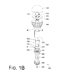
- Figure 1 B is an exploded view of the LED bulb of Figure 1A .
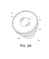
- Figure 2A is a top perspective view of a heat sink as shown in Figure 1 B .
- Figure 2B is a bottom plane view of the heat sink of Figure 2A .
- Figure 3A is a top perspective view of an insulator cover as shown in Figure 1 B .
- Figure 3B is a bottom perspective view of the insulator cover as shown in Figure 1 B .
- Figure 4A is a top view of an assembly of an insulator cover, a light emitting device package and a heat sink in accordance with an embodiment of the present disclosure.
- Figure 4B is a cross-sectional view along the line AA' of Figure 4A .
- Figure 5A is a top view of a first conductive terminal and the insulator cover as shown in Figure 1 B when unassembled.
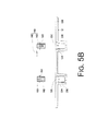
- Figure 5B is a cross-sectional view along the line BB's of Figure 5A .
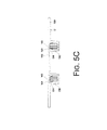
- Figure 5C is a cross-sectional view of the first conductive terminal and the insulator cover of Figure 5B when assembled.
- Figure 6A is a top perspective view of the first conductive terminal as shown in Figure 1 B .
- Figure 6B is a cross-sectional view of the first conductive terminal and the driving circuit as shown in Figure 1 B when assembled.
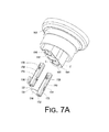
- Figure 7A is a perspective view of a holder and two second conductive terminals as shown in Figure 1B when unassembled.
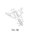
- Figure 7B is a cross-sectional view along the line CC' of Figure 7A .
- Figure 8A is a perspective view of the holder and the two conductive terminals of Figure 7A when assembled.
- Figure 8B is a cross-sectional view along the line DD' of Figure 8A .
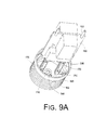
- Figure 9A is a perspective view of an assembly of the driving circuit, second conductive terminals, a metal screw thread and a electrode as shown in Figure 1 B .
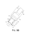
- Figure 9B is a perspective view of the driving circuit, the second conductive terminals and the electrode as shown in Figure 1 B when assembled.
- Figure 1A illustrates a perspective view of an LED bulb in accordance with an embodiment of the present disclosure.
- Figure 1 B illustrates an exploded view of the LED bulb of Figure 1A .
- an LED bulb 1000 comprises a heat sink 1100, an insulator cover 1200, a light emitting device package 1300, a plurality of first conductive terminals 1400, a driving circuit 1500, a holder 1600, a plurality of second conductive terminals 1700, a metal screw thread 1800, and an electrode 1900.
- the insulator cover 1200 may be affixed to the heat sink 1100 by a hooking configuration.
- the light emitting device package 1300 which is disposed between the insulator cover 1200 and the heat sink 1100, can be affixed thereto at the same time. That is, hooks may be utilized for assembly to the heat sink 1100.
- This design reduces the time and cost of assembly compared to the case of assembly using screws, in addition to enhancing the electrical insulation thereof.
- the first conductive terminals 1400 and the second conductive terminals 1700 may be respectively affixed to insulator cover 1200 and the holder 1600. This design reduces not only the noise associated with traditional connection by wires but also the time it takes to render electrical connection (e.g., wiring) as well as the light being covered by connection terminals.
- the following description pertains to the structure and benefits of an embodiment of the LED bulb 1000.
- FIG 2A illustrates a top perspective view of the heat sink as shown in Figure 1 B .
- Figure 2B illustrates a bottom plane view of the heat sink of Figure 2A .
- the heat sink 1100 comprises a component receiving surface S1, a plurality of fastening through holes 1120 and a plurality of positioning through holes 1140.
- the fastening through holes 1120 and the positioning through holes 1140 are disposed on the component receiving surface S1.
- each of at least some of the fastening through holes 1120 comprises a respective fastening protrusion 1122 therein.
- the component receiving surface S1 may be a recess of the heat sink 1100 that receives and positions the light emitting device package 1300, to be described below. As shown in Figure 2A , in some other embodiments, the component receiving surface S1 is not a recess of the heat sink 1100, depending on the need of the user. That is, the component receiving surface S1 may be a recess of the heat sink 1100 when the light emitting device package 1300 needs to be positioned therein.
- the heat sink 1100 may include a plurality of heat dissipation fins 1160 that are disposed around a periphery of the heat sink 1100 to promote dissipation of the heat generated by the light emitting device package 1300 from the LED bulb 1000 to the exterior.
- Figure 3A illustrates a top perspective view of the insulator cover as shown in Figure 1 B .
- Figure 3B illustrates a bottom perspective view of the insulator cover as shown in Figure 1B .
- the insulator cover 1200 may be disposed on the heat sink 1100 and may include an opening 01.
- the insulator cover 1200 comprises a plurality of hooking parts 1220 and a plurality of terminal receptacles 1240.
- the hooking parts 1220 and the terminal receptacles 1240 protrude from a surface S2 of the insulator cover 1200, as shown in Figures 3A and 3B .
- each of at least some of the terminal receptacles 1240 comprises a respective terminal receptacle through hole 1242 that receives a respective first conductive terminal to be described below.
- Figure 4A illustrates a top view of an assembly of the insulator cover, the light emitting device package and the heat sink as shown in Figure 1 B .
- Figure 4B illustrates a cross-sectional view along the line AA' of Figure 4A .
- the hooking parts 1220 of the insulator cover 1200 are configured to respectively fasten the fastening through holes 1120 of the heat sink 1100 and as the terminal receptacles 1240 of the insulator cover 1200 are configured to respectively fasten the positioning through holes 1140 of the heat sink 1100, the insulator cover 1200 and the heat sink 1100 are affixed together accordingly.
- the hooking parts 1220 of the insulator cover 1200 extend into the fastening through holes 1120 to be fastened by the fastening protrusions 1122 in the fastening through holes 1120 when the insulator cover 1200 is disposed in the heat sink 1100.
- the insulator cover 1200 and the heat sink 1100 are affixed together by hooks.
- the fastening protrusions 1220 of the insulator cover 1200 may be elastic. Accordingly, the hooking parts 1220 of the insulator cover 1200 may relatively easily pass through the fastening protrusions 1122 of the fastening through holes 1120 to be fastened by the fastening protrusions 1122.
- the light emitting device package 1300 is disposed on the component receiving surface S1 and between the insulator cover 1200 and the heat sink 1100. As shown in Figures 4A and 4B , as the insulator cover 1200 and the heat sink 1100 may be affixed together by way of hooking, the light emitting device package 1300, disposed between the insulator cover 1200 and the heat sink 1100, may be affixed thereto.
- the opening O1 of the insulator cover 1200 at least partially exposes the light emitting device package 1300.
- the light emitting device package 1300 comprises a plurality of driving electrodes 1320 that are exposed by the opening 01 of the insulator cover 1200; as shown in Figures 4A and 4B .
- the light emitting device package 1300 comprises a first surface S3 and a second surface S4 opposite to the first surface S3.
- the second surface S4 is connected to the component receiving surface S1 and physically contacts the heat sink 1100.
- the driving electrodes 1320 are disposed on the first surface S3, as shown in Figure 4B .
- the light emitting device package 1300 may include a single LED chip therein. In some other embodiments, the light emitting device package 1300 may include a plurality of LED chips therein.
- Figure 5A illustrates a top view of an assembly of the first conductive terminals and the insulator cover as shown in Figure 1 B .
- Figure 5B illustrates a cross-sectional view along the line BB' of Figure 5A .
- Figure 5C illustrates a cross-sectional view of the first conductive terminals and the insulator cover of Figure 5B when assembled.
- the first conductive terminals 1400 may be respectively disposed in the terminal receptacle through holes 1242 of the insulator cover 1300 and extend outwardly to physically contact the driving electrodes 1320 of the light emitting device package 1300.
- each of at least some of the first conductive terminals 1400 respectively comprises a terminal body 1420 and an extension electrode 1440.
- Each terminal body 1420 comprises a terminal through hole 1422 and a plurality of hooking parts 1424 in the respective terminal through hole 1422.
- the hooking parts 1424 protrude in a direction away from the respective terminal through hole 1422.
- the extension electrodes 1440 of the first conductive terminals 1400 respectively extend outwardly and physically contact the driving electrodes 1320 of the light emitting device package 1300, which is disposed on the heat sink 1100.
- a sidewall of the terminal receptacle through hole 1242 of each of at least some of the terminal receptacles 1240 respectively comprises a protrusion 1244.
- the terminal bodies 1420 can be affixed to the insulator cover 1200 using a hooking method.
- the hooking parts 1424 of the first conductive terminals 1400 may be elastic. Accordingly, the hooking parts 1424 of the first conductive terminals 1400 can easily pass through the protrusions 1244 of the terminal receptacle through holes 1242 to be engaged or otherwise fastened with the protrusions 1244.
- Figure 6A illustrates a top perspective view of the first conductive terminals as shown in Figure 1 B .
- Figure 6B illustrates a cross-sectional view of the first conductive terminals and the driving circuit as shown in Figure 1 B when assembled.
- the driving circuit 1500 is configured to convert a power signal of an external power source to a power signal applicable to the light emitting device package 1300.
- the driving circuit 1500 may be configured to convert an alternating current (AC) signal from an external power source to a direct current (DC) signal to drive the light emitting device package 1300.
- the driving circuit 1500 may include a plurality of upper conductive rods 1520 and a plurality of lower conductive rods 1540.
- the upper conductive rods 1520 may be respectively in physical contact with the first conductive terminals 1400, as shown in Figure 6B .
- each of at least some of the terminal bodies 1420 of the first conductive terminals 1400 respectively comprises a terminal bending part 1426 that is bent toward the respective terminal through hole 1422, as shown in Figure 6A . Accordingly, when the upper conductive rods 1520 of the driving circuit 1500 are disposed in the terminal through holes 1422 of the first conductive terminals 1400, the first conductive terminals 1400 can be in physical contact and electrical connection with at least some of the upper conductive rods 1520 through the terminal bending parts 1426.
- the first conductive terminals 1400 are configured without the terminal bending parts 1426, and a size of the terminal through holes 1422 is designed to be equal to or substantially equal to a size of the upper conductive rods 1520 such that the upper conductive rods 1520 are in physical contact with the terminal bodies 1420 when disposed in the terminal through holes 1422.
- Figure 7A illustrates a perspective view of the holder and a plurality of second conductive terminals as shown in Figure 1 B when unassembled.
- Figure 7B illustrates a cross-sectional view along the line CC' of Figure 7A .
- Figure 8A illustrates a perspective view of the holder and the plurality of second conductive terminals as shown in Figure 7A when assembled.
- Figure 8B illustrates a cross-sectional view along the line DD' of Figure 8A .
- the holder 1600 comprises a holding protrusion 1620 and a plurality of terminal receptacles 1640.
- the holder 1600 is configured to be assembled to the heat sink 1100 via the holding protrusion 1620.
- Each of at least some of the terminal receptacles 1640 comprises a respective terminal receptacle through hole 1642.
- the second conductive terminals 1700 are respectively disposed in the terminal receptacle through holes 1642 of the terminal receptacles 1640. Accordingly, when the lower conductive rods 1540 of the driving circuit 1500 are disposed in the terminal receptacle through holes 1642 of the holder 1600, the second conductive terminals 1700 are respectively in physical contact with the lower conductive rods 1540 of the driving circuit 1500.
- each of at least some of the second conductive terminals 1700 respectively comprises a terminal body 1720 and an extension electrode 1740.
- Each terminal body 1720 comprises a terminal through hole 1722 and a plurality of terminal hooking parts 1724 in the respective terminal through hole 1722.
- the terminal hooking parts 1724 protrude in a direction away from the respective terminal through hole 1722, as shown in Figure 7A .
- the extension electrodes 1740 of the second conductive terminals 1700 respectively extend and physically contact the metal screw thread 1800 and the electrode 1900.
- a sidewall of the terminal receptacle through hole 1642 of each of at least some of the terminal receptacles 1640 respectively comprises a protrusion 1644.
- each of the second conductive terminals 1700 is respectively disposed in the terminal receptacle through holes 1642 of a respective terminal receptacle 1640, the terminal hooking part 1724 of the respective terminal body 1720 and the protrusion 1644 of the respective terminal receptacle 1640 are engaged or otherwise fastened together, as shown in Figure 8B .
- the terminal bodies 1720 can be affixed to the holder 1600 using a hooking method. More specifically, the hooking parts 1724 of the second conductive terminals 1700 may be elastic.
- the hooking parts 1724 of the second conductive terminals 1700 can easily pass through the protrusions 1644 of the terminal receptacle through holes 1642 to be engaged or otherwise fastened with the protrusions 1644, as shown in Figure 8B .
- each of at least some of the terminal bodies 1720 of the second conductive terminals 1700 respectively comprises a terminal bending part 1426 that is bent toward the respective terminal through hole 1722, as shown in Figure 7A . Accordingly, when the lower conductive rods 1540 of the driving circuit 1500 are disposed in the terminal through holes 1722 of the second conductive terminals 1700, the second conductive terminals 1700 can be in physical contact and electrically connected with at least some of the lower conductive rods 1540 through the terminal bending parts 1726.
- the second conductive terminals 1700 are configured without the terminal bending parts 1726, and a size of the terminal through holes 1722 is designed to be equal to or substantially equal to a size of the lower conductive rods 1540 such that the lower conductive rods 1540 are in physical contact with the terminal bodies 1720 when disposed in the terminal through holes 1722.
- Figure 9A illustrates a perspective view of the driving circuit, the second conductive terminals, the metal screw thread and the electrode as shown in Figure 1 B when assembled.
- Figure 9B illustrates a perspective view of the driving circuit, the second conductive terminals and the electrode as shown in Figure 1 B when assembled.
- the metal screw thread 1800 is connected to the holder 1600 and comprises a screw thread through hole 1820.
- the electrode 1900 is disposed in the screw thread through hole 1820 of the metal screw thread 1800.
- the extension electrodes 1740 of the second conductive terminals 1700 respectively extend and physically contact the metal screw thread 1800 and the electrode 1900
- the metal screw thread 1800 and the electrode 1900 are electrically connected to the lower conductive rods 1540, respectively.
- the metal screw thread 1800 may be electrically connected to a first one of the lower conductive rods 1540 while the electrode 1900 may be electrically connected to a second one of the lower conductive rods 1540.
- components of an LED bulb 1000 according to the present disclosure may be assembled together using hooks, engagement or other fastening methods. Accordingly, as there is no need of screws for assembly, potential hazards to a user when disassembling the LED bulb 1000 may be avoided. Additionally, by utilizing the first conductive terminals 1400 and the second conductive terminals 1700 in the design of the LED bulb 1000 according to the present disclosure, inconvenience associated with using screws for assembly can be minimized as components can be hooked or otherwise engaged or fastened to the insulator cover 1200 and the holder 1600. Moreover, noise signals traditionally associated with the usage of wiring to connect the terminals, the time it takes to connect the wiring and light blocking effect due to wiring can be reduced.
- the insulator cover 1200 of the LED bulb 1000 in an embodiment is affixed to the heat sink 1100 using a hooking method
- the light emitting device package 1300 which is disposed between the insulator cover 1200 and the heat sink 1100, can also be affixed thereto at the same time. That is, hooks may be utilized for assembly to the heat sink 1100. This design reduces the time and cost of assembly compared to the case of assembly using screws, in addition to enhancing the electrical insulation thereof.
- the above-described LED bulb 1000 further comprises a lens 2100.
- the lens 2100 is disposed on the heat sink 1100 and physically in physical contact with or coupled to the heat sink 1100.
- the lens 2100 may at least partially or totally cover the light emitting device package 1300 and the insulator cover 1200, as shown in Figures 1A and 1 B .
- the LED bulb 1000 may further comprise an insulation box 2200.
- the insulation box 2200 contains the driving circuit 1500 therein and is itself disposed in the heat sink 1100 to avoid interference of the driving circuit 1500 by electric charge from the external environment.
- the insulation box 2200 comprises an upper box part 2210 and a lower box part 2220.
- the insulation box 2200 comprises at least four holes W1.
- the upper conductive rods 1520 and the lower conductive rods 1540 may traverse through the holes W1 to be exposed outside of the insulation box 2200 and electrically connected with the first conductive terminals 1400 and the second conductive terminals 1700, respectively.
- an LED bulb in accordance with the present disclosure offers at least a number of advantages.
- the insulator cover and the heat sink are affixed together via hooking. Consequently, the light emitting device package, which is disposed between the insulator cover and the heat sink can be affixed thereto at the same time. That is, assembly to the heat sink using hooks not only can minimize the cost and time associated with assembling using screws but also can enhance the electrical insulation thereof.
- the first conductive terminals and the second conductive terminals may be respectively affixed to the insulator cover and the holder via engagement or other fastening method such as hooking.
- This design minimizes inconvenience associated with using screws for assembly as components can be hooked or otherwise engaged or fastened to the insulator cover 1200 and the holder 1600. Moreover, noise signals traditionally associated with the usage of wiring to connect the terminals, the time it takes to connect the wiring and light blocking effect due to wiring can be reduced. Moreover, as components of the LED bulb can be assembled together using hooks, engagement or other fastening methods, there is no need of screws for assembly, potential hazards to a user when disassembling the LED bulb 1000 may be avoided.
Landscapes
- Engineering & Computer Science (AREA)
- General Engineering & Computer Science (AREA)
- Microelectronics & Electronic Packaging (AREA)
- Physics & Mathematics (AREA)
- Optics & Photonics (AREA)
- Non-Portable Lighting Devices Or Systems Thereof (AREA)
- Arrangement Of Elements, Cooling, Sealing, Or The Like Of Lighting Devices (AREA)
- Fastening Of Light Sources Or Lamp Holders (AREA)
- Led Device Packages (AREA)
Applications Claiming Priority (1)
| Application Number | Priority Date | Filing Date | Title |
|---|---|---|---|
| TW100120417A TWI424130B (zh) | 2011-06-10 | 2011-06-10 | 發光二極體燈泡 |
Publications (2)
| Publication Number | Publication Date |
|---|---|
| EP2532942A2 true EP2532942A2 (de) | 2012-12-12 |
| EP2532942A3 EP2532942A3 (de) | 2013-08-14 |
Family
ID=46245902
Family Applications (1)
| Application Number | Title | Priority Date | Filing Date |
|---|---|---|---|
| EP12171310.1A Withdrawn EP2532942A3 (de) | 2011-06-10 | 2012-06-08 | Lichtemittierende Diodenglühlampe |
Country Status (4)
| Country | Link |
|---|---|
| US (1) | US8562181B2 (de) |
| EP (1) | EP2532942A3 (de) |
| CN (1) | CN102818142A (de) |
| TW (1) | TWI424130B (de) |
Cited By (6)
| Publication number | Priority date | Publication date | Assignee | Title |
|---|---|---|---|---|
| WO2014184214A1 (de) * | 2013-05-15 | 2014-11-20 | Seidel GmbH & Co. KG | Leuchtvorrichtung und montageverfahren für eine leuchtvorrichtung |
| WO2015011636A1 (en) * | 2013-07-24 | 2015-01-29 | Koninklijke Philips N.V. | Carrier for led lamps |
| EP2937628A4 (de) * | 2012-12-21 | 2015-11-18 | Leeleds Lighting Xiamen Co Ltd | Elektrisches verbindungsstück und led-leuchte damit |
| EP2802812B1 (de) * | 2012-01-10 | 2015-12-30 | OSRAM GmbH | Beleuchtungsvorrichtung und herstellungsverfahren dafür |
| DE102014220665A1 (de) * | 2014-10-13 | 2016-04-14 | Osram Gmbh | Halbleiterleuchtvorrichtung und zugehörige Verfahren |
| WO2016057865A1 (en) * | 2014-10-09 | 2016-04-14 | Elumigen, Llc | Spring lock clip for coupling a circuit board to an electrical base |
Families Citing this family (23)
| Publication number | Priority date | Publication date | Assignee | Title |
|---|---|---|---|---|
| TWI456138B (zh) * | 2012-02-14 | 2014-10-11 | Edison Opto Corp | 發光裝置 |
| CN202868630U (zh) * | 2012-09-29 | 2013-04-10 | 东莞巨扬电器有限公司 | 散热模块及具有散热模块的组合式照明装置 |
| JP5975350B2 (ja) * | 2013-01-25 | 2016-08-23 | パナソニックIpマネジメント株式会社 | 照明用光源及び照明装置 |
| US9468365B2 (en) * | 2013-03-15 | 2016-10-18 | Sanovas, Inc. | Compact light source |
| US9737195B2 (en) | 2013-03-15 | 2017-08-22 | Sanovas, Inc. | Handheld resector balloon system |
| US8963410B2 (en) * | 2013-04-08 | 2015-02-24 | Well Shin Technology Co., Ltd. | LED bulb |
| CN104421904B (zh) * | 2013-08-29 | 2019-01-29 | 海洋王(东莞)照明科技有限公司 | 一种灯具散热结构及灯具 |
| US9151451B2 (en) * | 2013-09-09 | 2015-10-06 | Amphenol Ltw Technology Co., Ltd. | LED bulb and lamp head assembly with positioning structures |
| TWI561764B (en) * | 2013-10-24 | 2016-12-11 | Lextar Electronics Corp | Lamp structure |
| CN103604054B (zh) * | 2013-11-08 | 2016-08-24 | 得实半导体照明(江门)有限公司 | 一种可替换led发光芯片的led灯具 |
| US20150252991A1 (en) * | 2014-03-06 | 2015-09-10 | Star Electrical Equipment Co., Ltd. | Standing pole type led light |
| CN103900042B (zh) * | 2014-03-12 | 2016-05-04 | 浙江阳光照明电器集团股份有限公司 | 一种led灯的光源安装机构 |
| US9951910B2 (en) * | 2014-05-19 | 2018-04-24 | Cree, Inc. | LED lamp with base having a biased electrical interconnect |
| CN107191805A (zh) * | 2014-09-02 | 2017-09-22 | 曹华诚 | Led灯头结构 |
| DE102014225486A1 (de) * | 2014-12-10 | 2016-06-16 | Osram Gmbh | Lampe mit Treiberplatine und Sockel |
| CN107726069A (zh) * | 2017-09-25 | 2018-02-23 | 浙江雷士灯具有限公司 | 消音型led灯及其装配方法 |
| CN107726070A (zh) * | 2017-09-29 | 2018-02-23 | 江山惠企科技服务有限公司 | 可拆式led灯泡及其装配方法 |
| CN107717895A (zh) * | 2017-09-29 | 2018-02-23 | 江山惠企科技服务有限公司 | 设照明灯的工作台及其装配方法 |
| CN107990157B (zh) * | 2017-11-06 | 2020-06-23 | 宁波凯耀电器制造有限公司 | 驱动器隔振式支撑的led灯及其装配方法 |
| CN108006446B (zh) * | 2017-11-06 | 2020-01-17 | 宁波凯耀电器制造有限公司 | Led灯灯头结构及其装配方法 |
| CN108286824A (zh) * | 2017-12-29 | 2018-07-17 | 浙江英科新能源有限公司 | 组合式太阳能热水系统 |
| CN108344192A (zh) * | 2017-12-29 | 2018-07-31 | 浙江英科新能源有限公司 | 壁挂式太阳能热水系统 |
| US12264788B1 (en) * | 2024-08-07 | 2025-04-01 | Siming Chen | Solder-free LED bulb |
Family Cites Families (17)
| Publication number | Priority date | Publication date | Assignee | Title |
|---|---|---|---|---|
| US8226270B2 (en) | 2007-05-23 | 2012-07-24 | Sharp Kabushiki Kaisha | Lighting device |
| US7637643B2 (en) * | 2007-11-27 | 2009-12-29 | Lighting Science Group Corporation | Thermal and optical control in a light fixture |
| US8274241B2 (en) * | 2008-02-06 | 2012-09-25 | C. Crane Company, Inc. | Light emitting diode lighting device |
| CA2724319A1 (en) * | 2008-05-15 | 2009-11-19 | Ledx Technologies, Llc | Adjustable beam lamp |
| TWM372427U (en) | 2009-01-09 | 2010-01-11 | Hyper Green Technology Co Ltd | LED lighting device |
| CN201351822Y (zh) * | 2009-01-14 | 2009-11-25 | 贸晖科技股份有限公司 | 发光二极管灯具改良结构 |
| JP5333758B2 (ja) | 2009-02-27 | 2013-11-06 | 東芝ライテック株式会社 | 照明装置および照明器具 |
| JP5313080B2 (ja) | 2009-08-18 | 2013-10-09 | クラリオン株式会社 | 直線成分低減装置および歩行者検出表示システム |
| EP2341277B1 (de) * | 2009-09-09 | 2013-06-19 | Panasonic Corporation | Birnenförmige lampe und beleuchtungsvorrichtung |
| JP2011091033A (ja) * | 2009-09-25 | 2011-05-06 | Toshiba Lighting & Technology Corp | 発光モジュール、電球形ランプおよび照明器具 |
| JP5469177B2 (ja) | 2009-09-30 | 2014-04-09 | パナソニック株式会社 | 照明装置 |
| US9217542B2 (en) * | 2009-10-20 | 2015-12-22 | Cree, Inc. | Heat sinks and lamp incorporating same |
| JP5467638B2 (ja) | 2010-01-28 | 2014-04-09 | 株式会社イナモク | 棒状野菜の皮むき装置 |
| TWM388732U (de) * | 2010-05-07 | 2010-09-11 | ||
| TWM391184U (en) * | 2010-05-12 | 2010-10-21 | Hu-Zhu Lin | Cold cathode luminous device |
| JP5052647B2 (ja) | 2010-05-31 | 2012-10-17 | シャープ株式会社 | 照明装置 |
| US8324835B2 (en) * | 2011-02-11 | 2012-12-04 | Soraa, Inc. | Modular LED lamp and manufacturing methods |
-
2011
- 2011-06-10 TW TW100120417A patent/TWI424130B/zh not_active IP Right Cessation
-
2012
- 2012-06-07 US US13/490,667 patent/US8562181B2/en not_active Expired - Fee Related
- 2012-06-08 CN CN201210188561XA patent/CN102818142A/zh active Pending
- 2012-06-08 EP EP12171310.1A patent/EP2532942A3/de not_active Withdrawn
Non-Patent Citations (1)
| Title |
|---|
| None |
Cited By (8)
| Publication number | Priority date | Publication date | Assignee | Title |
|---|---|---|---|---|
| EP2802812B1 (de) * | 2012-01-10 | 2015-12-30 | OSRAM GmbH | Beleuchtungsvorrichtung und herstellungsverfahren dafür |
| EP2937628A4 (de) * | 2012-12-21 | 2015-11-18 | Leeleds Lighting Xiamen Co Ltd | Elektrisches verbindungsstück und led-leuchte damit |
| WO2014184214A1 (de) * | 2013-05-15 | 2014-11-20 | Seidel GmbH & Co. KG | Leuchtvorrichtung und montageverfahren für eine leuchtvorrichtung |
| WO2015011636A1 (en) * | 2013-07-24 | 2015-01-29 | Koninklijke Philips N.V. | Carrier for led lamps |
| WO2016057865A1 (en) * | 2014-10-09 | 2016-04-14 | Elumigen, Llc | Spring lock clip for coupling a circuit board to an electrical base |
| US9829187B2 (en) | 2014-10-09 | 2017-11-28 | Elumigen Llc | Spring lock clip for coupling a circuit board to an electrical base |
| USRE48806E1 (en) | 2014-10-09 | 2021-11-02 | Elumigen, Llc | Spring lock clip for coupling a circuit board to an electrical base |
| DE102014220665A1 (de) * | 2014-10-13 | 2016-04-14 | Osram Gmbh | Halbleiterleuchtvorrichtung und zugehörige Verfahren |
Also Published As
| Publication number | Publication date |
|---|---|
| TW201250158A (en) | 2012-12-16 |
| US8562181B2 (en) | 2013-10-22 |
| CN102818142A (zh) | 2012-12-12 |
| US20120314422A1 (en) | 2012-12-13 |
| EP2532942A3 (de) | 2013-08-14 |
| TWI424130B (zh) | 2014-01-21 |
Similar Documents
| Publication | Publication Date | Title |
|---|---|---|
| US8562181B2 (en) | Light emitting diode bulb | |
| US9153882B2 (en) | Connector having a cylindrical section with a contact connected to an electrical wire therein | |
| JP5574465B2 (ja) | ランプ | |
| EP2224161A1 (de) | Beleuchtungsvorrichtung und Beleuchtungsbefestigung | |
| US9086212B2 (en) | LED bulb and lamp head structure | |
| US9557048B2 (en) | Lighting fixture housing | |
| JP2011171160A (ja) | Ledランプ装置およびled照明装置 | |
| CN206694853U (zh) | 光源单元和具有光源单元的照明器具 | |
| KR101728918B1 (ko) | 소켓용 커넥터와 소켓용 커넥터를 이용한 엘이디 전구 | |
| KR100778278B1 (ko) | 발광 다이오드 | |
| JP2017091880A (ja) | 照明装置 | |
| KR101092534B1 (ko) | 엘이디 조명장치 | |
| KR20120064597A (ko) | Led 조명 램프 | |
| JP6902889B2 (ja) | コネクタ、コネクタユニット、および照明器具 | |
| JP6108223B2 (ja) | 照明装置 | |
| JP2012079498A (ja) | 発光装置および照明器具 | |
| CN204062613U (zh) | 灯 | |
| CN102447184A (zh) | 连接器及照明装置 | |
| JP2016091738A (ja) | 回路ユニット、及び、照明器具 | |
| JP6731638B2 (ja) | 照明器具 | |
| WO2013021516A1 (ja) | 照明用光源 | |
| JP6928905B2 (ja) | 照明器具 | |
| US20110044062A1 (en) | Light source | |
| JP5082024B1 (ja) | 照明用光源 | |
| US20120155085A1 (en) | Led module assembling structure |
Legal Events
| Date | Code | Title | Description |
|---|---|---|---|
| PUAI | Public reference made under article 153(3) epc to a published international application that has entered the european phase |
Free format text: ORIGINAL CODE: 0009012 |
|
| AK | Designated contracting states |
Kind code of ref document: A2 Designated state(s): AL AT BE BG CH CY CZ DE DK EE ES FI FR GB GR HR HU IE IS IT LI LT LU LV MC MK MT NL NO PL PT RO RS SE SI SK SM TR |
|
| AX | Request for extension of the european patent |
Extension state: BA ME |
|
| PUAL | Search report despatched |
Free format text: ORIGINAL CODE: 0009013 |
|
| AK | Designated contracting states |
Kind code of ref document: A3 Designated state(s): AL AT BE BG CH CY CZ DE DK EE ES FI FR GB GR HR HU IE IS IT LI LT LU LV MC MK MT NL NO PL PT RO RS SE SI SK SM TR |
|
| AX | Request for extension of the european patent |
Extension state: BA ME |
|
| RIC1 | Information provided on ipc code assigned before grant |
Ipc: F21Y 101/02 20060101ALN20130705BHEP Ipc: F21K 99/00 20100101AFI20130705BHEP Ipc: F21V 3/00 20060101ALN20130705BHEP Ipc: F21V 23/00 20060101ALI20130705BHEP Ipc: F21V 19/00 20060101ALI20130705BHEP |
|
| 17P | Request for examination filed |
Effective date: 20140131 |
|
| RBV | Designated contracting states (corrected) |
Designated state(s): AL AT BE BG CH CY CZ DE DK EE ES FI FR GB GR HR HU IE IS IT LI LT LU LV MC MK MT NL NO PL PT RO RS SE SI SK SM TR |
|
| GRAP | Despatch of communication of intention to grant a patent |
Free format text: ORIGINAL CODE: EPIDOSNIGR1 |
|
| RIC1 | Information provided on ipc code assigned before grant |
Ipc: F21Y 101/02 20060101ALN20150205BHEP Ipc: F21K 99/00 20100101AFI20150205BHEP Ipc: F21V 19/00 20060101ALI20150205BHEP Ipc: F21V 3/00 20150101ALN20150205BHEP Ipc: F21V 29/00 20150101ALI20150205BHEP Ipc: F21V 23/00 20150101ALI20150205BHEP |
|
| RIC1 | Information provided on ipc code assigned before grant |
Ipc: F21V 29/00 20150101ALI20150210BHEP Ipc: F21V 19/00 20060101ALI20150210BHEP Ipc: F21K 99/00 20100101AFI20150210BHEP Ipc: F21Y 101/02 20060101ALN20150210BHEP Ipc: F21V 23/00 20150101ALI20150210BHEP Ipc: F21V 3/00 20150101ALN20150210BHEP |
|
| INTG | Intention to grant announced |
Effective date: 20150223 |
|
| RIC1 | Information provided on ipc code assigned before grant |
Ipc: F21V 29/00 20150101ALI20150213BHEP Ipc: F21K 99/00 20100101AFI20150213BHEP Ipc: F21V 23/00 20150101ALI20150213BHEP Ipc: F21V 3/00 20150101ALN20150213BHEP Ipc: F21Y 101/02 20060101ALN20150213BHEP Ipc: F21V 19/00 20060101ALI20150213BHEP |
|
| STAA | Information on the status of an ep patent application or granted ep patent |
Free format text: STATUS: THE APPLICATION IS DEEMED TO BE WITHDRAWN |
|
| 18D | Application deemed to be withdrawn |
Effective date: 20150707 |