EP2532957A2 - Système de conditionnement d'écoulement à travers une buse - Google Patents
Système de conditionnement d'écoulement à travers une buse Download PDFInfo
- Publication number
- EP2532957A2 EP2532957A2 EP12169988A EP12169988A EP2532957A2 EP 2532957 A2 EP2532957 A2 EP 2532957A2 EP 12169988 A EP12169988 A EP 12169988A EP 12169988 A EP12169988 A EP 12169988A EP 2532957 A2 EP2532957 A2 EP 2532957A2
- Authority
- EP
- European Patent Office
- Prior art keywords
- nozzles
- baffle
- combustor
- shield
- working fluid
- Prior art date
- Legal status (The legal status is an assumption and is not a legal conclusion. Google has not performed a legal analysis and makes no representation as to the accuracy of the status listed.)
- Withdrawn
Links
Images
Classifications
-
- F—MECHANICAL ENGINEERING; LIGHTING; HEATING; WEAPONS; BLASTING
- F23—COMBUSTION APPARATUS; COMBUSTION PROCESSES
- F23D—BURNERS
- F23D14/00—Burners for combustion of a gas, e.g. of a gas stored under pressure as a liquid
- F23D14/46—Details
- F23D14/70—Baffles or like flow-disturbing devices
-
- F—MECHANICAL ENGINEERING; LIGHTING; HEATING; WEAPONS; BLASTING
- F23—COMBUSTION APPARATUS; COMBUSTION PROCESSES
- F23R—GENERATING COMBUSTION PRODUCTS OF HIGH PRESSURE OR HIGH VELOCITY, e.g. GAS-TURBINE COMBUSTION CHAMBERS
- F23R3/00—Continuous combustion chambers using liquid or gaseous fuel
- F23R3/02—Continuous combustion chambers using liquid or gaseous fuel characterised by the air-flow or gas-flow configuration
- F23R3/16—Continuous combustion chambers using liquid or gaseous fuel characterised by the air-flow or gas-flow configuration with devices inside the flame tube or the combustion chamber to influence the air or gas flow
Definitions
- the present invention generally involves a system for conditioning flow through a nozzle.
- a plurality of baffles may circumferentially surround a plurality of nozzles arranged in a combustor to enhance the distribution of a compressed working fluid through the nozzles.
- Combustors are commonly used in industrial and power generation operations to ignite fuel to produce combustion gases having a high temperature and pressure.
- gas turbines typically include one or more combustors to generate power or thrust.
- a typical gas turbine used to generate electrical power includes an axial compressor at the front, one or more combustors around the middle, and a turbine at the rear.
- Ambient air may be supplied to the compressor, and rotating blades and stationary vanes in the compressor progressively impart kinetic energy to the working fluid (air) to produce a compressed working fluid at a highly energized state.
- the compressed working fluid exits the compressor and flows through one or more nozzles into a combustion chamber in each combustor where the compressed working fluid mixes with fuel and ignites to generate combustion gases having a high temperature and pressure.
- the combustion gases expand in the turbine to produce work. For example, expansion of the combustion gases in the turbine may rotate a shaft connected to a generator to produce electricity.
- a combustion flame exists downstream from the nozzles, typically in the combustion chamber at the exit of the nozzles.
- "flame holding" may occur in which a combustion flame exists upstream of the combustion chamber inside one or more nozzles.
- conditions may exist in which a combustion flame exists near a fuel port in the nozzles or near an area of low flow in the nozzles.
- Nozzles are typically not designed to withstand the high temperatures created by a flame holding event which may therefore cause severe damage to a nozzle in a relatively short amount of time.
- the tortuous flow path of the compressed working fluid through the combustor may produce excessive pressure loss and/or create regions of uneven flow through the combustor and/or nozzles.
- Each of these effects reduces the efficiency of the combustor and increases the chance of flame holding occurring at the low flow regions. Therefore, a system for conditioning the flow of the compressed working fluid through the combustor and/or nozzles that reduces the pressure loss across the combustor and/or the regions of uneven flow through the combustor and/or nozzles would be useful.
- the present invention resides in a system for conditioning flow through a plurality of nozzles arranged in a combustor.
- the system includes a shield circumferentially surrounding at least a portion of the plurality of nozzles and a plurality of baffles disposed circumferentially around the shield. Each baffle is circumferentially disposed between adjacent nozzles.
- Various embodiments of the present invention include a system for conditioning flow through a nozzle.
- a plurality of baffles may be circumferentially arranged around and/or between a plurality of nozzles, and the baffles may divide and/or distribute a compressed working fluid flowing through the nozzles to produce a more uniform volumetric and/or velocity profile through the nozzles.
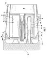
- Fig. 1 provides a simplified cross-section of a portion of a combustor, such as may be included in a gas turbine, according to one embodiment of the present invention.
- the combustor 10 may include one or more nozzles 12 radially arranged between a cap 14 and an end cover 16.
- the cap 14 and a liner 18 generally surround and defme a combustion chamber 20 located downstream from the nozzles 12.
- upstream and downstream refer to the relative location of components in a fluid pathway. For example, component A is upstream from component B if a fluid flows from component A to component B. Conversely, component B is downstream from component A if component B receives a fluid flow from component A.
- Each nozzle 12 may generally include a shroud 22 that circumferentially surrounds at least a portion of a center body 24 to defme an annular passage 26 between the shroud 22 and the center body 24.
- the center body 24 generally extends axially from the end cover 16 toward the cap 14 to provide fluid communication for fuel to flow from the end cover 16, through the center body 20, and into the combustion chamber 20.
- the shroud 22 may include a bellmouth opening 28 to enhance the radial distribution of the compressed working fluid flowing through the annular passage 26 between the shroud 22 and the center body 24.
- one or more vanes 30 extending radially between the center body 24 and the shroud 22 may impart a tangential swirl to the compressed working fluid to enhance mixing between the compressed working fluid and the fuel prior to combustion.
- a cap shield 32 may circumferentially surround the nozzles 12 between the cap 14 and the end cover 16, and a casing 34 may surround the liner 18 and cap shield 32 to defme an axis-symmetric annular passage 36 that circumferentially surrounds the combustion chamber 20 and nozzles 12.
- the compressed working fluid may flow through the annular passage 36 to provide impingement and/or convective cooling to the liner 18 and/or cap shield 32.
- the compressed working fluid When the compressed working fluid reaches the end cover 16, the compressed working fluid reverses direction to flow through the one or more nozzles 12 where it mixes with fuel before igniting in the combustion chamber 20 to produce combustion gases having a high temperature and pressure.
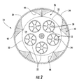
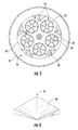
- Fig. 2 provides an downstream axial view of the combustor 10 shown in Fig. 1 taken along line A-A.
- the combustor 10 may include a plurality of baffles 40 disposed circumferentially around the cap shield 32.
- each baffle 40 extends radially inside the annular passage 36 between the casing 34 and the cap shield 32, while in other particular embodiments, a portion or all of each baffle 40 may extend radially inward from the cap shield 32.
- each baffle 40 may be circumferentially disposed between adjacent nozzles 12 and fixedly connected to at least one of the casing 34 or the cap shield 32.
- the baffles 40 divide and distribute the compressed working fluid flowing through the annular passage 36 to reduce pressure losses across the combustor 10 and/or reduce low flow regions in the vicinity of the nozzles 12. Specifically, the compressed working fluid flowing through the annular passage 36 is redirected, guided, or curved circumferentially and/or radially inward by the baffles 40 to more evenly distribute the compressed working fluid into the bellmouth opening 28 of each nozzle 12.
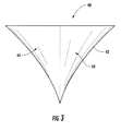
- Fig. 3 provides a perspective view of an exemplary baffle 40 shown in Figs. 1 and 2 according to one embodiment of the present invention.
- each baffle 40 may comprise one or more substantially triangular surfaces 42 and/or concave surfaces 44 to reduce the flow resistance, and thus the pressure drop, of the compressed working fluid flowing over the baffles 40.
- One of ordinary skill in the art can readily determine other suitable shapes and curvatures for the baffles 40 to complement the particular arrangement and geometry of the nozzles 12 radially arranged in the combustor 10, and the particular shape and/or curvature of the baffles 40 is not a limitation of the present invention unless specifically recited in the claims.
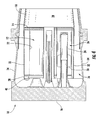
- Figs. 4 and 5 provides simplified cross-section and axial views of the combustor 10 according to a second embodiment of the present invention.
- the combustor 10 again includes one or more nozzles 12 radially arranged between the cap 14 and end cover 16 and the other general components as previously described with respect to the embodiment shown in Fig. 1 .
- the combustor 10 again includes the plurality of baffles 40 radially disposed around the cap shield 32, with each baffle 40 again circumferentially disposed between the adjacent nozzles 12. However, as shown most clearly in Fig. 5 , in this particular embodiment, each baffle 40 is radially disposed completely inward of the cap shield 32.
- the baffles 40 again divide and distribute the compressed working fluid into the bellmouth openings 28 of the adjacent nozzles to reduce pressure losses across the combustor 10 and/or reduce low flow regions in the vicinity of the nozzles 12.
- the compressed working fluid flowing through the annular passage 36 reverses direction as it reaches the end cover 16, and the baffles 40 redirect, guide, or curve the compressed working fluid circumferentially and/or radially inward to more evenly distribute the compressed working fluid into the bellmouth opening 28 of each nozzle 12.
- Fig. 6 provides a perspective view of an exemplary baffle 40 shown in Figs. 4 and 5 according to an alternate embodiment of the present invention.
- each baffle 40 may again comprise a substantially triangular surface 42 to allow each baffle 40 to fit circumferentially between adjacent nozzles 12.
- each baffle further includes a convex surface 46 to reduce the flow resistance, and thus the pressure drop, of the compressed working fluid flowing over the baffles 40 and into the adjacent nozzles 12.
- baffles 40 can readily determine other suitable shapes and curvatures for the baffles 40 to complement the particular arrangement and geometry of the nozzles 12 radially arranged in the combustor 10, and the particular shape and/or curvature of the baffles 40 is not a limitation of the present invention unless specifically recited in the claims.
- each nozzle 12 will receive a more uniform distribution of compressed working fluid, by volume and velocity, which in turn enhances the efficiency and flame holding margin for each nozzle 12.
Landscapes
- Engineering & Computer Science (AREA)
- Chemical & Material Sciences (AREA)
- Combustion & Propulsion (AREA)
- Mechanical Engineering (AREA)
- General Engineering & Computer Science (AREA)
- Gas Burners (AREA)
Applications Claiming Priority (1)
| Application Number | Priority Date | Filing Date | Title |
|---|---|---|---|
| US13/153,506 US20120305677A1 (en) | 2011-06-06 | 2011-06-06 | System for conditioning flow through a nozzle |
Publications (1)
| Publication Number | Publication Date |
|---|---|
| EP2532957A2 true EP2532957A2 (fr) | 2012-12-12 |
Family
ID=46172717
Family Applications (1)
| Application Number | Title | Priority Date | Filing Date |
|---|---|---|---|
| EP12169988A Withdrawn EP2532957A2 (fr) | 2011-06-06 | 2012-05-30 | Système de conditionnement d'écoulement à travers une buse |
Country Status (3)
| Country | Link |
|---|---|
| US (1) | US20120305677A1 (fr) |
| EP (1) | EP2532957A2 (fr) |
| CN (1) | CN102818289A (fr) |
Family Cites Families (1)
| Publication number | Priority date | Publication date | Assignee | Title |
|---|---|---|---|---|
| JP3364169B2 (ja) * | 1999-06-09 | 2003-01-08 | 三菱重工業株式会社 | ガスタービン及びその燃焼器 |
-
2011
- 2011-06-06 US US13/153,506 patent/US20120305677A1/en not_active Abandoned
-
2012
- 2012-05-30 EP EP12169988A patent/EP2532957A2/fr not_active Withdrawn
- 2012-06-06 CN CN2012101944641A patent/CN102818289A/zh active Pending
Non-Patent Citations (1)
| Title |
|---|
| None |
Also Published As
| Publication number | Publication date |
|---|---|
| CN102818289A (zh) | 2012-12-12 |
| US20120305677A1 (en) | 2012-12-06 |
Similar Documents
| Publication | Publication Date | Title |
|---|---|---|
| US8904798B2 (en) | Combustor | |
| EP3171088B1 (fr) | Ensemble injecteur de carburant à faisceau tubulaire ayant une capacité de combustible liquide | |
| EP2629017B1 (fr) | Chambre de combustion | |
| EP2613002B1 (fr) | Procédés et systèmes de refroidissement d'une buse de transition | |
| EP2584266B1 (fr) | Chambre de combustion et procédé de conditionnement d'écoulement à travers une chambre de combustion | |
| CN203880748U (zh) | 燃烧器 | |
| EP2578939B1 (fr) | Chambre de combustion et procédé pour fournir du débit dans une chambre de combustion | |
| US9366437B2 (en) | System for reducing flame holding within a combustor | |
| EP2208933B1 (fr) | Ensemble de chambre de combustion et dôme pour moteur de turbine | |
| EP2899368B1 (fr) | Agencement de turbine à gaz avec rapports entre le nombre d'aubes de diffuseur et le nombre d'ensembles d'injection de carburant | |
| EP3315866B1 (fr) | Ensemble de chambre de combustion comportant un composant auxiliaire monté | |
| US9528440B2 (en) | Gas turbine exhaust diffuser strut fairing having flow manifold and suction side openings | |
| US8579211B2 (en) | System and method for enhancing flow in a nozzle | |
| US10815789B2 (en) | Impingement holes for a turbine engine component | |
| EP2679775A1 (fr) | Conduit de transition pour turbine à gaz | |
| EP3015650A1 (fr) | Composant d' une turbine à gaz comportant un canal convergent-divergent | |
| EP3220051A1 (fr) | Injecteur de carburant à faisceau tubulaire avec amortissement de vibrations | |
| EP2511607A2 (fr) | Buse de chambre de combustion et procédé pour fournir du carburant à une chambre de combustion | |
| CN108386869A (zh) | 用于燃气涡轮发动机的燃烧器组件 | |
| EP2578940A2 (fr) | Chambre de combustion et procédé pour fournir du débit dans une chambre de combustion | |
| CN105371277A (zh) | 燃烧器罩盖组件 | |
| US8640974B2 (en) | System and method for cooling a nozzle | |
| EP3220049A1 (fr) | Chambre de combustion de turbine à gaz ayant des aubes de guidage de refroidissement de chemise de combustion | |
| EP3461995B1 (fr) | Aube de turbine à gaz | |
| EP2532964A2 (fr) | Système de conditionnement de l'écoulement à travers une chambre de combustion |
Legal Events
| Date | Code | Title | Description |
|---|---|---|---|
| PUAI | Public reference made under article 153(3) epc to a published international application that has entered the european phase |
Free format text: ORIGINAL CODE: 0009012 |
|
| AK | Designated contracting states |
Kind code of ref document: A2 Designated state(s): AL AT BE BG CH CY CZ DE DK EE ES FI FR GB GR HR HU IE IS IT LI LT LU LV MC MK MT NL NO PL PT RO RS SE SI SK SM TR |
|
| AX | Request for extension of the european patent |
Extension state: BA ME |
|
| STAA | Information on the status of an ep patent application or granted ep patent |
Free format text: STATUS: THE APPLICATION IS DEEMED TO BE WITHDRAWN |
|
| 18D | Application deemed to be withdrawn |
Effective date: 20141202 |