EP2532959A2 - Système et procédé d'alimentation en combustible - Google Patents
Système et procédé d'alimentation en combustible Download PDFInfo
- Publication number
- EP2532959A2 EP2532959A2 EP20120170527 EP12170527A EP2532959A2 EP 2532959 A2 EP2532959 A2 EP 2532959A2 EP 20120170527 EP20120170527 EP 20120170527 EP 12170527 A EP12170527 A EP 12170527A EP 2532959 A2 EP2532959 A2 EP 2532959A2
- Authority
- EP
- European Patent Office
- Prior art keywords
- fuel
- manifold
- water
- turbulator
- distributor
- Prior art date
- Legal status (The legal status is an assumption and is not a legal conclusion. Google has not performed a legal analysis and makes no representation as to the accuracy of the status listed.)
- Granted
Links
Images



Classifications
-
- F—MECHANICAL ENGINEERING; LIGHTING; HEATING; WEAPONS; BLASTING
- F23—COMBUSTION APPARATUS; COMBUSTION PROCESSES
- F23K—FEEDING FUEL TO COMBUSTION APPARATUS
- F23K5/00—Feeding or distributing other fuel to combustion apparatus
- F23K5/02—Liquid fuel
- F23K5/08—Preparation of fuel
- F23K5/10—Mixing with other fluids
- F23K5/12—Preparing emulsions
-
- F—MECHANICAL ENGINEERING; LIGHTING; HEATING; WEAPONS; BLASTING
- F02—COMBUSTION ENGINES; HOT-GAS OR COMBUSTION-PRODUCT ENGINE PLANTS
- F02C—GAS-TURBINE PLANTS; AIR INTAKES FOR JET-PROPULSION PLANTS; CONTROLLING FUEL SUPPLY IN AIR-BREATHING JET-PROPULSION PLANTS
- F02C3/00—Gas-turbine plants characterised by the use of combustion products as the working fluid
- F02C3/20—Gas-turbine plants characterised by the use of combustion products as the working fluid using a special fuel, oxidant, or dilution fluid to generate the combustion products
- F02C3/30—Adding water, steam or other fluids for influencing combustion, e.g. to obtain cleaner exhaust gases
-
- F—MECHANICAL ENGINEERING; LIGHTING; HEATING; WEAPONS; BLASTING
- F02—COMBUSTION ENGINES; HOT-GAS OR COMBUSTION-PRODUCT ENGINE PLANTS
- F02C—GAS-TURBINE PLANTS; AIR INTAKES FOR JET-PROPULSION PLANTS; CONTROLLING FUEL SUPPLY IN AIR-BREATHING JET-PROPULSION PLANTS
- F02C7/00—Features, components parts, details or accessories, not provided for in, or of interest apart form groups F02C1/00 - F02C6/00; Air intakes for jet-propulsion plants
- F02C7/22—Fuel supply systems
- F02C7/222—Fuel flow conduits, e.g. manifolds
-
- F—MECHANICAL ENGINEERING; LIGHTING; HEATING; WEAPONS; BLASTING
- F05—INDEXING SCHEMES RELATING TO ENGINES OR PUMPS IN VARIOUS SUBCLASSES OF CLASSES F01-F04
- F05D—INDEXING SCHEME FOR ASPECTS RELATING TO NON-POSITIVE-DISPLACEMENT MACHINES OR ENGINES, GAS-TURBINES OR JET-PROPULSION PLANTS
- F05D2240/00—Components
- F05D2240/10—Stators
- F05D2240/12—Fluid guiding means, e.g. vanes
- F05D2240/126—Baffles or ribs
-
- F—MECHANICAL ENGINEERING; LIGHTING; HEATING; WEAPONS; BLASTING
- F05—INDEXING SCHEMES RELATING TO ENGINES OR PUMPS IN VARIOUS SUBCLASSES OF CLASSES F01-F04
- F05D—INDEXING SCHEME FOR ASPECTS RELATING TO NON-POSITIVE-DISPLACEMENT MACHINES OR ENGINES, GAS-TURBINES OR JET-PROPULSION PLANTS
- F05D2240/00—Components
- F05D2240/10—Stators
- F05D2240/12—Fluid guiding means, e.g. vanes
- F05D2240/127—Vortex generators, turbulators, or the like, for mixing
-
- Y—GENERAL TAGGING OF NEW TECHNOLOGICAL DEVELOPMENTS; GENERAL TAGGING OF CROSS-SECTIONAL TECHNOLOGIES SPANNING OVER SEVERAL SECTIONS OF THE IPC; TECHNICAL SUBJECTS COVERED BY FORMER USPC CROSS-REFERENCE ART COLLECTIONS [XRACs] AND DIGESTS
- Y10—TECHNICAL SUBJECTS COVERED BY FORMER USPC
- Y10T—TECHNICAL SUBJECTS COVERED BY FORMER US CLASSIFICATION
- Y10T137/00—Fluid handling
- Y10T137/0318—Processes
-
- Y—GENERAL TAGGING OF NEW TECHNOLOGICAL DEVELOPMENTS; GENERAL TAGGING OF CROSS-SECTIONAL TECHNOLOGIES SPANNING OVER SEVERAL SECTIONS OF THE IPC; TECHNICAL SUBJECTS COVERED BY FORMER USPC CROSS-REFERENCE ART COLLECTIONS [XRACs] AND DIGESTS
- Y10—TECHNICAL SUBJECTS COVERED BY FORMER USPC
- Y10T—TECHNICAL SUBJECTS COVERED BY FORMER US CLASSIFICATION
- Y10T137/00—Fluid handling
- Y10T137/8593—Systems
- Y10T137/85978—With pump
Definitions
- the present invention generally involves a system and method for supplying fuel.
- the system and method may include a turbulator and/or a distributor to mix and distribute an emulsion fuel prior to combustion.
- Combustors are commonly used in industrial and commercial operations to ignite fuel to produce combustion gases having a high temperature and pressure.
- a typical commercial gas turbine used to generate electrical power may include an axial compressor at the front, one or more combustors around the middle, and a turbine at the rear.
- Ambient air may be supplied to the compressor, and rotating blades and stationary vanes in the compressor progressively impart kinetic energy to the working fluid (air) to produce a compressed working fluid at a highly energized state.
- the compressed working fluid exits the compressor and flows through one or more nozzles in each combustor where the compressed working fluid mixes with fuel and ignites to generate combustion gases having a high temperature and pressure.
- the combustion gases expand in the turbine to produce work. For example, expansion of the combustion gases in the turbine may rotate a shaft connected to a generator to produce electricity.
- the fuel supplied to the combustor may be a liquid fuel, a gaseous fuel, or a combination of liquid and gaseous fuels. If the liquid and/or gaseous fuel is not evenly mixed with the compressed working fluid prior to combustion, localized hot spots may form in the combustor. The localized hot spots may increase the production of nitrous oxides in the fuel rich regions, while the fuel lean regions may increase the production of carbon monoxide and unburned hydrocarbons, all of which are undesirable exhaust emissions. In addition, the fuel rich regions may increase the chance for the flame in the combustor to flash back into the nozzles and/or become attached inside the nozzles which may damage the nozzles. Although flame flash back and flame holding may occur with any fuel, they occur more readily with high reactive fuels, such as hydrogen, that have a higher burning rate and a wider flammability range.
- water may be added to the fuel to produce an emulsion fuel that enhances combustion efficiency and reduces the peak flame temperature, and thus nitrous oxide production, in the combustor.
- the emulsion fuel inherently tends to quickly separate back into the constituent elements of fuel and water, creating variations in the flow rate and fuel-water content of emulsion fuel supplied to each nozzle. This in turn may create flame instabilities between nozzles, decrease the overall efficiency of the combustor, and increase undesirable emissions. Therefore, an improved system and method for supplying fuel to a combustor would be useful.
- the present invention resides in a system for supplying emulsion fuel.
- the system includes a fuel manifold, a water manifold, and a fluid junction between the fuel manifold and the water manifold.
- a turbulator downstream from the fluid junction receives a fluid flow from the fluid junction.
- the present invention further resides in a system for supplying fuel that includes an emulsion fluid manifold and means for dividing a fluid flow from the emulsion fluid manifold substantially equally.
- the present invention resides in a method for supplying fuel that includes flowing fuel through a fuel manifold, flowing water through a water manifold, and combining a portion of the water from the water manifold with the fuel from the fuel manifold to create emulsion fuel.
- the method further includes flowing the emulsion fuel through a turbulator.
- Various embodiments of the present invention provide a system and method for supplying an emulsion fuel to a combustor.
- fuel and water are mixed, and the mixture is directed through a turbulator to further mix the emulsion fuel.
- a distributor or other means may be used to deliver and/or divide the emulsion fuel in substantially equal amounts to each nozzle in the combustor.
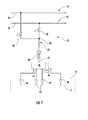
- Fig. 1 provides a simplified diagram of a system 10 for supplying an emulsion fuel 12 to a combustor 14 according to one embodiment of the present invention.
- the system 10 generally includes a fuel manifold 16, a water manifold 18, and a fluid junction 20 between the fuel and water manifolds 16, 18 that produces an emulsion fluid manifold 22.
- the term "manifold” includes any pipe or chamber having multiple apertures for making connections.
- Possible fuels supplied through the fuel manifold 16 may include, for example, blast furnace gas, coke oven gas, natural gas, methane, vaporized liquefied natural gas (LNG), propane, hydrogen, and combinations thereof.
- LNG vaporized liquefied natural gas
- the water manifold 16 may contain water, steam, or similar diluents suitable for mixing with the fuel to form the emulsion fuel 12.
- Each manifold 16, 18, 22 may comprise a combination of suitable piping and valves that facilitate the fluid communication, transport, and isolation of the desired fluids.
- fuel piping 24 and water piping 26 may be used to transport the fuel and water proximate to the combustor 14, and one or more throttle valves 28 may be used to regulate the amount of fuel and/or water supplied to the emulsion fluid manifold 22 and/or combustor 14.
- the fluid junction 20 may comprise any fluid connection between the fuel manifold 16 and the water manifold 18 that allows the fuel and water to mix to form the emulsion fuel 12.
- the system 10 may further include a turbulator 30 downstream from the fluid junction 20 and/or inside the emulsion fluid manifold 22.
- a turbulator 30 downstream from the fluid junction 20 and/or inside the emulsion fluid manifold 22.
- upstream and downstream refer to the relative location of components in a fluid pathway.
- component A is upstream from component B if a fluid flows from component A to component B.
- component B is downstream from component A if component B receives a fluid flow from component A.
- Figs. 2 and 3 provide perspective views of exemplary turbulators 30 within the scope of various embodiments of the present invention.
- the turbulator 30 may comprise a series of twisted wires, plates, or baffles 32.
- the turbulator 30 may comprise a screen 34 having a plurality of staggered apertures 36.
- the screen 34 may comprise a conical surface, a flat surface, or any other geometric shape.
- the turbulator 30 may comprise virtually any tortuous or turbulent pathway over which the emulsion fuel 12 may flow. In each embodiment, the turbulator 30 thus enhances mixing between the fuel and water in the emulsion fluid manifold 22 to prevent the constituent elements from separating before reaching the combustor 14.
- the system 10 may further include a distributor 40 downstream from the turbulator 30 and/or emulsion fluid manifold 22.
- the distributor 40 generally comprises an inlet 42 and a plurality of outlets 44, with each outlet 44 in fluid communication with a separate nozzle 46 in the combustor 14. In this manner, the distributor 40 delivers the emulsion fuel 12 into separate pathways for each nozzle 46.
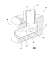
- Fig. 4 provides a perspective cross-section view of a first embodiment of a distributor 40 within the scope of the present invention.
- the distributor 40 may further comprise a body 48 that defines a cavity 50 having a bottom surface 52.
- Each outlet 44 may connect to the cavity 50 at or flush with the bottom surface 52 to reduce or prevent low flow or recirculation regions from forming inside the cavity 50.
- the distributor 40 facilitates the ability to change fuels and/or fuel-water ratios in the emulsion fuel 12 without retaining pockets of the old fuel and/or emulsion fuel 12.
- the distributor 40 may further include means for dividing the fluid flow from the turbulator 30 and/or emulsion fluid manifold 22 substantially equally.
- the means may comprise a projection 54 that extends from the body 48 into a center portion of the cavity 50.
- the projection 54 may comprise a cylindrical, conical, spherical, pyramidal, or other geometric shape suitable for dividing a fluid flow. In this manner, the emulsion fuel 12 entering the inlet 42 is divided into substantially equal amounts before exiting the distributor 40 through each outlet 44 and flowing to the respective nozzles 46.
- Fig. 5 provides a perspective cross-section view of a second embodiment of the distributor 40 within the scope of the present invention.
- the distributor 40 again comprises the inlet 42, outlets 44, body 48, cavity 50, and bottom surface 52 as previously described with respect to the embodiment shown in Fig. 4 .
- the means for dividing the fluid flow from the turbulator 30 and/or emulsion fluid manifold 22 substantially equally comprises an insert 56 inside the body 48 that defines a Nagel point 58 inside the cavity 50.
- the insert 56 may be defined by the body 48, as shown in Fig. 5 , or may constitute a separate component inserted into the body 48, as shown in Fig. 6 .
- the insert 56 generally defines a triangular opening having curved sides 60, and vertices 62 of the triangular opening generally coincide with the outlets 44 in the distributor 40.
- the inlet 42 is aligned generally coincident with an axis 64 that extends through the Nagel point 58 defined by the insert 56 so that the emulsion fuel 12 entering the inlet 42 is divided into substantially equal amounts before exiting the distributor 40 through the outlets 44 and flowing to the respective nozzles 46.
- the system 10 and components shown in Figs. 1-6 may also provide a method for supplying emulsion fuel 12 to the combustor 14.
- the method generally includes flowing fuel through the fuel manifold 24, flowing water through the water manifold 26, and combining a portion of the water from the water manifold 26 with the fuel from the fuel manifold 24 to create emulsion fuel 12.
- the method further includes flowing the emulsion fuel 12 through the turbulator 30.
- the method may also include dividing the flow of emulsion fuel 12 substantially equally, distributing the emulsion fuel 12 to the plurality of nozzles 46, and/or dividing the flow of emulsion fuel 12 substantially equally inside the distributor 40.
- the system 10 and method shown in Figs. 1-6 enhance the quality of the emulsion fuel 12 supplied to the combustor 14, thereby improving the combustion efficiency, promoting flame stability between nozzles 46, and reducing undesirable emissions.
Landscapes
- Engineering & Computer Science (AREA)
- Chemical & Material Sciences (AREA)
- Combustion & Propulsion (AREA)
- Mechanical Engineering (AREA)
- General Engineering & Computer Science (AREA)
- Liquid Carbonaceous Fuels (AREA)
- Spray-Type Burners (AREA)
- Feeding And Controlling Fuel (AREA)
Applications Claiming Priority (1)
| Application Number | Priority Date | Filing Date | Title |
|---|---|---|---|
| US13/153,585 US9719681B2 (en) | 2011-06-06 | 2011-06-06 | System and method for supplying fuel |
Publications (3)
| Publication Number | Publication Date |
|---|---|
| EP2532959A2 true EP2532959A2 (fr) | 2012-12-12 |
| EP2532959A3 EP2532959A3 (fr) | 2017-12-13 |
| EP2532959B1 EP2532959B1 (fr) | 2022-07-27 |
Family
ID=46201459
Family Applications (1)
| Application Number | Title | Priority Date | Filing Date |
|---|---|---|---|
| EP12170527.1A Active EP2532959B1 (fr) | 2011-06-06 | 2012-06-01 | Système et procédé d'alimentation en combustible |
Country Status (3)
| Country | Link |
|---|---|
| US (1) | US9719681B2 (fr) |
| EP (1) | EP2532959B1 (fr) |
| CN (1) | CN102818278A (fr) |
Cited By (4)
| Publication number | Priority date | Publication date | Assignee | Title |
|---|---|---|---|---|
| ITVR20130082A1 (it) * | 2013-04-05 | 2014-10-06 | Fuber Ltd | Dispositivo e metodo per la realizzazione di emulsioni di acqua in olio combustibile o in una miscela contenente principalmente olio combustibile |
| FR3072126A1 (fr) * | 2017-10-10 | 2019-04-12 | Ge Energy Products France Snc | Systemes d'alimentation en combustible liquide d'un systeme de combustion, notamment d'une turbine a gaz, comprenant un dispositif de generation d'une emulsion et de repartition du debit d'emulsion |
| US11015126B2 (en) | 2016-12-30 | 2021-05-25 | Eme International Limited | Apparatus and method for producing biomass derived liquid, bio-fuel and bio-material |
| US11084004B2 (en) | 2014-11-10 | 2021-08-10 | Eme International Lux S.A. | Device for mixing water and diesel oil, apparatus and process for producing a water/diesel oil micro-emulsion |
Families Citing this family (7)
| Publication number | Priority date | Publication date | Assignee | Title |
|---|---|---|---|---|
| US20130283810A1 (en) * | 2012-04-30 | 2013-10-31 | General Electric Company | Combustion nozzle and a related method thereof |
| JP6049530B2 (ja) * | 2013-04-22 | 2016-12-21 | 大阪瓦斯株式会社 | 混合気供給システム及び混合気供給システムに用いる混合気供給装置 |
| JP2017524094A (ja) | 2014-07-02 | 2017-08-24 | ヌオーヴォ ピニォーネ ソチエタ レスポンサビリタ リミタータNuovo Pignone S.R.L. | 燃料分配装置、ガスタービンエンジン、および取り付け方法 |
| US20160341429A1 (en) * | 2015-05-20 | 2016-11-24 | General Electric Company | Gas turbine engine liquid fuel supply system and method |
| US10746101B2 (en) | 2017-06-13 | 2020-08-18 | General Electric Company | Annular fuel manifold with a deflector |
| CN113969837B (zh) * | 2020-07-24 | 2026-01-23 | 通用电气技术有限公司 | 改善的燃料分配歧管 |
| EP4134531B1 (fr) | 2021-08-12 | 2024-11-06 | General Electric Technology GmbH | Moteur à turbine à gaz avec émulsion eau-carburant et méthode |
Family Cites Families (20)
| Publication number | Priority date | Publication date | Assignee | Title |
|---|---|---|---|---|
| US3262466A (en) | 1963-07-29 | 1966-07-26 | Moore Products Co | Flow control apparatus |
| GB1219270A (en) | 1967-12-28 | 1971-01-13 | Raymond Victor Thompson | Improvements in or relating to fluid relays |
| US4214435A (en) | 1977-07-25 | 1980-07-29 | General Electric Company | Method for reducing nitrous oxide emissions from a gas turbine engine |
| US4259021A (en) | 1978-04-19 | 1981-03-31 | Paul R. Goudy, Jr. | Fluid mixing apparatus and method |
| US4413935A (en) * | 1981-06-29 | 1983-11-08 | Combustion Engineering, Inc. | Flow splitter for dividing a stream of pulverulent material into multiple streams |
| US4824614A (en) * | 1987-04-09 | 1989-04-25 | Santa Fe Energy Company | Device for uniformly distributing a two-phase fluid |
| GB2233572B (en) | 1989-07-10 | 1994-03-23 | Neptune Orient Lines Limited | Method and apparatus for producing layer-in-oil emulsions |
| US5170727A (en) | 1991-03-29 | 1992-12-15 | Union Carbide Chemicals & Plastics Technology Corporation | Supercritical fluids as diluents in combustion of liquid fuels and waste materials |
| US5175994A (en) * | 1991-05-03 | 1993-01-05 | United Technologies Corporation | Combustion section supply system having fuel and water injection for a rotary machine |
| US5251662A (en) * | 1992-10-19 | 1993-10-12 | Texaco Inc. | Device to equally distribute the vapor and liquid phases during wet steam flow through branch tee junctions |
| US5628184A (en) * | 1993-02-03 | 1997-05-13 | Santos; Rolando R. | Apparatus for reducing the production of NOx in a gas turbine |
| US5670093A (en) * | 1996-02-14 | 1997-09-23 | Atlantic Richfield Company | Fluid distribution system and method utilizing a radial splitter |
| JP3732280B2 (ja) | 1996-08-07 | 2006-01-05 | 阪神内燃機工業株式会社 | 燃料油処理装置 |
| US6311472B1 (en) * | 1999-04-12 | 2001-11-06 | Helios Energy Technologies, Inc. | Method and means of fluid supply for combustion systems |
| US6360776B1 (en) * | 2000-11-01 | 2002-03-26 | Rolls-Royce Corporation | Apparatus for premixing in a gas turbine engine |
| US20030027089A1 (en) | 2001-02-19 | 2003-02-06 | Martin Mueller | Method and device for reducing the acidic pollutant emissions of industrial installations |
| US7810309B2 (en) * | 2002-12-06 | 2010-10-12 | Hamilton Sundstrand | Fuel system utilizing dual mixing pump |
| US8028529B2 (en) * | 2006-05-04 | 2011-10-04 | General Electric Company | Low emissions gas turbine combustor |
| WO2009054378A1 (fr) | 2007-10-22 | 2009-04-30 | Mg Grow Up Corp. | Fioul reformé, processus de production de celui-ci et appareil associé |
| US7942162B2 (en) * | 2008-01-14 | 2011-05-17 | National Tank Company | Tee flow splitter |
-
2011
- 2011-06-06 US US13/153,585 patent/US9719681B2/en active Active
-
2012
- 2012-06-01 EP EP12170527.1A patent/EP2532959B1/fr active Active
- 2012-06-06 CN CN2012101944603A patent/CN102818278A/zh active Pending
Non-Patent Citations (1)
| Title |
|---|
| None |
Cited By (6)
| Publication number | Priority date | Publication date | Assignee | Title |
|---|---|---|---|---|
| ITVR20130082A1 (it) * | 2013-04-05 | 2014-10-06 | Fuber Ltd | Dispositivo e metodo per la realizzazione di emulsioni di acqua in olio combustibile o in una miscela contenente principalmente olio combustibile |
| WO2014162281A3 (fr) * | 2013-04-05 | 2014-12-31 | Fuber Limited | Dispositif et procédé de fabrication d'émulsions d'eau dans du mazout ou dans un mélange contenant principalement du mazout |
| US11084004B2 (en) | 2014-11-10 | 2021-08-10 | Eme International Lux S.A. | Device for mixing water and diesel oil, apparatus and process for producing a water/diesel oil micro-emulsion |
| US11015126B2 (en) | 2016-12-30 | 2021-05-25 | Eme International Limited | Apparatus and method for producing biomass derived liquid, bio-fuel and bio-material |
| FR3072126A1 (fr) * | 2017-10-10 | 2019-04-12 | Ge Energy Products France Snc | Systemes d'alimentation en combustible liquide d'un systeme de combustion, notamment d'une turbine a gaz, comprenant un dispositif de generation d'une emulsion et de repartition du debit d'emulsion |
| US11434817B2 (en) | 2017-10-10 | 2022-09-06 | General Electric Company | Systems for supplying liquid fuel emulsion to a combustion system of a gas turbine |
Also Published As
| Publication number | Publication date |
|---|---|
| EP2532959A3 (fr) | 2017-12-13 |
| US20120305086A1 (en) | 2012-12-06 |
| US9719681B2 (en) | 2017-08-01 |
| CN102818278A (zh) | 2012-12-12 |
| EP2532959B1 (fr) | 2022-07-27 |
Similar Documents
| Publication | Publication Date | Title |
|---|---|---|
| US9719681B2 (en) | System and method for supplying fuel | |
| EP2657483B1 (fr) | Système permettant de fournir du carburant à une chambre de combustion | |
| EP2657611B1 (fr) | Système permettant de fournir du carburant à une chambre de combustion | |
| CN105637206B (zh) | 用于排放来自燃气涡轮发动机的燃烧气体的系统和方法 | |
| CN103196158B (zh) | 燃烧器和用于在燃烧器中分配燃料的方法 | |
| US8904798B2 (en) | Combustor | |
| CN103307636B (zh) | 用于将工作流体供应到燃烧器的系统 | |
| US9593851B2 (en) | Combustor and method of supplying fuel to the combustor | |
| CN102022728B (zh) | 用于燃烧器的径向入口导叶 | |
| CN103307635A (zh) | 用于将工作流体供应到燃烧器的系统 | |
| CN102927592A (zh) | 涡轮机燃烧器组件 | |
| CN107548433A (zh) | 用于具有排气再循环的燃气涡轮发动机中高体积氧化剂流的系统和方法 | |
| US11041623B2 (en) | Gas turbine combustor with heat exchanger between rich combustion zone and secondary combustion zone | |
| EP3376109A1 (fr) | Buse à combustible bicombustible avec une extrémité injectant du combustible liquide | |
| JP2013253769A (ja) | 燃料予混合器を有する燃焼器アセンブリ | |
| WO2013125972A1 (fr) | Buse de chambre de combustion et procédé pour fournir du combustible à une chambre de combustion | |
| CN103423773A (zh) | 二次燃烧系统 | |
| EP3425281B1 (fr) | Buse pilote dotée de prémélange en ligne | |
| EP2592349A2 (fr) | Chambre de combustion et procédé pour fournir du carburant à une chambre de combustion | |
| CN102788369B (zh) | 适应性燃烧室燃料喷嘴 | |
| US20140061327A1 (en) | System and method for staging fuel to a combustor | |
| CN110476017A (zh) | 具有轴向分级燃料喷射的燃烧系统 | |
| CN101886554A (zh) | 交叉流导叶 | |
| JP2025183930A (ja) | 複数の燃料を配合するためのシステム及び方法 | |
| JP2025186171A (ja) | 複数の燃料を配合するためのシステム及び方法 |
Legal Events
| Date | Code | Title | Description |
|---|---|---|---|
| PUAI | Public reference made under article 153(3) epc to a published international application that has entered the european phase |
Free format text: ORIGINAL CODE: 0009012 |
|
| AK | Designated contracting states |
Kind code of ref document: A2 Designated state(s): AL AT BE BG CH CY CZ DE DK EE ES FI FR GB GR HR HU IE IS IT LI LT LU LV MC MK MT NL NO PL PT RO RS SE SI SK SM TR |
|
| AX | Request for extension of the european patent |
Extension state: BA ME |
|
| PUAL | Search report despatched |
Free format text: ORIGINAL CODE: 0009013 |
|
| AK | Designated contracting states |
Kind code of ref document: A3 Designated state(s): AL AT BE BG CH CY CZ DE DK EE ES FI FR GB GR HR HU IE IS IT LI LT LU LV MC MK MT NL NO PL PT RO RS SE SI SK SM TR |
|
| AX | Request for extension of the european patent |
Extension state: BA ME |
|
| RIC1 | Information provided on ipc code assigned before grant |
Ipc: F02C 7/22 20060101ALI20171109BHEP Ipc: F23K 5/12 20060101AFI20171109BHEP Ipc: F02C 3/30 20060101ALI20171109BHEP |
|
| STAA | Information on the status of an ep patent application or granted ep patent |
Free format text: STATUS: REQUEST FOR EXAMINATION WAS MADE |
|
| 17P | Request for examination filed |
Effective date: 20180613 |
|
| RBV | Designated contracting states (corrected) |
Designated state(s): AL AT BE BG CH CY CZ DE DK EE ES FI FR GB GR HR HU IE IS IT LI LT LU LV MC MK MT NL NO PL PT RO RS SE SI SK SM TR |
|
| STAA | Information on the status of an ep patent application or granted ep patent |
Free format text: STATUS: EXAMINATION IS IN PROGRESS |
|
| 17Q | First examination report despatched |
Effective date: 20200123 |
|
| GRAP | Despatch of communication of intention to grant a patent |
Free format text: ORIGINAL CODE: EPIDOSNIGR1 |
|
| STAA | Information on the status of an ep patent application or granted ep patent |
Free format text: STATUS: GRANT OF PATENT IS INTENDED |
|
| INTG | Intention to grant announced |
Effective date: 20220202 |
|
| GRAS | Grant fee paid |
Free format text: ORIGINAL CODE: EPIDOSNIGR3 |
|
| GRAA | (expected) grant |
Free format text: ORIGINAL CODE: 0009210 |
|
| STAA | Information on the status of an ep patent application or granted ep patent |
Free format text: STATUS: THE PATENT HAS BEEN GRANTED |
|
| AK | Designated contracting states |
Kind code of ref document: B1 Designated state(s): AL AT BE BG CH CY CZ DE DK EE ES FI FR GB GR HR HU IE IS IT LI LT LU LV MC MK MT NL NO PL PT RO RS SE SI SK SM TR |
|
| REG | Reference to a national code |
Ref country code: GB Ref legal event code: FG4D |
|
| REG | Reference to a national code |
Ref country code: CH Ref legal event code: EP |
|
| REG | Reference to a national code |
Ref country code: DE Ref legal event code: R096 Ref document number: 602012078522 Country of ref document: DE |
|
| REG | Reference to a national code |
Ref country code: AT Ref legal event code: REF Ref document number: 1507286 Country of ref document: AT Kind code of ref document: T Effective date: 20220815 |
|
| REG | Reference to a national code |
Ref country code: IE Ref legal event code: FG4D |
|
| REG | Reference to a national code |
Ref country code: LT Ref legal event code: MG9D |
|
| REG | Reference to a national code |
Ref country code: NL Ref legal event code: MP Effective date: 20220727 |
|
| PG25 | Lapsed in a contracting state [announced via postgrant information from national office to epo] |
Ref country code: SE Free format text: LAPSE BECAUSE OF FAILURE TO SUBMIT A TRANSLATION OF THE DESCRIPTION OR TO PAY THE FEE WITHIN THE PRESCRIBED TIME-LIMIT Effective date: 20220727 Ref country code: RS Free format text: LAPSE BECAUSE OF FAILURE TO SUBMIT A TRANSLATION OF THE DESCRIPTION OR TO PAY THE FEE WITHIN THE PRESCRIBED TIME-LIMIT Effective date: 20220727 Ref country code: PT Free format text: LAPSE BECAUSE OF FAILURE TO SUBMIT A TRANSLATION OF THE DESCRIPTION OR TO PAY THE FEE WITHIN THE PRESCRIBED TIME-LIMIT Effective date: 20221128 Ref country code: NO Free format text: LAPSE BECAUSE OF FAILURE TO SUBMIT A TRANSLATION OF THE DESCRIPTION OR TO PAY THE FEE WITHIN THE PRESCRIBED TIME-LIMIT Effective date: 20221027 Ref country code: NL Free format text: LAPSE BECAUSE OF FAILURE TO SUBMIT A TRANSLATION OF THE DESCRIPTION OR TO PAY THE FEE WITHIN THE PRESCRIBED TIME-LIMIT Effective date: 20220727 Ref country code: LV Free format text: LAPSE BECAUSE OF FAILURE TO SUBMIT A TRANSLATION OF THE DESCRIPTION OR TO PAY THE FEE WITHIN THE PRESCRIBED TIME-LIMIT Effective date: 20220727 Ref country code: LT Free format text: LAPSE BECAUSE OF FAILURE TO SUBMIT A TRANSLATION OF THE DESCRIPTION OR TO PAY THE FEE WITHIN THE PRESCRIBED TIME-LIMIT Effective date: 20220727 Ref country code: FI Free format text: LAPSE BECAUSE OF FAILURE TO SUBMIT A TRANSLATION OF THE DESCRIPTION OR TO PAY THE FEE WITHIN THE PRESCRIBED TIME-LIMIT Effective date: 20220727 Ref country code: ES Free format text: LAPSE BECAUSE OF FAILURE TO SUBMIT A TRANSLATION OF THE DESCRIPTION OR TO PAY THE FEE WITHIN THE PRESCRIBED TIME-LIMIT Effective date: 20220727 |
|
| REG | Reference to a national code |
Ref country code: AT Ref legal event code: MK05 Ref document number: 1507286 Country of ref document: AT Kind code of ref document: T Effective date: 20220727 |
|
| PG25 | Lapsed in a contracting state [announced via postgrant information from national office to epo] |
Ref country code: PL Free format text: LAPSE BECAUSE OF FAILURE TO SUBMIT A TRANSLATION OF THE DESCRIPTION OR TO PAY THE FEE WITHIN THE PRESCRIBED TIME-LIMIT Effective date: 20220727 Ref country code: IS Free format text: LAPSE BECAUSE OF FAILURE TO SUBMIT A TRANSLATION OF THE DESCRIPTION OR TO PAY THE FEE WITHIN THE PRESCRIBED TIME-LIMIT Effective date: 20221127 Ref country code: HR Free format text: LAPSE BECAUSE OF FAILURE TO SUBMIT A TRANSLATION OF THE DESCRIPTION OR TO PAY THE FEE WITHIN THE PRESCRIBED TIME-LIMIT Effective date: 20220727 Ref country code: GR Free format text: LAPSE BECAUSE OF FAILURE TO SUBMIT A TRANSLATION OF THE DESCRIPTION OR TO PAY THE FEE WITHIN THE PRESCRIBED TIME-LIMIT Effective date: 20221028 |
|
| PG25 | Lapsed in a contracting state [announced via postgrant information from national office to epo] |
Ref country code: SM Free format text: LAPSE BECAUSE OF FAILURE TO SUBMIT A TRANSLATION OF THE DESCRIPTION OR TO PAY THE FEE WITHIN THE PRESCRIBED TIME-LIMIT Effective date: 20220727 Ref country code: RO Free format text: LAPSE BECAUSE OF FAILURE TO SUBMIT A TRANSLATION OF THE DESCRIPTION OR TO PAY THE FEE WITHIN THE PRESCRIBED TIME-LIMIT Effective date: 20220727 Ref country code: DK Free format text: LAPSE BECAUSE OF FAILURE TO SUBMIT A TRANSLATION OF THE DESCRIPTION OR TO PAY THE FEE WITHIN THE PRESCRIBED TIME-LIMIT Effective date: 20220727 Ref country code: CZ Free format text: LAPSE BECAUSE OF FAILURE TO SUBMIT A TRANSLATION OF THE DESCRIPTION OR TO PAY THE FEE WITHIN THE PRESCRIBED TIME-LIMIT Effective date: 20220727 Ref country code: AT Free format text: LAPSE BECAUSE OF FAILURE TO SUBMIT A TRANSLATION OF THE DESCRIPTION OR TO PAY THE FEE WITHIN THE PRESCRIBED TIME-LIMIT Effective date: 20220727 |
|
| REG | Reference to a national code |
Ref country code: DE Ref legal event code: R097 Ref document number: 602012078522 Country of ref document: DE |
|
| PG25 | Lapsed in a contracting state [announced via postgrant information from national office to epo] |
Ref country code: SK Free format text: LAPSE BECAUSE OF FAILURE TO SUBMIT A TRANSLATION OF THE DESCRIPTION OR TO PAY THE FEE WITHIN THE PRESCRIBED TIME-LIMIT Effective date: 20220727 Ref country code: EE Free format text: LAPSE BECAUSE OF FAILURE TO SUBMIT A TRANSLATION OF THE DESCRIPTION OR TO PAY THE FEE WITHIN THE PRESCRIBED TIME-LIMIT Effective date: 20220727 |
|
| PLBE | No opposition filed within time limit |
Free format text: ORIGINAL CODE: 0009261 |
|
| STAA | Information on the status of an ep patent application or granted ep patent |
Free format text: STATUS: NO OPPOSITION FILED WITHIN TIME LIMIT |
|
| PG25 | Lapsed in a contracting state [announced via postgrant information from national office to epo] |
Ref country code: AL Free format text: LAPSE BECAUSE OF FAILURE TO SUBMIT A TRANSLATION OF THE DESCRIPTION OR TO PAY THE FEE WITHIN THE PRESCRIBED TIME-LIMIT Effective date: 20220727 |
|
| 26N | No opposition filed |
Effective date: 20230502 |
|
| PG25 | Lapsed in a contracting state [announced via postgrant information from national office to epo] |
Ref country code: SI Free format text: LAPSE BECAUSE OF FAILURE TO SUBMIT A TRANSLATION OF THE DESCRIPTION OR TO PAY THE FEE WITHIN THE PRESCRIBED TIME-LIMIT Effective date: 20220727 |
|
| REG | Reference to a national code |
Ref country code: DE Ref legal event code: R081 Ref document number: 602012078522 Country of ref document: DE Owner name: GENERAL ELECTRIC TECHNOLOGY GMBH, CH Free format text: FORMER OWNER: GENERAL ELECTRIC COMPANY, SCHENECTADY, NY, US |
|
| PG25 | Lapsed in a contracting state [announced via postgrant information from national office to epo] |
Ref country code: MC Free format text: LAPSE BECAUSE OF FAILURE TO SUBMIT A TRANSLATION OF THE DESCRIPTION OR TO PAY THE FEE WITHIN THE PRESCRIBED TIME-LIMIT Effective date: 20220727 |
|
| PG25 | Lapsed in a contracting state [announced via postgrant information from national office to epo] |
Ref country code: MC Free format text: LAPSE BECAUSE OF FAILURE TO SUBMIT A TRANSLATION OF THE DESCRIPTION OR TO PAY THE FEE WITHIN THE PRESCRIBED TIME-LIMIT Effective date: 20220727 |
|
| REG | Reference to a national code |
Ref country code: CH Ref legal event code: PL |
|
| REG | Reference to a national code |
Ref country code: BE Ref legal event code: MM Effective date: 20230630 |
|
| GBPC | Gb: european patent ceased through non-payment of renewal fee |
Effective date: 20230601 |
|
| PG25 | Lapsed in a contracting state [announced via postgrant information from national office to epo] |
Ref country code: LU Free format text: LAPSE BECAUSE OF NON-PAYMENT OF DUE FEES Effective date: 20230601 |
|
| REG | Reference to a national code |
Ref country code: IE Ref legal event code: MM4A |
|
| PG25 | Lapsed in a contracting state [announced via postgrant information from national office to epo] |
Ref country code: LU Free format text: LAPSE BECAUSE OF NON-PAYMENT OF DUE FEES Effective date: 20230601 |
|
| PG25 | Lapsed in a contracting state [announced via postgrant information from national office to epo] |
Ref country code: IE Free format text: LAPSE BECAUSE OF NON-PAYMENT OF DUE FEES Effective date: 20230601 |
|
| PG25 | Lapsed in a contracting state [announced via postgrant information from national office to epo] |
Ref country code: IE Free format text: LAPSE BECAUSE OF NON-PAYMENT OF DUE FEES Effective date: 20230601 Ref country code: GB Free format text: LAPSE BECAUSE OF NON-PAYMENT OF DUE FEES Effective date: 20230601 Ref country code: CH Free format text: LAPSE BECAUSE OF NON-PAYMENT OF DUE FEES Effective date: 20230630 |
|
| PG25 | Lapsed in a contracting state [announced via postgrant information from national office to epo] |
Ref country code: IT Free format text: LAPSE BECAUSE OF FAILURE TO SUBMIT A TRANSLATION OF THE DESCRIPTION OR TO PAY THE FEE WITHIN THE PRESCRIBED TIME-LIMIT Effective date: 20220727 Ref country code: FR Free format text: LAPSE BECAUSE OF NON-PAYMENT OF DUE FEES Effective date: 20230630 Ref country code: BE Free format text: LAPSE BECAUSE OF NON-PAYMENT OF DUE FEES Effective date: 20230630 |
|
| PG25 | Lapsed in a contracting state [announced via postgrant information from national office to epo] |
Ref country code: BG Free format text: LAPSE BECAUSE OF FAILURE TO SUBMIT A TRANSLATION OF THE DESCRIPTION OR TO PAY THE FEE WITHIN THE PRESCRIBED TIME-LIMIT Effective date: 20220727 |
|
| PG25 | Lapsed in a contracting state [announced via postgrant information from national office to epo] |
Ref country code: BG Free format text: LAPSE BECAUSE OF FAILURE TO SUBMIT A TRANSLATION OF THE DESCRIPTION OR TO PAY THE FEE WITHIN THE PRESCRIBED TIME-LIMIT Effective date: 20220727 |
|
| PGFP | Annual fee paid to national office [announced via postgrant information from national office to epo] |
Ref country code: DE Payment date: 20250520 Year of fee payment: 14 |
|
| PG25 | Lapsed in a contracting state [announced via postgrant information from national office to epo] |
Ref country code: CY Free format text: LAPSE BECAUSE OF FAILURE TO SUBMIT A TRANSLATION OF THE DESCRIPTION OR TO PAY THE FEE WITHIN THE PRESCRIBED TIME-LIMIT; INVALID AB INITIO Effective date: 20120601 |
|
| PG25 | Lapsed in a contracting state [announced via postgrant information from national office to epo] |
Ref country code: HU Free format text: LAPSE BECAUSE OF FAILURE TO SUBMIT A TRANSLATION OF THE DESCRIPTION OR TO PAY THE FEE WITHIN THE PRESCRIBED TIME-LIMIT; INVALID AB INITIO Effective date: 20120601 |
|
| PG25 | Lapsed in a contracting state [announced via postgrant information from national office to epo] |
Ref country code: TR Free format text: LAPSE BECAUSE OF FAILURE TO SUBMIT A TRANSLATION OF THE DESCRIPTION OR TO PAY THE FEE WITHIN THE PRESCRIBED TIME-LIMIT Effective date: 20220727 |