EP2532962A2 - Brennermantel mit Turbulatoren - Google Patents
Brennermantel mit Turbulatoren Download PDFInfo
- Publication number
- EP2532962A2 EP2532962A2 EP12169987A EP12169987A EP2532962A2 EP 2532962 A2 EP2532962 A2 EP 2532962A2 EP 12169987 A EP12169987 A EP 12169987A EP 12169987 A EP12169987 A EP 12169987A EP 2532962 A2 EP2532962 A2 EP 2532962A2
- Authority
- EP
- European Patent Office
- Prior art keywords
- turbulator
- sub
- group
- turbulators
- combustor
- Prior art date
- Legal status (The legal status is an assumption and is not a legal conclusion. Google has not performed a legal analysis and makes no representation as to the accuracy of the status listed.)
- Withdrawn
Links
- 238000002485 combustion reaction Methods 0.000 title claims abstract description 62
- 239000000446 fuel Substances 0.000 claims abstract description 25
- 238000001816 cooling Methods 0.000 description 22
- 230000007704 transition Effects 0.000 description 16
- 239000007789 gas Substances 0.000 description 13
- 239000000567 combustion gas Substances 0.000 description 5
- 239000002184 metal Substances 0.000 description 5
- 238000009792 diffusion process Methods 0.000 description 3
- 230000001965 increasing effect Effects 0.000 description 3
- 238000000034 method Methods 0.000 description 3
- 230000008901 benefit Effects 0.000 description 2
- 230000009467 reduction Effects 0.000 description 2
- 239000012720 thermal barrier coating Substances 0.000 description 2
- 238000011144 upstream manufacturing Methods 0.000 description 2
- IJGRMHOSHXDMSA-UHFFFAOYSA-N Atomic nitrogen Chemical compound N#N IJGRMHOSHXDMSA-UHFFFAOYSA-N 0.000 description 1
- 238000005336 cracking Methods 0.000 description 1
- 230000006378 damage Effects 0.000 description 1
- 230000000694 effects Effects 0.000 description 1
- 230000005611 electricity Effects 0.000 description 1
- 238000010304 firing Methods 0.000 description 1
- 230000001939 inductive effect Effects 0.000 description 1
- 238000007689 inspection Methods 0.000 description 1
- 239000000463 material Substances 0.000 description 1
- 230000007246 mechanism Effects 0.000 description 1
- 238000002156 mixing Methods 0.000 description 1
- 230000002028 premature Effects 0.000 description 1
- 230000008569 process Effects 0.000 description 1
Images

Classifications
-
- F—MECHANICAL ENGINEERING; LIGHTING; HEATING; WEAPONS; BLASTING
- F23—COMBUSTION APPARATUS; COMBUSTION PROCESSES
- F23R—GENERATING COMBUSTION PRODUCTS OF HIGH PRESSURE OR HIGH VELOCITY, e.g. GAS-TURBINE COMBUSTION CHAMBERS
- F23R3/00—Continuous combustion chambers using liquid or gaseous fuel
- F23R3/02—Continuous combustion chambers using liquid or gaseous fuel characterised by the air-flow or gas-flow configuration
- F23R3/04—Air inlet arrangements
-
- F—MECHANICAL ENGINEERING; LIGHTING; HEATING; WEAPONS; BLASTING
- F23—COMBUSTION APPARATUS; COMBUSTION PROCESSES
- F23R—GENERATING COMBUSTION PRODUCTS OF HIGH PRESSURE OR HIGH VELOCITY, e.g. GAS-TURBINE COMBUSTION CHAMBERS
- F23R3/00—Continuous combustion chambers using liquid or gaseous fuel
- F23R3/002—Wall structures
-
- F—MECHANICAL ENGINEERING; LIGHTING; HEATING; WEAPONS; BLASTING
- F23—COMBUSTION APPARATUS; COMBUSTION PROCESSES
- F23R—GENERATING COMBUSTION PRODUCTS OF HIGH PRESSURE OR HIGH VELOCITY, e.g. GAS-TURBINE COMBUSTION CHAMBERS
- F23R2900/00—Special features of, or arrangements for continuous combustion chambers; Combustion processes therefor
- F23R2900/03045—Convection cooled combustion chamber walls provided with turbolators or means for creating turbulences to increase cooling
Definitions
- This invention relates to internal cooling within a gas turbine; and more particularly, to an apparatus for providing better and more uniform cooling in a combustion liner of the turbine.
- one current practice is to convectively cool the liner, or to provide continuous linear turbulators on the exterior surface of the liner.
- the continuous liner turbulators are evenly spaced and non-interrupted.
- Turbulators work by providing a blunt body in the flow which disrupts the flow creating shear layers and high turbulence to enhance heat transfer on the surface, but they also increase pressure drop which is undesirable.
- a low heat transfer rate from the liner can lead to high liner surface temperatures and ultimately loss of strength.
- Several potential failure modes due to the high temperature of the liner include, but are not limited to, spallation of the thermal barrier coating, cracking of the aft sleeve weld line, bulging and triangulation. These mechanisms shorten the life of the liner, requiring replacement of the part prematurely.
- the present invention resides in a combustor for a turbine.
- the combustor includes a plurality of fuel nozzles and a combustion zone is aligned with a combustion process associated with each of the fuel nozzles.
- a combustion liner includes a plurality of turbulator groups, and each of the turbulator groups has or more individual turbulators.
- Each of the turbulator groups is aligned with a hot streak caused by the combustion zone associated with the fuel nozzle.
- Each of the turbulator groups are circumferentially spaced from a neighboring turbulator group. The hot streak caused by the combustion zone associated with the fuel nozzles is in the combustion line.
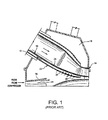
- a typical gas turbine includes a transition piece 10 by which the hot combustion gases from an upstream combustor as represented by the combustion liner 12 are passed to the first stage of a turbine represented at 14. Flow from the gas turbine compressor exits an axial diffuser 16 and enters into a compressor discharge case 18. About 50% of the compressor discharge air passes through apertures 20 formed along and about a transition piece impingement sleeve 22 for flow in an annular region or annulus 24 (or, second flow annulus) between the transition piece 10 and the radially outer transition piece impingement sleeve 22.
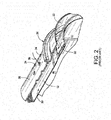
- FIG. 2 illustrates the connection between the transition piece 10 and the combustor flow sleeve 28 as it would appear at the far left hand side of FIG. 1 .
- the impingement sleeve 22 (or second flow sleeve) of the transition piece 10 is received in a telescoping relationship in a mounting flange 26 on the aft end of the combustor flow sleeve 28 (or, first flow sleeve), and the transition piece 10 also receives the combustion liner 12 in a telescoping relationship.
- the combustor flow sleeve 28 surrounds the combustion liner 12 creating a flow annulus 30 (or, first flow annulus) therebetween. It can be seen from the flow arrow 32 in FIG.
- a typical can annular reverse-flow combustor is shown that is driven by the combustion gases from a fuel where a flowing medium with a high energy content, i.e., the combustion gases, produces a rotary motion as a result of being deflected by rings of blading mounted on a rotor.
- discharge air from the compressor (compressed to a pressure on the order of about 250 400 lb/in 2 ) reverses direction as it passes over the outside of the combustion liners (one shown at 12) and again as it enters the combustion liner 12 enroute to the turbine (first stage indicated at 14).
- Compressed air and fuel are burned in the combustion chamber, producing gases with a temperature of between about 1500° F and about 2800° F. These combustion gases flow at a high velocity into turbine section 14 via transition piece 10.
- Hot gases from the combustion section in combustion liner 12 flow therefrom into section 16.
- section 16 There is a transition region indicated generally at 46 in FIG. 2 between these two sections.
- the hot gas temperatures at the aft end of section 12, the inlet portion of region 46 is on the order of about 2800° F.
- the liner metal temperature at the downstream, outlet portion of region 46 is generally on the order of 1400° F to 1550° F.
- liner 12 is provided through which cooling air is flowed. The cooling air serves to draw off heat from the liner and thereby significantly lower the liner metal temperature relative to that of the hot gases.
- FIG. 3 represents one example of the metal temperatures of the combustion liner in a gas turbine.
- the flame nozzles 310 may be pointed in an offset direction, with respect to an axial direction of the combustion liner, to induce a swirl in the combustion gases. Alternatively, the flame nozzles may be directed substantially downstream but the vanes (not shown) in the nozzle induce an exiting swirl.
- the fuel nozzles and resulting combustion products generate temperature zones or hot streaks 320, as bounded by the dotted lines.
- a hot streak in one example, is defined by a region having temperatures of between about 1,000° F to about 1,800° F. These hot streaks are one example, and different configurations or alignments of fuel nozzles will produce different patterns or temperatures of hot streaks.
- the hot streaks 320 contain regions of hotter temperatures than in the regions between hot streaks, and these "in-between" regions are cooler than the hot streak regions 320. Further, each hot streak region 320 will contain sub-areas of varying temperatures. For example, area 322 is hotter than area 324.
- a hot streak 320 can be viewed as an elevated temperature zone caused by a combustion zone aligned with a combustion process associated with a fuel nozzle.
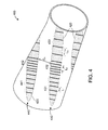
- FIG. 4 illustrates a simplified perspective view of a combustion liner 400 having improved cooling and pressure drop characteristics, according to an aspect of the present invention.
- the combustion liner 400 includes a plurality of turbulators arranged in various groups where each group is aligned with the combustion zone or hot streak pattern of a fuel nozzle.
- Hot streak zones 420 are illustrated by the regions bounded by the dotted lines, but it is to be understood that the present invention can be applied to any combustion liner having any hot streak pattern.
- the hot streaks 420 generally contain hotter temperatures than the surrounding regions not included in the hot streak regions (e.g., the regions between hot streaks 420). Further, each individual hot streak region will contain sub-regions or areas of various temperatures. Accordingly, an improved turbulator configuration is proposed to cool these hot streak regions more effectively while reducing pressure drop over the combustion liner 400.
- a first group of turbulators 430 is aligned with a hot streak or combustion zone of a fuel nozzle, while a second group of turbulators 440 is aligned with another combustion zone (or hot streak) associated with a different fuel nozzle.
- Each individual turbulator may comprise a raised rib or raised portion having any desired shape for the specific application. The regions between the hot streaks do not have the turbulators 430, 440, and this feature reduces pressure drop in areas where turbulators are not required, and provides a more uniform circumferential temperature profile that reduces the global/overall liner stress.
- the first group of turbulators 430 may contain turbulators having variable axial spacing.
- a turbulator sub-group 431 contains multiple turbulators having an axial spacing of L 1
- a turbulator sub-group 432 contains multiple turbulators having an axial spacing of L 2
- a turbulator sub-group 433 contains multiple turbulators having an axial spacing of L 3 .
- L3 is greater than L1
- L1 is greater than L2.
- the turbulator sub-group 432 the hottest portion of the hot streak 420 is covered by the turbulator sub-group 432, a medium temperature portion of the hot streak is covered by the turbulator sub-group 431 and the coolest part of the hot streak is covered by turbulator sub-group 433.
- the turbulators may be configured to have the closest axial spacing in hotter regions, while cooler hot streak regions may have turbulators with a greater axial spacing.
- each group and/or sub-group of turbulators may be circumferentially spaced from a neighboring group of turbulators.
- the first sub-group of turbulators 431 may be circumferentially spaced by a distance C1 from the second sub-group of turbulators 441.
- Each sub-group may also have substantially the same or a different circumferential spacing between a neighboring turbulator sub-group.
- Turbulator sub-group 441 may be spaced substantially the same or a different circumferential distance away from the sub-group turbulators 431, and sub-group turbulators 442 may be spaced the same or a different circumferential distance away from the sub-group turbulators 432.
- each individual turbulator in a single subgroup may have variable axial spacing from adjacent individual turbulators in the same sub-group.
- An advantage of this configuration is that the hottest regions of the hot streaks have greater cooling by the use of closely spaced turbulators, while cooler regions require less cooling and can employ turbulators having a greater axial spacing.
- Another advantage is that pressure drop is increased the most only in regions with the greatest cooling needs (e.g., the area covered by turbulators 432), and other areas have reduced pressure drop due to fewer turbulators or the presence of no turbulators (e.g., the regions between hot streaks 420).
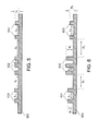
- FIG. 5 illustrates a partial cross-sectional view of the combustion liner 500 having turbulators configured according to an aspect of the present invention.
- a first turbulator sub-group includes individual turbulators 531 having an inter-turbulator spacing of L 1 .
- a second turbulator sub-group includes individual turbulators 532 having an inter-turbulator spacing of L 2 .
- a third turbulator sub-group includes individual turbulators 533 having an inter-turbulator spacing of L 3 .
- L 3 is greater than L 1
- L 1 is greater than L 2 .
- the turbulators 532 may be located in the hottest or highest temperature portion of the hot streak, while the turbulators 533 may be located in a cooler or lower temperature portion of the hot streak.
- the turbulators 531 may be located in a portion of the hot streak having a temperature between the areas covered by turbulators 532 and 533. This configuration limits the maximum pressure drop to only those areas having the highest temperatures, and reduces the pressure drop for other areas of the hot streak and reduces the pressure drop even further for portions of the combustion liner outside the hot streaks.
- FIG. 6 illustrates a partial cross-sectional view of the combustion liner 600 having turbulators configured according to another aspect of the present invention.
- a first turbulator sub-group includes individual turbulators 631 having an inter-turbulator spacing of L 1 and a height of H 1 .
- a second turbulator sub-group includes individual turbulators 632 having an inter-turbulator spacing of L 2 and a height of H 2 .
- a third turbulator sub-group includes individual turbulators 633 having an inter-turbulator spacing of L 3 and a height of H 3 .
- L 3 is greater than L 1
- L 1 is greater than L 2
- H 2 is greater than H 1
- H 1 is greater than H 3 .
- the spacing between turbulator sub-groups can vary, for example S2 is greater than S1.
- the increased height H 2 of the turbulators 632 can help to further cool the hotter portions of the combustion liner in the hotter portions of the hot streak, by increasing turbulence to thereby increase heat transfer.
- a medium height H 1 may be used, while in cooler regions of the hot streak a lower height H 3 may be used for inducing turbulence.
- a group of turbulators is substantially aligned with a hot streak associated with the combustion products of a fuel nozzle, and individual sub-groups of turbulators may have various heights and/or axial spacing between neighboring turbulators.
- first,” “second,” and the like, as well as “primary,” “secondary,” and the like, herein do not denote any amount, order, or importance, but rather are used to distinguish one element from another, and the terms “a” and “an” herein do not denote a limitation of quantity, but rather denote the presence of at least one of the referenced item.
- the term “about”, when used in conjunction with a number in a numerical range, is defined being as within one standard deviation of the number "about” modifies.
- the suffix "(s)” as used herein is intended to include both the singular and the plural of the term that it modifies, thereby including one or more of that term (e.g., the turbulator includes one or more turbulators).
Landscapes
- Engineering & Computer Science (AREA)
- Chemical & Material Sciences (AREA)
- Combustion & Propulsion (AREA)
- Mechanical Engineering (AREA)
- General Engineering & Computer Science (AREA)
- Turbine Rotor Nozzle Sealing (AREA)
Applications Claiming Priority (1)
| Application Number | Priority Date | Filing Date | Title |
|---|---|---|---|
| US13/153,778 US20120304654A1 (en) | 2011-06-06 | 2011-06-06 | Combustion liner having turbulators |
Publications (1)
| Publication Number | Publication Date |
|---|---|
| EP2532962A2 true EP2532962A2 (de) | 2012-12-12 |
Family
ID=46172716
Family Applications (1)
| Application Number | Title | Priority Date | Filing Date |
|---|---|---|---|
| EP12169987A Withdrawn EP2532962A2 (de) | 2011-06-06 | 2012-05-30 | Brennermantel mit Turbulatoren |
Country Status (3)
| Country | Link |
|---|---|
| US (1) | US20120304654A1 (de) |
| EP (1) | EP2532962A2 (de) |
| CN (1) | CN102818287A (de) |
Cited By (3)
| Publication number | Priority date | Publication date | Assignee | Title |
|---|---|---|---|---|
| EP3205829A1 (de) * | 2016-02-12 | 2017-08-16 | General Electric Company | Konturierung eines strömungskanals |
| EP3667167A1 (de) * | 2018-12-10 | 2020-06-17 | United Technologies Corporation | Bevorzugte flussverteilung für gasturbinentriebwerkskomponente |
| EP4675174A1 (de) * | 2024-07-03 | 2026-01-07 | Doosan Enerbility Co., Ltd. | Brennkammer und gasturbine damit |
Families Citing this family (10)
| Publication number | Priority date | Publication date | Assignee | Title |
|---|---|---|---|---|
| US9511447B2 (en) * | 2013-12-12 | 2016-12-06 | General Electric Company | Process for making a turbulator by additive manufacturing |
| US9297532B2 (en) * | 2011-12-21 | 2016-03-29 | Siemens Aktiengesellschaft | Can annular combustion arrangement with flow tripping device |
| EP2971973B1 (de) * | 2013-03-14 | 2018-02-21 | United Technologies Corporation | Brennkammerplatte und brennkammer mit hitzeschild mit erhöhter beständigkeit |
| US10309652B2 (en) * | 2014-04-14 | 2019-06-04 | Siemens Energy, Inc. | Gas turbine engine combustor basket with inverted platefins |
| US9989255B2 (en) | 2014-07-25 | 2018-06-05 | General Electric Company | Liner assembly and method of turbulator fabrication |
| US10260751B2 (en) * | 2015-09-28 | 2019-04-16 | Pratt & Whitney Canada Corp. | Single skin combustor with heat transfer enhancement |
| US9638477B1 (en) * | 2015-10-13 | 2017-05-02 | Caterpillar, Inc. | Sealless cooling device having manifold and turbulator |
| US10830448B2 (en) * | 2016-10-26 | 2020-11-10 | Raytheon Technologies Corporation | Combustor liner panel with a multiple of heat transfer augmentors for a gas turbine engine combustor |
| US11306918B2 (en) * | 2018-11-02 | 2022-04-19 | Chromalloy Gas Turbine Llc | Turbulator geometry for a combustion liner |
| CN115218220B (zh) * | 2022-09-01 | 2023-01-17 | 中国航发四川燃气涡轮研究院 | 一种主燃烧室热斑迁移控制设计方法 |
Family Cites Families (7)
| Publication number | Priority date | Publication date | Assignee | Title |
|---|---|---|---|---|
| EP1136651A1 (de) * | 2000-03-22 | 2001-09-26 | Siemens Aktiengesellschaft | Kühlsystem für eine Turbinenschaufel |
| US20020066273A1 (en) * | 2000-12-04 | 2002-06-06 | Mitsubishi Heavy Industries, Ltd. | Plate fin and combustor using the plate fin |
| CA2476803C (en) * | 2003-08-14 | 2010-10-26 | Mitsubishi Heavy Industries, Ltd. | Heat exchanging wall, gas turbine using the same, and flying body with gas turbine engine |
| US7137782B2 (en) * | 2004-04-27 | 2006-11-21 | General Electric Company | Turbulator on the underside of a turbine blade tip turn and related method |
| GB0601413D0 (en) * | 2006-01-25 | 2006-03-08 | Rolls Royce Plc | Wall elements for gas turbine engine combustors |
| US7757492B2 (en) * | 2007-05-18 | 2010-07-20 | General Electric Company | Method and apparatus to facilitate cooling turbine engines |
| US8544277B2 (en) * | 2007-09-28 | 2013-10-01 | General Electric Company | Turbulated aft-end liner assembly and cooling method |
-
2011
- 2011-06-06 US US13/153,778 patent/US20120304654A1/en not_active Abandoned
-
2012
- 2012-05-30 EP EP12169987A patent/EP2532962A2/de not_active Withdrawn
- 2012-06-06 CN CN201210184366XA patent/CN102818287A/zh active Pending
Non-Patent Citations (1)
| Title |
|---|
| None |
Cited By (7)
| Publication number | Priority date | Publication date | Assignee | Title |
|---|---|---|---|---|
| EP3205829A1 (de) * | 2016-02-12 | 2017-08-16 | General Electric Company | Konturierung eines strömungskanals |
| US10436068B2 (en) | 2016-02-12 | 2019-10-08 | General Electric Company | Flowpath contouring |
| EP3667167A1 (de) * | 2018-12-10 | 2020-06-17 | United Technologies Corporation | Bevorzugte flussverteilung für gasturbinentriebwerkskomponente |
| US11125434B2 (en) | 2018-12-10 | 2021-09-21 | Raytheon Technologies Corporation | Preferential flow distribution for gas turbine engine component |
| US11493205B2 (en) | 2018-12-10 | 2022-11-08 | Raytheon Technologies Corporation | Preferential flow distribution for gas turbine engine component |
| EP4191137B1 (de) * | 2018-12-10 | 2025-03-05 | RTX Corporation | Brennkammerteil mit bevorzugtem strömungsverlauf |
| EP4675174A1 (de) * | 2024-07-03 | 2026-01-07 | Doosan Enerbility Co., Ltd. | Brennkammer und gasturbine damit |
Also Published As
| Publication number | Publication date |
|---|---|
| CN102818287A (zh) | 2012-12-12 |
| US20120304654A1 (en) | 2012-12-06 |
Similar Documents
| Publication | Publication Date | Title |
|---|---|---|
| EP2532962A2 (de) | Brennermantel mit Turbulatoren | |
| EP2481983B1 (de) | Turbulenz erzeugende Hinterkantenverkleidungsanordnung und Kühlungsverfahren für Gasturbinenbrennkammer | |
| US7010921B2 (en) | Method and apparatus for cooling combustor liner and transition piece of a gas turbine | |
| EP1413829B1 (de) | Brennkammerwand mit umgekehrten Wirbelelementen | |
| US20090120093A1 (en) | Turbulated aft-end liner assembly and cooling method | |
| EP2211105A2 (de) | Hinterkantenverkleidungsanordnung einer Brennkammerwand mit Turbulatoren und dazugehöriges Kühlungsverfahren | |
| US9134028B2 (en) | Combustor for gas turbine engine | |
| US20120181354A1 (en) | Combustor nozzle and method for fabricating the combustor nozzle | |
| EP2375160A2 (de) | Kühlsystem mit abgewinkelter Dichtung | |
| EP2864707A1 (de) | Turbinenmotorbrennkammerwand mit ungleichmässiger verteilung von effusionsöffnungen | |
| EP2713106A1 (de) | System und Verfahren zur Erzeugung einer Drallströmung | |
| US20170356652A1 (en) | Combustor Effusion Plate Assembly | |
| US10890327B2 (en) | Liner of a gas turbine engine combustor including dilution holes with airflow features | |
| EP2230456A2 (de) | Brennermantel mit Mischlochansatz | |
| EP3470628A1 (de) | Hinterrahmenanordnung für gasturbinenübergangsstück | |
| US9890954B2 (en) | Combustor cap assembly | |
| US20190249875A1 (en) | Liner for a Gas Turbine Engine Combustor | |
| US11215072B2 (en) | Aft frame assembly for gas turbine transition piece | |
| CA2939289C (en) | Single skin combustor with heat transfer enhancement | |
| US9964308B2 (en) | Combustor cap assembly | |
| US20100300107A1 (en) | Method and flow sleeve profile reduction to extend combustor liner life | |
| CN109416180B (zh) | 用于涡轮发动机中的燃烧器组件及其装配方法 |
Legal Events
| Date | Code | Title | Description |
|---|---|---|---|
| PUAI | Public reference made under article 153(3) epc to a published international application that has entered the european phase |
Free format text: ORIGINAL CODE: 0009012 |
|
| AK | Designated contracting states |
Kind code of ref document: A2 Designated state(s): AL AT BE BG CH CY CZ DE DK EE ES FI FR GB GR HR HU IE IS IT LI LT LU LV MC MK MT NL NO PL PT RO RS SE SI SK SM TR |
|
| AX | Request for extension of the european patent |
Extension state: BA ME |
|
| STAA | Information on the status of an ep patent application or granted ep patent |
Free format text: STATUS: THE APPLICATION IS DEEMED TO BE WITHDRAWN |
|
| 18D | Application deemed to be withdrawn |
Effective date: 20141202 |