EP2532966A2 - Verbrennungsdüse und Verfahren zur Änderung der Verbrennungsdüse - Google Patents
Verbrennungsdüse und Verfahren zur Änderung der Verbrennungsdüse Download PDFInfo
- Publication number
- EP2532966A2 EP2532966A2 EP12171075A EP12171075A EP2532966A2 EP 2532966 A2 EP2532966 A2 EP 2532966A2 EP 12171075 A EP12171075 A EP 12171075A EP 12171075 A EP12171075 A EP 12171075A EP 2532966 A2 EP2532966 A2 EP 2532966A2
- Authority
- EP
- European Patent Office
- Prior art keywords
- downstream
- passage
- section
- frusto
- nozzle
- Prior art date
- Legal status (The legal status is an assumption and is not a legal conclusion. Google has not performed a legal analysis and makes no representation as to the accuracy of the status listed.)
- Granted
Links
- 238000000034 method Methods 0.000 title claims abstract description 17
- 238000002485 combustion reaction Methods 0.000 title description 7
- 239000012530 fluid Substances 0.000 claims abstract description 24
- 238000003754 machining Methods 0.000 claims abstract description 11
- 238000004891 communication Methods 0.000 claims abstract description 10
- 238000011144 upstream manufacturing Methods 0.000 claims description 20
- 238000005336 cracking Methods 0.000 description 13
- 239000000446 fuel Substances 0.000 description 6
- 229910001092 metal group alloy Inorganic materials 0.000 description 6
- 238000001816 cooling Methods 0.000 description 4
- 230000007704 transition Effects 0.000 description 4
- 239000000567 combustion gas Substances 0.000 description 3
- 230000000295 complement effect Effects 0.000 description 3
- 239000007789 gas Substances 0.000 description 3
- 239000000463 material Substances 0.000 description 2
- 238000003801 milling Methods 0.000 description 2
- 238000012986 modification Methods 0.000 description 2
- 230000004048 modification Effects 0.000 description 2
- 230000008569 process Effects 0.000 description 2
- 230000001154 acute effect Effects 0.000 description 1
- 239000002537 cosmetic Substances 0.000 description 1
- 239000003085 diluting agent Substances 0.000 description 1
- 239000007800 oxidant agent Substances 0.000 description 1
- 230000001590 oxidative effect Effects 0.000 description 1
- 230000037361 pathway Effects 0.000 description 1
- 239000012255 powdered metal Substances 0.000 description 1
- 230000002028 premature Effects 0.000 description 1
- 239000012720 thermal barrier coating Substances 0.000 description 1
Images


Classifications
-
- F—MECHANICAL ENGINEERING; LIGHTING; HEATING; WEAPONS; BLASTING
- F23—COMBUSTION APPARATUS; COMBUSTION PROCESSES
- F23R—GENERATING COMBUSTION PRODUCTS OF HIGH PRESSURE OR HIGH VELOCITY, e.g. GAS-TURBINE COMBUSTION CHAMBERS
- F23R3/00—Continuous combustion chambers using liquid or gaseous fuel
- F23R3/28—Continuous combustion chambers using liquid or gaseous fuel characterised by the fuel supply
- F23R3/283—Attaching or cooling of fuel injecting means including supports for fuel injectors, stems, or lances
-
- F—MECHANICAL ENGINEERING; LIGHTING; HEATING; WEAPONS; BLASTING
- F23—COMBUSTION APPARATUS; COMBUSTION PROCESSES
- F23R—GENERATING COMBUSTION PRODUCTS OF HIGH PRESSURE OR HIGH VELOCITY, e.g. GAS-TURBINE COMBUSTION CHAMBERS
- F23R2900/00—Special features of, or arrangements for continuous combustion chambers; Combustion processes therefor
- F23R2900/00005—Preventing fatigue failures or reducing mechanical stress in gas turbine components
-
- F—MECHANICAL ENGINEERING; LIGHTING; HEATING; WEAPONS; BLASTING
- F23—COMBUSTION APPARATUS; COMBUSTION PROCESSES
- F23R—GENERATING COMBUSTION PRODUCTS OF HIGH PRESSURE OR HIGH VELOCITY, e.g. GAS-TURBINE COMBUSTION CHAMBERS
- F23R3/00—Continuous combustion chambers using liquid or gaseous fuel
- F23R3/28—Continuous combustion chambers using liquid or gaseous fuel characterised by the fuel supply
Definitions
- the present invention generally involves a combustor nozzle and a method for modifying the combustor nozzle.
- various embodiments of the present invention provide a combustor nozzle having one or more passages with a frusto-conical or frusto-spherical surface that enhances cracking fatigue resistance of the combustor nozzle.
- Combustors are commonly used to ignite fuel to produce combustion gases having a high temperature and pressure.
- Combustor nozzles typically include a body or a downstream surface at a nozzle tip, and a working fluid and/or fuel is supplied through the nozzle tip to a combustion chamber where the combustion occurs.
- the temperature difference between the working fluid and fuel on one side of the nozzle tip and the combustion gases on the other side of the nozzle tip creates a substantial thermal gradient across the nozzle tip that may produce cracking or premature failure in the nozzle tip.
- the nozzle tip is often forged from metal alloys and may also be coated with a thermal barrier coating to enhance fatigue resistance to cracking.
- cooling holes or passages may be formed through the nozzle tip to allow a portion of the working fluid and/or fuel to pass through the nozzle tip to cool the downstream surface and reduce the temperature difference across the nozzle tip.
- the holes or passages may be machined into the nozzle tip using various methods known in the art. For example, electron discharge machining (EDM) may be used to melt the forged metal alloy to create the holes or passages.
- EDM electron discharge machining
- the high temperatures associated with the EDM process leaves a recast layer inside the holes or passages, and the recast layer is typically substantially less resistant to fatigue cracking than the original forged metal alloy.
- holes and passages that are angled with respect to an axial centerline of the nozzle tip to enhance cooling to the nozzle tip may result in unsupported portions of the nozzle tip that are more susceptible to fatigue cracking.
- One embodiment of the present invention is a combustor nozzle that includes a downstream surface having an axial centerline.
- a plurality of passages extending through the downstream surface provide fluid communication through the downstream surface.
- a downstream section of each passage has at least one of a frusto-conical or frusto-spherical shape.
- a combustor nozzle that includes a body having an upstream side and a downstream side.
- a plurality of passages extending through the body provide fluid communication from the upstream side to the downstream side.
- At least one of a frusto-conical or frusto-spherical surface in each passage is proximate to the downstream side of the body.
- the present invention may also include a method for modifying a combustor nozzle that includes machining a downstream side of a body to remove a recast surface in a plurality of passages that provide fluid communication through the body.
- the method may further include machining a downstream section in each passage to form at least one of a frusto-conical or frusto-spherical surface in each passage proximate to the downstream side of the body.
- the combustor nozzle may include a plurality of passages through a body or a downstream surface, and each passage may include a frusto-conical or frusto-spherical surface or downstream section.
- the frusto-conical or frusto-spherical surface or downstream section may reduce or avoid unsupported portions of the body or downstream surface.
- the frusto-conical or frusto-spherical surface or downstream section may replace a previously existing recast surface in each passage that further enhances the fatigue resistance to cracking.
- Fig. 1 shows a simplified cross-section view of an exemplary combustor 10, such as would be included in a gas turbine.
- a casing 12 may surround the combustor 10 to contain the compressed working fluid flowing to the combustor 10.
- the combustor 10 may include one or more nozzles 14 radially arranged between a cap 16 and an end cover 18.
- Various embodiments of the combustor 10 may include different numbers and arrangements of nozzles 14.
- the cap 16 and a liner 20 generally surround and define a combustion chamber 22 located downstream from the nozzles 14, and a transition piece 24 downstream from the liner 20 connects the combustion chamber 22 to a turbine inlet 26.
- upstream and downstream refer to the relative location of components in a fluid pathway.
- component A is upstream from component B if a fluid flows from component A to component B.
- component B is downstream from component A if component B receives a fluid flow from component A.
- An impingement sleeve 28 with flow holes 30 may surround the transition piece 24 to define an annular passage 32 between the impingement sleeve 28 and the transition piece 24.
- the compressed working fluid may pass through the flow holes 30 in the impingement sleeve 28 to flow through the annular passage 32 to provide convective cooling to the transition piece 24 and liner 20.
- the compressed working fluid reaches the end cover 18, the compressed working fluid reverses direction to flow through the one or more nozzles 14 where it mixes with fuel before igniting in the combustion chamber 22 to produce combustion gases having a high temperature and pressure.
- Figure 2 provides a cross-sectional perspective view of an exemplary nozzle 14 shown in Fig. 1 .
- the nozzle 14 may comprise a shroud 34 that circumferentially surrounds at least a portion of a center body 36 to define an annular passage 38 between the shroud 34 and the center body 36.
- At least a portion of the working fluid may enter the nozzle 14 through the annular passage 38, and one or more swirler vanes 40 between the shroud 34 and the center body 36 may impart a tangential velocity to the compressed working fluid flowing through the nozzle 14.
- the center body 36 may extend axially from the end cover 18 to a nozzle tip 42, and the nozzle tip 42 may be axially aligned with or parallel to an axial centerline 44 of the nozzle 14. In this manner, the center body 36 provides fluid communication from the end cover 18, through the center body 36, and out of the nozzle tip 42.
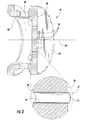
- Fig. 3 provides an enlarged perspective cross-section view of an exemplary nozzle tip 42 shown in Fig. 2 .
- the nozzle tip 42 generally comprises a body 46 having an upstream side 48, a downstream side 50, and a downstream surface 52.
- the body 46 and/or downstream surface 52 may be cast, forged, or sintered from a metal alloy or powdered metal allow to enhance the fatigue resistance of the nozzle tip 42 proximate to the combustion chamber 22.
- the nozzle tip 42 may further include a plurality of holes or passages 54 extending through the body 46 and/or downstream surface 52. As shown in the particular embodiment illustrated in Fig.
- the holes or passages 54 may be aligned substantially parallel to the axial centerline 44 and provide fluid communication from the upstream side 48 to the downstream side 50 or through the body 46 and/or downstream surface 52.
- the passages 54 allow a fluid, such as a fuel, an oxidant, or a diluent, to flow through the body 46 and/or downstream surface 52 to cool the body 46, the downstream side 50 of the body 46, and/or downstream surface 52.
- the holes or passages 54 may be machined into the nozzle tip 42 using various methods known in the art. For example, electron discharge machining (EDM) may be used to melt the forged metal alloy to create the holes or passages 54. However, as shown in Fig. 3 , the high temperatures associated with the EDM process leaves a recast layer or surface 56 inside the holes or passages 54, and the recast surface 56 is typically substantially less resistant to fatigue cracking than the original forged metal alloy.
- EDM electron discharge machining
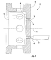
- Figs. 4 and 5 provide side plan views of the exemplary nozzle tip 42 shown in Fig. 3 being modified according to a first embodiment of the present invention.
- a machine such as a drill or mill may be positioned above the body 46 and precisely aligned with one or more of the passages 54.
- a drill bit 58 or other milling surface may then be inserted into the passage 54 to remove at least a portion of the downstream surface 52 and interior wall of the passage 54.
- the drill bit 58 may comprise, for example, a frusto-conical shape 60 to produce a corresponding or complementary frusto-conical shape or surface 62 inside each passage 54 proximate to the downstream side 50 of the body 46.
- the resulting passage 54 comprises an upstream section 64 and a downstream section 66, with the fatigue susceptible recast surface 56 removed from the downstream section 66 but still remaining in the upstream section 64.
- each resulting passage 54 including the downstream section 66, is generally symmetrical.
- each downstream section 66 forms an angle 68 with the downstream side or surface 50, 52, and the angle 68 between the downstream section 66 and the downstream side or surface 50, 52 is greater than or equal to approximately 90 degrees.
- each downstream section 66 forms an angle 70 with the upstream section 64, and the angle 70 between the downstream section 66 and the upstream section 64 is greater than or equal to approximately 90 degrees.
- the angles 68, 70 between the downstream section 66 and the downstream side or surface 50, 52 and/or the upstream section 64 reduce fatigue cracking by providing additional support to the downstream side or surface 50, 52 and/or upstream section 64, respectively.
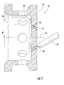
- Fig. 6 provides an enlarged perspective cross-section view of another exemplary nozzle tip 42 shown in Fig. 2 .
- the nozzle tip 42 again generally comprises a body 46, an upstream side 48, a downstream side 50, a downstream surface 52, a plurality passages 54, and a recast surface 56 as previously described with respect to the nozzle tip 42 shown in Figs. 3-5 .
- the passages 54 are angled radially and/or circumferentially with respect to the axial centerline 44 to enhance cooling to the downstream side or surface 50, 52 by swirling the fluid flowing through the passages 54.
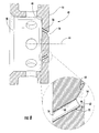
- Figs. 7 and 8 provide side plan views of the exemplary nozzle tip 42 shown in Fig. 6 being modified according to a second embodiment of the present invention.
- a machine such as a drill or mill may again be positioned above the body 46, and the drill bit 58 or other milling surface may be inserted into the passage 54 to remove at least a portion of the downstream surface 52 and interior wall of the passage 54.
- the frusto-conical shape 60 of the drill bit 58 again produces the corresponding or complementary frusto-conical shape or surface 62 inside each passage 54 proximate to the downstream side 50 of the body 46.
- the fatigue susceptible recast surface 56 has again been removed from the downstream section 66 but still remains in the upstream section 64.
- each resulting passage 54 including the downstream section 66, is generally asymmetrical.
- the angle 68 between the downstream section 66 and the downstream side or surface 50, 52 is approximately 90 degrees around a portion of the downstream section 66 and an obtuse angle around the remainder of the downstream section 66.
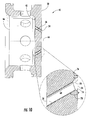
- Figs. 9 and 10 provide side plan views of the exemplary nozzle tip 42 shown in Fig. 6 being modified according to a third embodiment of the present invention.
- the drill bit 58 may comprise a ball-nosed or frusto-spherical shape 72 to produce a corresponding or complementary frusto-spherical shape or surface 74 inside each passage 54 proximate to the downstream side 50 of the body 46.
- the frusto-spherical shape 72 of the drill bit 58 allows the drill bit 58 to be inserted into the passage 54 substantially parallel to the axial centerline 44 or perpendicular to the downstream side 50 without removing excessive amounts of material on one side of the passage 54 and while still avoiding forming an acute angle between the frusto-spherical surface 74 and the downstream side 50.
- the frusto-spherical shape or surface 74 forms an angle 76 with the downstream side or surface 50, 52 that is approximately 90 degrees around a portion of the downstream section 66 and an obtuse angle around the remainder of the downstream section 66.
- the frusto-spherical shape or surface 74 forms an angle 78 with the upstream section 64 that is greater than or equal to approximately 90 degrees.
Landscapes
- Engineering & Computer Science (AREA)
- Chemical & Material Sciences (AREA)
- Combustion & Propulsion (AREA)
- Mechanical Engineering (AREA)
- General Engineering & Computer Science (AREA)
- Turbine Rotor Nozzle Sealing (AREA)
- Nozzles (AREA)
- Gas Burners (AREA)
- Perforating, Stamping-Out Or Severing By Means Other Than Cutting (AREA)
Applications Claiming Priority (1)
| Application Number | Priority Date | Filing Date | Title |
|---|---|---|---|
| US13/153,499 US9052113B1 (en) | 2011-06-06 | 2011-06-06 | Combustor nozzle and method for modifying the combustor nozzle |
Publications (3)
| Publication Number | Publication Date |
|---|---|
| EP2532966A2 true EP2532966A2 (de) | 2012-12-12 |
| EP2532966A3 EP2532966A3 (de) | 2015-04-22 |
| EP2532966B1 EP2532966B1 (de) | 2016-09-14 |
Family
ID=46197165
Family Applications (1)
| Application Number | Title | Priority Date | Filing Date |
|---|---|---|---|
| EP12171075.0A Not-in-force EP2532966B1 (de) | 2011-06-06 | 2012-06-06 | Verbrennungsdüse und Verfahren zur Änderung der Verbrennungsdüse |
Country Status (3)
| Country | Link |
|---|---|
| US (1) | US9052113B1 (de) |
| EP (1) | EP2532966B1 (de) |
| CN (1) | CN102818283B (de) |
Family Cites Families (15)
| Publication number | Priority date | Publication date | Assignee | Title |
|---|---|---|---|---|
| US5303554A (en) | 1992-11-27 | 1994-04-19 | Solar Turbines Incorporated | Low NOx injector with central air swirling and angled fuel inlets |
| CN1056916C (zh) | 1993-09-28 | 2000-09-27 | 德士古发展公司 | 部分氧化方法及其中所采用的燃烧器 |
| US6758045B2 (en) | 2002-08-30 | 2004-07-06 | General Electric Company | Methods and apparatus for operating gas turbine engines |
| US6823677B2 (en) | 2002-09-03 | 2004-11-30 | Pratt & Whitney Canada Corp. | Stress relief feature for aerated gas turbine fuel injector |
| US6851263B2 (en) | 2002-10-29 | 2005-02-08 | General Electric Company | Liner for a gas turbine engine combustor having trapped vortex cavity |
| US7028622B2 (en) | 2003-04-04 | 2006-04-18 | Maxon Corporation | Apparatus for burning pulverized solid fuels with oxygen |
| US7744021B2 (en) * | 2006-03-09 | 2010-06-29 | Belanger, Inc. | Carwash spray nozzle and washing system using same |
| US20080271457A1 (en) | 2007-05-01 | 2008-11-06 | General Electric Company | Cooling Holes For Gas Turbine Combustor Having A Non-Uniform Diameter Therethrough |
| US7966820B2 (en) | 2007-08-15 | 2011-06-28 | General Electric Company | Method and apparatus for combusting fuel within a gas turbine engine |
| US20090169394A1 (en) * | 2007-12-28 | 2009-07-02 | General Electric Company | Method of forming cooling holes and turbine airfoil with hybrid-formed cooling holes |
| US20090200403A1 (en) * | 2008-02-08 | 2009-08-13 | David Ling-Shun Hung | Fuel injector |
| US8261554B2 (en) * | 2008-09-17 | 2012-09-11 | General Electric Company | Fuel nozzle tip assembly |
| US8495881B2 (en) | 2009-06-02 | 2013-07-30 | General Electric Company | System and method for thermal control in a cap of a gas turbine combustor |
| US8484978B2 (en) | 2009-11-12 | 2013-07-16 | General Electric Company | Fuel nozzle assembly that exhibits a frequency different from a natural operating frequency of a gas turbine engine and method of assembling the same |
| CN104136851A (zh) | 2012-02-21 | 2014-11-05 | 通用电气公司 | 燃烧器喷嘴以及向燃烧器供应燃料的方法 |
-
2011
- 2011-06-06 US US13/153,499 patent/US9052113B1/en not_active Expired - Fee Related
-
2012
- 2012-06-06 EP EP12171075.0A patent/EP2532966B1/de not_active Not-in-force
- 2012-06-06 CN CN201210185741.2A patent/CN102818283B/zh not_active Expired - Fee Related
Non-Patent Citations (1)
| Title |
|---|
| None |
Also Published As
| Publication number | Publication date |
|---|---|
| CN102818283B (zh) | 2016-02-17 |
| CN102818283A (zh) | 2012-12-12 |
| EP2532966B1 (de) | 2016-09-14 |
| US9052113B1 (en) | 2015-06-09 |
| EP2532966A3 (de) | 2015-04-22 |
Similar Documents
| Publication | Publication Date | Title |
|---|---|---|
| US8756934B2 (en) | Combustor cap assembly | |
| US9316396B2 (en) | Hot gas path duct for a combustor of a gas turbine | |
| EP3282191B1 (de) | Pilotvormischungsdüse und brennstoffdüsenanordnung | |
| US9297533B2 (en) | Combustor and a method for cooling the combustor | |
| US9556795B2 (en) | Integrated heat shield | |
| EP3315866B1 (de) | Brennkammeranordnung mit montierter hilfskomponente | |
| EP3156597B1 (de) | Kühllöcher einer turbine | |
| US8579211B2 (en) | System and method for enhancing flow in a nozzle | |
| US9784116B2 (en) | Turbine shroud assembly | |
| EP2949904B1 (de) | Verbrenner und gasturbine | |
| US8555649B2 (en) | Fuel nozzle swirler assembly | |
| US8646279B2 (en) | Segment component in high-temperature casting material for an annular combustion chamber, annular combustion chamber for an aircraft engine, aircraft engine and method for the manufacture of an annular combustion chamber | |
| US11499434B2 (en) | Cooled airfoil and method of making | |
| EP2657606A2 (de) | Brennkammer und Verfahren zur Reparatur der Brennkammer | |
| KR102715377B1 (ko) | 에어포일에 대한 2개의 부분 냉각 통로 | |
| JP6161945B2 (ja) | 燃料ノズル | |
| JP2019105437A5 (de) | ||
| US8794544B2 (en) | Combustor nozzle and method for modifying the combustor nozzle | |
| CN109667668A (zh) | 用于燃气涡轮过渡件的后框架组件 | |
| US9052113B1 (en) | Combustor nozzle and method for modifying the combustor nozzle | |
| EP3270062B1 (de) | Vordiffusor mit hoher schräglage | |
| EP3748133B1 (de) | Ermüdungsbeständige schaufelaussenluftdichtung | |
| EP2484475B1 (de) | Verfahren zum Herstellen eines turbinenbauteils unter verwendung eines Keils ; vollringformiger Turbinenbauteil mit solchem gelötetem Keil | |
| US10830072B2 (en) | Turbomachine airfoil | |
| US20120305677A1 (en) | System for conditioning flow through a nozzle |
Legal Events
| Date | Code | Title | Description |
|---|---|---|---|
| PUAI | Public reference made under article 153(3) epc to a published international application that has entered the european phase |
Free format text: ORIGINAL CODE: 0009012 |
|
| AK | Designated contracting states |
Kind code of ref document: A2 Designated state(s): AL AT BE BG CH CY CZ DE DK EE ES FI FR GB GR HR HU IE IS IT LI LT LU LV MC MK MT NL NO PL PT RO RS SE SI SK SM TR |
|
| AX | Request for extension of the european patent |
Extension state: BA ME |
|
| PUAL | Search report despatched |
Free format text: ORIGINAL CODE: 0009013 |
|
| AK | Designated contracting states |
Kind code of ref document: A3 Designated state(s): AL AT BE BG CH CY CZ DE DK EE ES FI FR GB GR HR HU IE IS IT LI LT LU LV MC MK MT NL NO PL PT RO RS SE SI SK SM TR |
|
| AX | Request for extension of the european patent |
Extension state: BA ME |
|
| RIC1 | Information provided on ipc code assigned before grant |
Ipc: F23R 3/28 20060101AFI20150318BHEP |
|
| 17P | Request for examination filed |
Effective date: 20151022 |
|
| RBV | Designated contracting states (corrected) |
Designated state(s): AL AT BE BG CH CY CZ DE DK EE ES FI FR GB GR HR HU IE IS IT LI LT LU LV MC MK MT NL NO PL PT RO RS SE SI SK SM TR |
|
| GRAP | Despatch of communication of intention to grant a patent |
Free format text: ORIGINAL CODE: EPIDOSNIGR1 |
|
| INTG | Intention to grant announced |
Effective date: 20160511 |
|
| GRAJ | Information related to disapproval of communication of intention to grant by the applicant or resumption of examination proceedings by the epo deleted |
Free format text: ORIGINAL CODE: EPIDOSDIGR1 |
|
| GRAR | Information related to intention to grant a patent recorded |
Free format text: ORIGINAL CODE: EPIDOSNIGR71 |
|
| GRAS | Grant fee paid |
Free format text: ORIGINAL CODE: EPIDOSNIGR3 |
|
| GRAA | (expected) grant |
Free format text: ORIGINAL CODE: 0009210 |
|
| INTC | Intention to grant announced (deleted) | ||
| AK | Designated contracting states |
Kind code of ref document: B1 Designated state(s): AL AT BE BG CH CY CZ DE DK EE ES FI FR GB GR HR HU IE IS IT LI LT LU LV MC MK MT NL NO PL PT RO RS SE SI SK SM TR |
|
| INTG | Intention to grant announced |
Effective date: 20160810 |
|
| REG | Reference to a national code |
Ref country code: GB Ref legal event code: FG4D |
|
| REG | Reference to a national code |
Ref country code: CH Ref legal event code: EP |
|
| REG | Reference to a national code |
Ref country code: IE Ref legal event code: FG4D |
|
| REG | Reference to a national code |
Ref country code: AT Ref legal event code: REF Ref document number: 829432 Country of ref document: AT Kind code of ref document: T Effective date: 20161015 |
|
| REG | Reference to a national code |
Ref country code: DE Ref legal event code: R096 Ref document number: 602012022700 Country of ref document: DE |
|
| REG | Reference to a national code |
Ref country code: LT Ref legal event code: MG4D |
|
| REG | Reference to a national code |
Ref country code: NL Ref legal event code: MP Effective date: 20160914 |
|
| PG25 | Lapsed in a contracting state [announced via postgrant information from national office to epo] |
Ref country code: FI Free format text: LAPSE BECAUSE OF FAILURE TO SUBMIT A TRANSLATION OF THE DESCRIPTION OR TO PAY THE FEE WITHIN THE PRESCRIBED TIME-LIMIT Effective date: 20160914 Ref country code: NO Free format text: LAPSE BECAUSE OF FAILURE TO SUBMIT A TRANSLATION OF THE DESCRIPTION OR TO PAY THE FEE WITHIN THE PRESCRIBED TIME-LIMIT Effective date: 20161214 Ref country code: LT Free format text: LAPSE BECAUSE OF FAILURE TO SUBMIT A TRANSLATION OF THE DESCRIPTION OR TO PAY THE FEE WITHIN THE PRESCRIBED TIME-LIMIT Effective date: 20160914 Ref country code: HR Free format text: LAPSE BECAUSE OF FAILURE TO SUBMIT A TRANSLATION OF THE DESCRIPTION OR TO PAY THE FEE WITHIN THE PRESCRIBED TIME-LIMIT Effective date: 20160914 Ref country code: RS Free format text: LAPSE BECAUSE OF FAILURE TO SUBMIT A TRANSLATION OF THE DESCRIPTION OR TO PAY THE FEE WITHIN THE PRESCRIBED TIME-LIMIT Effective date: 20160914 |
|
| REG | Reference to a national code |
Ref country code: AT Ref legal event code: MK05 Ref document number: 829432 Country of ref document: AT Kind code of ref document: T Effective date: 20160914 |
|
| PG25 | Lapsed in a contracting state [announced via postgrant information from national office to epo] |
Ref country code: GR Free format text: LAPSE BECAUSE OF FAILURE TO SUBMIT A TRANSLATION OF THE DESCRIPTION OR TO PAY THE FEE WITHIN THE PRESCRIBED TIME-LIMIT Effective date: 20161215 Ref country code: SE Free format text: LAPSE BECAUSE OF FAILURE TO SUBMIT A TRANSLATION OF THE DESCRIPTION OR TO PAY THE FEE WITHIN THE PRESCRIBED TIME-LIMIT Effective date: 20160914 Ref country code: LV Free format text: LAPSE BECAUSE OF FAILURE TO SUBMIT A TRANSLATION OF THE DESCRIPTION OR TO PAY THE FEE WITHIN THE PRESCRIBED TIME-LIMIT Effective date: 20160914 Ref country code: NL Free format text: LAPSE BECAUSE OF FAILURE TO SUBMIT A TRANSLATION OF THE DESCRIPTION OR TO PAY THE FEE WITHIN THE PRESCRIBED TIME-LIMIT Effective date: 20160914 |
|
| PG25 | Lapsed in a contracting state [announced via postgrant information from national office to epo] |
Ref country code: EE Free format text: LAPSE BECAUSE OF FAILURE TO SUBMIT A TRANSLATION OF THE DESCRIPTION OR TO PAY THE FEE WITHIN THE PRESCRIBED TIME-LIMIT Effective date: 20160914 Ref country code: RO Free format text: LAPSE BECAUSE OF FAILURE TO SUBMIT A TRANSLATION OF THE DESCRIPTION OR TO PAY THE FEE WITHIN THE PRESCRIBED TIME-LIMIT Effective date: 20160914 |
|
| PG25 | Lapsed in a contracting state [announced via postgrant information from national office to epo] |
Ref country code: PL Free format text: LAPSE BECAUSE OF FAILURE TO SUBMIT A TRANSLATION OF THE DESCRIPTION OR TO PAY THE FEE WITHIN THE PRESCRIBED TIME-LIMIT Effective date: 20160914 Ref country code: CZ Free format text: LAPSE BECAUSE OF FAILURE TO SUBMIT A TRANSLATION OF THE DESCRIPTION OR TO PAY THE FEE WITHIN THE PRESCRIBED TIME-LIMIT Effective date: 20160914 Ref country code: SM Free format text: LAPSE BECAUSE OF FAILURE TO SUBMIT A TRANSLATION OF THE DESCRIPTION OR TO PAY THE FEE WITHIN THE PRESCRIBED TIME-LIMIT Effective date: 20160914 Ref country code: PT Free format text: LAPSE BECAUSE OF FAILURE TO SUBMIT A TRANSLATION OF THE DESCRIPTION OR TO PAY THE FEE WITHIN THE PRESCRIBED TIME-LIMIT Effective date: 20170116 Ref country code: AT Free format text: LAPSE BECAUSE OF FAILURE TO SUBMIT A TRANSLATION OF THE DESCRIPTION OR TO PAY THE FEE WITHIN THE PRESCRIBED TIME-LIMIT Effective date: 20160914 Ref country code: ES Free format text: LAPSE BECAUSE OF FAILURE TO SUBMIT A TRANSLATION OF THE DESCRIPTION OR TO PAY THE FEE WITHIN THE PRESCRIBED TIME-LIMIT Effective date: 20160914 Ref country code: BE Free format text: LAPSE BECAUSE OF FAILURE TO SUBMIT A TRANSLATION OF THE DESCRIPTION OR TO PAY THE FEE WITHIN THE PRESCRIBED TIME-LIMIT Effective date: 20160914 Ref country code: BG Free format text: LAPSE BECAUSE OF FAILURE TO SUBMIT A TRANSLATION OF THE DESCRIPTION OR TO PAY THE FEE WITHIN THE PRESCRIBED TIME-LIMIT Effective date: 20161214 Ref country code: SK Free format text: LAPSE BECAUSE OF FAILURE TO SUBMIT A TRANSLATION OF THE DESCRIPTION OR TO PAY THE FEE WITHIN THE PRESCRIBED TIME-LIMIT Effective date: 20160914 Ref country code: IS Free format text: LAPSE BECAUSE OF FAILURE TO SUBMIT A TRANSLATION OF THE DESCRIPTION OR TO PAY THE FEE WITHIN THE PRESCRIBED TIME-LIMIT Effective date: 20170114 |
|
| REG | Reference to a national code |
Ref country code: DE Ref legal event code: R097 Ref document number: 602012022700 Country of ref document: DE |
|
| REG | Reference to a national code |
Ref country code: FR Ref legal event code: PLFP Year of fee payment: 6 |
|
| PLBE | No opposition filed within time limit |
Free format text: ORIGINAL CODE: 0009261 |
|
| STAA | Information on the status of an ep patent application or granted ep patent |
Free format text: STATUS: NO OPPOSITION FILED WITHIN TIME LIMIT |
|
| PG25 | Lapsed in a contracting state [announced via postgrant information from national office to epo] |
Ref country code: DK Free format text: LAPSE BECAUSE OF FAILURE TO SUBMIT A TRANSLATION OF THE DESCRIPTION OR TO PAY THE FEE WITHIN THE PRESCRIBED TIME-LIMIT Effective date: 20160914 |
|
| 26N | No opposition filed |
Effective date: 20170615 |
|
| PG25 | Lapsed in a contracting state [announced via postgrant information from national office to epo] |
Ref country code: SI Free format text: LAPSE BECAUSE OF FAILURE TO SUBMIT A TRANSLATION OF THE DESCRIPTION OR TO PAY THE FEE WITHIN THE PRESCRIBED TIME-LIMIT Effective date: 20160914 |
|
| PG25 | Lapsed in a contracting state [announced via postgrant information from national office to epo] |
Ref country code: MC Free format text: LAPSE BECAUSE OF FAILURE TO SUBMIT A TRANSLATION OF THE DESCRIPTION OR TO PAY THE FEE WITHIN THE PRESCRIBED TIME-LIMIT Effective date: 20160914 |
|
| REG | Reference to a national code |
Ref country code: IE Ref legal event code: MM4A |
|
| PG25 | Lapsed in a contracting state [announced via postgrant information from national office to epo] |
Ref country code: IE Free format text: LAPSE BECAUSE OF NON-PAYMENT OF DUE FEES Effective date: 20170606 Ref country code: LU Free format text: LAPSE BECAUSE OF NON-PAYMENT OF DUE FEES Effective date: 20170606 |
|
| REG | Reference to a national code |
Ref country code: FR Ref legal event code: PLFP Year of fee payment: 7 |
|
| PGFP | Annual fee paid to national office [announced via postgrant information from national office to epo] |
Ref country code: FR Payment date: 20180626 Year of fee payment: 7 |
|
| PG25 | Lapsed in a contracting state [announced via postgrant information from national office to epo] |
Ref country code: MT Free format text: LAPSE BECAUSE OF NON-PAYMENT OF DUE FEES Effective date: 20170606 |
|
| PG25 | Lapsed in a contracting state [announced via postgrant information from national office to epo] |
Ref country code: AL Free format text: LAPSE BECAUSE OF FAILURE TO SUBMIT A TRANSLATION OF THE DESCRIPTION OR TO PAY THE FEE WITHIN THE PRESCRIBED TIME-LIMIT Effective date: 20160914 |
|
| PGFP | Annual fee paid to national office [announced via postgrant information from national office to epo] |
Ref country code: DE Payment date: 20180627 Year of fee payment: 7 Ref country code: GB Payment date: 20180627 Year of fee payment: 7 Ref country code: IT Payment date: 20180621 Year of fee payment: 7 |
|
| PGFP | Annual fee paid to national office [announced via postgrant information from national office to epo] |
Ref country code: CH Payment date: 20180704 Year of fee payment: 7 |
|
| PG25 | Lapsed in a contracting state [announced via postgrant information from national office to epo] |
Ref country code: HU Free format text: LAPSE BECAUSE OF FAILURE TO SUBMIT A TRANSLATION OF THE DESCRIPTION OR TO PAY THE FEE WITHIN THE PRESCRIBED TIME-LIMIT; INVALID AB INITIO Effective date: 20120606 |
|
| PG25 | Lapsed in a contracting state [announced via postgrant information from national office to epo] |
Ref country code: CY Free format text: LAPSE BECAUSE OF NON-PAYMENT OF DUE FEES Effective date: 20160914 |
|
| PG25 | Lapsed in a contracting state [announced via postgrant information from national office to epo] |
Ref country code: MK Free format text: LAPSE BECAUSE OF FAILURE TO SUBMIT A TRANSLATION OF THE DESCRIPTION OR TO PAY THE FEE WITHIN THE PRESCRIBED TIME-LIMIT Effective date: 20160914 |
|
| REG | Reference to a national code |
Ref country code: DE Ref legal event code: R119 Ref document number: 602012022700 Country of ref document: DE |
|
| REG | Reference to a national code |
Ref country code: CH Ref legal event code: PL |
|
| GBPC | Gb: european patent ceased through non-payment of renewal fee |
Effective date: 20190606 |
|
| PG25 | Lapsed in a contracting state [announced via postgrant information from national office to epo] |
Ref country code: TR Free format text: LAPSE BECAUSE OF FAILURE TO SUBMIT A TRANSLATION OF THE DESCRIPTION OR TO PAY THE FEE WITHIN THE PRESCRIBED TIME-LIMIT Effective date: 20160914 |
|
| PG25 | Lapsed in a contracting state [announced via postgrant information from national office to epo] |
Ref country code: GB Free format text: LAPSE BECAUSE OF NON-PAYMENT OF DUE FEES Effective date: 20190606 Ref country code: IT Free format text: LAPSE BECAUSE OF NON-PAYMENT OF DUE FEES Effective date: 20190606 Ref country code: DE Free format text: LAPSE BECAUSE OF NON-PAYMENT OF DUE FEES Effective date: 20200101 |
|
| PG25 | Lapsed in a contracting state [announced via postgrant information from national office to epo] |
Ref country code: CH Free format text: LAPSE BECAUSE OF NON-PAYMENT OF DUE FEES Effective date: 20190630 Ref country code: LI Free format text: LAPSE BECAUSE OF NON-PAYMENT OF DUE FEES Effective date: 20190630 |
|
| PG25 | Lapsed in a contracting state [announced via postgrant information from national office to epo] |
Ref country code: FR Free format text: LAPSE BECAUSE OF NON-PAYMENT OF DUE FEES Effective date: 20190630 |