EP2532986A1 - Dispositif de nettoyage - Google Patents
Dispositif de nettoyage Download PDFInfo
- Publication number
- EP2532986A1 EP2532986A1 EP12169538A EP12169538A EP2532986A1 EP 2532986 A1 EP2532986 A1 EP 2532986A1 EP 12169538 A EP12169538 A EP 12169538A EP 12169538 A EP12169538 A EP 12169538A EP 2532986 A1 EP2532986 A1 EP 2532986A1
- Authority
- EP
- European Patent Office
- Prior art keywords
- fluid
- brush
- base part
- coupled
- drive
- Prior art date
- Legal status (The legal status is an assumption and is not a legal conclusion. Google has not performed a legal analysis and makes no representation as to the accuracy of the status listed.)
- Granted
Links
Images

Classifications
-
- F—MECHANICAL ENGINEERING; LIGHTING; HEATING; WEAPONS; BLASTING
- F24—HEATING; RANGES; VENTILATING
- F24S—SOLAR HEAT COLLECTORS; SOLAR HEAT SYSTEMS
- F24S40/00—Safety or protection arrangements of solar heat collectors; Preventing malfunction of solar heat collectors
- F24S40/20—Cleaning; Removing snow
-
- A—HUMAN NECESSITIES
- A46—BRUSHWARE
- A46B—BRUSHES
- A46B13/00—Brushes with driven brush bodies or carriers
- A46B13/001—Cylindrical or annular brush bodies
-
- A—HUMAN NECESSITIES
- A46—BRUSHWARE
- A46B—BRUSHES
- A46B13/00—Brushes with driven brush bodies or carriers
- A46B13/02—Brushes with driven brush bodies or carriers power-driven carriers
- A46B13/04—Brushes with driven brush bodies or carriers power-driven carriers with reservoir or other means for supplying substances
- A46B13/06—Brushes with driven brush bodies or carriers power-driven carriers with reservoir or other means for supplying substances with brush driven by the supplied medium
-
- B—PERFORMING OPERATIONS; TRANSPORTING
- B08—CLEANING
- B08B—CLEANING IN GENERAL; PREVENTION OF FOULING IN GENERAL
- B08B1/00—Cleaning by methods involving the use of tools
- B08B1/30—Cleaning by methods involving the use of tools by movement of cleaning members over a surface
- B08B1/32—Cleaning by methods involving the use of tools by movement of cleaning members over a surface using rotary cleaning members
- B08B1/34—Cleaning by methods involving the use of tools by movement of cleaning members over a surface using rotary cleaning members rotating about an axis parallel to the surface
-
- Y—GENERAL TAGGING OF NEW TECHNOLOGICAL DEVELOPMENTS; GENERAL TAGGING OF CROSS-SECTIONAL TECHNOLOGIES SPANNING OVER SEVERAL SECTIONS OF THE IPC; TECHNICAL SUBJECTS COVERED BY FORMER USPC CROSS-REFERENCE ART COLLECTIONS [XRACs] AND DIGESTS
- Y02—TECHNOLOGIES OR APPLICATIONS FOR MITIGATION OR ADAPTATION AGAINST CLIMATE CHANGE
- Y02E—REDUCTION OF GREENHOUSE GAS [GHG] EMISSIONS, RELATED TO ENERGY GENERATION, TRANSMISSION OR DISTRIBUTION
- Y02E10/00—Energy generation through renewable energy sources
- Y02E10/40—Solar thermal energy, e.g. solar towers
Definitions
- the invention relates to a device for cleaning surfaces with a cleaning head, which comprises at least one base part and at least one brush arrangement attached to the base part, in particular a cylindrical brush roller.
- Such devices are basically known and are used for example for cleaning solar systems.
- the cleaning of solar systems is becoming increasingly important, which is why there is an increasing need for both efficient and cost-effective ways to clean such solar systems.
- the individual modules of solar systems have different widths, so that a cleaning device should offer the opportunity to be able to be used without sacrificing efficiency and handling of solar systems with modules of different widths. Furthermore, it is important that in order to minimize the cleaning costs, working with the cleaning device can take place as quickly and easily as possible. If the cleaning is done with the aid of a fluid, especially water, then it should also be ensured that the water consumption is as low as possible, without, however, impairing the cleaning effect.
- the object of the invention is therefore to develop a cleaning device of the type mentioned in that a cleaning in particular of solar systems in the simplest and most cost-effective manner possible.
- an at least partially integrated in the base part fluid drive for the brush assembly is provided which is adapted to convert the flow energy of the base member under pressure fluid supplied in a cleaning movement of the brush assembly.
- the brush arrangement can be one or more brush rollers rotatably mounted on the base part, which are moved manually or automatically over the surface to be cleaned each time during the cleaning process with continuous self-rotation.
- the integrated fluid drive according to the invention it is also possible to use a fluid, in particular water, which is required in any case to assist cleaning, in addition to generate the cleaning movement of the brush arrangement, in particular the rotation of one or more brush rollers.
- a fluid in particular water
- Heavy and expensive electric motors for driving the brush assembly can be omitted.
- a further simplification is achieved in that it only needs to be provided for the supply of the fluid to the brush arrangement. Additional supply lines are not necessary. This reduces the weight of the cleaning device according to the invention and simplifies their handling.
- a set of a plurality of brush modules which can be axially coupled together to be assembled into a brush assembly, respectively.
- the working width of the brush assembly can be changed and adapted to the respective object to be cleaned.
- the set of brush modules may comprise at least one base module coupled or coupleable to the base part, at least one end module closed axially outside and at least one intermediate module coupled or coupleable between the end module and the base module.
- the coupling between the individual brush modules can be done in particular by screwing. This can be made possible without tools by virtue of the brush modules comprising a receptacle with an internal thread at one axial end and a screw connection with an external thread at the other axial end, or vice versa, so that the brush modules can simply be screwed together.
- the base part in particular centrally, is arranged between two brush arrangements, wherein the axial area occupied by the base part is at least substantially covered by the bristles of at least one of the brush arrangements.
- a symmetrical arrangement which is advantageous in terms of cleaning action and handling can be created insofar as the base part is arranged between two brush modules.
- One advantage of this arrangement is that a single fluid drive can simultaneously drive and in particular set both brush arrangements in rotation. This can save costs and weight.
- such an arrangement with a base part arranged between two brush arrangements initially entails the potential problem that the axial area occupied by the base part is not available for cleaning the respective area.
- the cleaning device can thus leave on the surface a not acted upon by the brush assemblies strip, which must be eliminated by a subsequent cleaning process. In other words, care must be taken to work with a relatively large overlap.
- the brush arrangements need be used to cover the axial area. Rather, it is preferred, although not mandatory, that the bristles jointly cover the axial region both of the brush arrangements arranged on both sides of the base part.
- a particularly advantageous optimization of the cleaning device according to the invention is achieved by an embodiment in which it is provided that the fluid drive is divided on a basic part associated with the driven part and a fluid supply means associated driving part, wherein the two parts of the fluid drive are releasably coupled or coupled together , A ready-functioning completion of the fluid drive is thus given at the intended purpose with the base fluid supply device.
- Such a division makes it possible, in particular, to realize an extremely slim or slim-fitting fluid supply to the fluid drive integrated at least partially in the base part. A potentially leading to banding free axial region between two arranged on both sides of the base member brush assemblies can thereby be minimized from the outset.
- Another advantage of the said division is that at least the driving part of the fluid drive can be easily changed or replaced in order to adapt the working behavior of the cleaning device, in particular the cleaning performance and / or fluid consumption, to the respective application.
- the fluid ejection member can nevertheless constitute the driving part assigned to a fluid supply device in the sense of the above-disclosed division of the fluid drive.
- the fluid ejection member in particular a nozzle, may be a separate, replaceable component.
- the fluid ejecting member may be an integral part of a fluid supply device, however concrete, in particular a lance or a supply line.
- the fluid ejection element extends radially or tangentially relative to a rotation axis of the brush arrangement, at least in the region of the base part.
- the Fluidauscetorgan can be arranged at the end of a fluid supply line, in particular a lance and / or support rod, which is coupled or coupled by mating with the base part.
- the base part may comprise a plug-in receptacle for the fluid supply line or the fluid ejection element, in principle, a reverse configuration is possible, ie, the fluid supply line has a plug-in receptacle, in which a correspondingly formed plug-in part of the base part is to be introduced to assemble the cleaning device ready for operation.
- the fluid ejection element can be exchangeable, in particular for changing the cleaning performance and / or the fluid consumption, wherein in particular a set of fluid ejection elements with different flow cross-sections is provided.
- the fluid ejecting member may be a nozzle or a driving nozzle for acting on a turbine of the fluid drive.
- Possible nozzle sizes i. Diameter of a fluid outlet opening of the nozzle, in particular in the range of 0.5 mm-1.5 mm. It has surprisingly been found that even with a relatively low water consumption of 1, 0 - 1.5 liters per minute, a sufficiently high torque for the rotational drive of two arranged on both sides of the base cylindrical brush rollers can be achieved.
- a pressure of the water provided by a high-pressure cleaner for example, of about 100 bar.
- the cleaning device according to the invention preferably designed such that the water consumption is in the range between 1.0 - 6.0 liters.
- the outer diameter of rotating brush rollers according to the invention for example, in the range of 120 mm - 150 mm.
- a smaller outer diameter allows lower water consumption, with larger brush rollers have the advantage of a larger peripheral speed and thus a higher area performance, ie without affecting the cleaning effect, large rotating rollers can be moved at a higher speed over the respective surface to be cleaned than smaller rollers.
- a comparatively large torque can be applied to a fluid drive achieve.
- the core diameter of the rotating brushes, in particular the outer diameter of a roll shell carrying the brush is in particular about 65 mm.
- the choice of the outer diameter of the brush rollers is also made depending on the inclination angle of the surface to be cleaned.
- the fluid drive can have a drive element driven directly by the fluid, in particular a turbine or a paddle wheel.
- a drive element driven directly by the fluid in particular a turbine or a paddle wheel.
- the fluid drive is operable in different directions of rotation, by rotating a fluid supply line and / or a Fluidaussummeorgans, in particular, this rotation takes place by 180 ° about a longitudinal axis of the fluid supply line or the Fluidaussortorgans.
- Such switching over between the opposite directions of rotation of the fluid drive can take place, for example, in that a fluid supply line carrying a fluid ejection element at the end and / or a region of a fluid supply line and / or a fluid ejection element located upstream of a fluid outlet extends at least substantially radially relative to a rotation axis of the brush arrangement and a fluid outlet is oriented such that, depending on the rotational position of the fluid supply line and / or the Fluidausffleorgans the fluid drive, in particular a turbine or a paddle wheel, is acted upon in different directions of rotation.
- the mentioned radial profile is not mandatory.
- the fluid supply line or the fluid ejection element ie ultimately the direction in which the fluid emerges, can be adjusted so that the fluid drive either in one direction or in the other direction with the exiting fluid is charged.
- a turbine or a paddle wheel for example, is thus applied either "from the front" or "from behind".
- a drive element, in particular a turbine or a paddle wheel, of the fluid drive has blade elements that are designed to be neutral in direction of rotation.
- the fluid drive is equally suitable for a forward drive and a reverse drive.
- the brush assembly may be provided according to a further aspect of the invention with a splash guard.
- the splash guard may include a cover located outside of the bristles of the brush assembly. In principle, this can extend over any angle range which is adapted in accordance with the specific embodiment of the cleaning device, which angle range is e.g. may be up to 180 ° or up to 360 ° with respect to a rotation axis of one or more rotating brush rollers.
- the splash guard may comprise a scraper projecting at least partially into the bristles, relatively to which the brush assembly moves during the cleaning operation and abuts the bristles during the cleaning operation.
- the bristles can be automatically freed in a defined manner at a predetermined location during the cleaning operation of impurities or soiled cleaning fluid. It is avoided in a particularly simple and effective way that an uncontrolled spraying of the contaminants takes place and the cleaning effect is immediately nullified.
- the base part comprises a flat, in particular plate or disc-shaped reinforcement, in particular of metal, which at least partially surrounded by an outer part made of plastic, in particular cast in plastic or molded with plastic is.
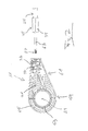
- Fig. 1 shows an embodiment of a double or twin brush of a cleaning device according to the invention comprising two brush assemblies 13, which are arranged on both sides of a base member 11 and connected to the base member 11 such that an integrated into the base member 11 fluid drive (in Fig. 1 not shown) both brush assemblies 13 can move simultaneously with the same direction of rotation in a cleaning movement, in which it is a rotational movement about a common axis of rotation 29 (see. Fig. 2 ).
- Fig. 1 shows in particular a modular construction of the brush assemblies 13, which serves to adapt the working width of the cleaning device to the respective application.
- each brush assembly 13 comprises a base module 17, two intermediate modules 21 and an end module 19.
- the modules can be screwed together.
- a screw portion 55 is provided with an external thread, which can be screwed with an internally threaded screw portion 57 of another module, in this way ultimately couple any number of brush modules together and so to a brush assembly 13 with each to assemble the desired working width.
- the comparison in particular of Fig. 3 and Fig. 4 shows that the brush assemblies 13 according to Fig. 4 each have a small number of brush modules than those of Fig. 3 ,
- the fluid drive and the base part 11 are designed in such a way that fluid flowing into the base part 11 flows into the interior of a bristled outer sheath 49 of the brush arrangement 13 via a receiving section 33 which is explained in more detail below, after which it leaves the fluid drive and from there via outlet openings, not shown emerge at the periphery of the outer jacket 49 and to be able to wet the bristles or the object to be cleaned, the end module 19 is closed axially end.
- the base module 17 includes a transition module 22 that is detachably bolted to a portion of the base module 17.
- the transition module 22 can be regarded as another intermediate module corresponding to the intermediate modules 21.
- the transition module 22 may be identical to or identical to the intermediate modules 21 executed.
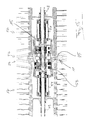
- a special feature of the transition module 22 is that it is bolted to that portion of the base module 17, the axially end a below explained in more detail support assembly with a plug 47, a connector 45 and a support rod 43 holds (see. Fig. 4 ).
- the base member 11 comprises a cylindrical portion 59 whose central axis coincides with the axis of rotation 29 of the brush assemblies 13 and in the manner described in more detail below, an axially extending housing 53 (see. Fig. 4 and 5 ) for a fluid drive.
- the base part 11 comprises a substantially radially projecting feed line section 61, which has a feedthrough 41 which runs tangentially with respect to the rotation axis 29 and also into the feedthrough 41 opening, having an enlarged cross-section receiving portion 33 includes.
- the comparatively narrow feedthrough 41 serves to receive a relatively thin, pin-shaped jet pipe section 63, while the receiving section 33 serves to receive an enlarged enlargement 39 with respect to the diameter relative to the jet pipe section 63, which merges into the jet pipe section 63 in the flow direction of the fluid.
- the jet pipe section 63 and the extension 39 are end portions of a fluid supply line 25, which is in particular designed as a lance and via which the cleaning device according to the invention can be connected to a fluid pressure source, not shown, in particular to a commercial high-pressure cleaner.
- the jet tube 63 and the extension 39 comprehensive end of the line 25 extends in the assembled state with the base part 11 tangential to the axis of rotation 29th
- the base part 11 is provided in the region of the receiving portion 33 with a fuse 37 which engages in the assembled state in a recess 35 of the extension 39 of the line 25 and prevents unintentional pulling out of the line 25 from the base part 11.
- an exchangeable fluid ejection member in the form of a nozzle member 27 is provided at the free end of the jet pipe 63.
- the outlet opening of the nozzle 27 serves as a fluid outlet, which is aligned such that a in Fig. 2 not shown turbine of the fluid drive with a fluid jet is charged.
- the mentioned fluid drive is arranged in that region of the cylindrical portion 59 of the base part 11, which is surrounded by the housing 53 (see. Fig. 4 and 5 ).
- a flat annular disc-shaped flange portion 65 Surrounding the housing 53 in a central region of a flat annular disc-shaped flange portion 65 which is integrally connected to the cylindrical housing 53 and radially projecting from the housing 53, wherein the flange portion 65 of the lead portion 61 extends in the radial direction. Both the flange portion 65 and the lead portion 61 are formed in the direction of the rotation axis 29 extremely narrow or thin to the area occupied by the base member 11 axial region between the two brush assemblies 13 (see. Fig. 1 ) to minimize.
- the base part 11 is formed as a multi-component component, which comprises an inner strength member, in particular in the form of a metal sheet, which is oriented with its flat sides perpendicular to the axis of rotation 29.
- This sheet can be overmolded with plastic to realize the desired shape or structure. Overall, this makes it possible to achieve an extremely stable and, in particular, rigid configuration for the base part 11, this being made possible with a conceivably low weight of the base part 11.
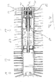
- Fig. 3 shows a brush assembly 13 which is arranged on one side of the base part 11 and thus forms one half of a double or twin brush of a cleaning device according to the invention.
- the brush assembly 13 comprises three identical brush modules 21, 22, wherein the brush module 22 can be referred to as a transition module, as it with the base module 17 is connected by means of a support assembly 67 to the base member 11 and can be offset by means of a fluid drive 15 relative to the base member 11 in rotation.
- the bristles of the two most axially inwardly located bristle discs of the base module with respect to the axis of rotation 29 are arranged inclined, said in the region of the base part 11 located parts 23 of the bristles of the two brush assemblies 13 are directed towards each other.
- FIG. 4 shows the support assembly 17 between the housing 53 of the base member 11 and the outer shell 49 of the base brush module 17 a support rod 43 which is coupled via a connecting piece 45 with a plug 47 which is screwed into the axial end portion of the base brush module 17 and thus carries the outer jacket 49 in the axial end region.
- a further axially inner region of the outer jacket 49 is held by means of an integral holding portion 69 which is supported on the support rod 43.
- the support rod 43 and thus the base brush module 17 and the coupled further brush modules 22, 19 are rotated by means of the fluid drive 15 in rotation, the structure of which will not be discussed in detail here.
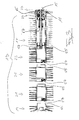
- the fluid drive 15 comprises a central drive member 31 in the form of a turbine or paddle wheel, which by means of the nozzle 27 (see. Fig. 2 ) applied fluid jet and thus is set in rotation.
- a central drive member 31 in the form of a turbine or paddle wheel, which by means of the nozzle 27 (see. Fig. 2 ) applied fluid jet and thus is set in rotation.
- two axially successively connected planetary gear are arranged on each side of this drive member 31, two axially successively connected planetary gear are arranged.
- the planet carrier of the first planetary gear serves as a sun gear for the second planetary gear.
- the two axially outer planet carrier respectively drive the support rod 43.
- the support rods 43 thus serve as drive shafts, which are connected to each other via a common, extending through the fluid rotation drive 13 extending central support shaft 71.
- the mentioned support arrangement 67 also comprises a support cage 51, which is connected axially to the housing 53 of the base part 11.
- the two base modules 17 of the brush assemblies 13 are of identical design and arranged on both sides of the flat flange portion 65 of the base member 11, wherein the two base modules 17 are rotated by means of the common, symmetrical with respect to the flange portion 65 formed fluid drive 15 in rotation.
- the conduit 25 and the base part 11 can be designed such that the conduit 25 can be rotated about its longitudinal axis relative to the base part 11 in order to be able to change the direction in which the fluid exits the nozzle 27.
- the embodiment is selected such that it is possible to switch over between two different fluid outlet directions in that the line 25 and with it the nozzle 27 are rotated by 180 °.
- the two rotational positions can be for one user For example, by a Verrastungsmechanismus easily adjustable and in particular be clearly perceptible.
- a drive member of the fluid drive is applied either in one direction of rotation or in the opposite direction of rotation, so that the user by simply rotating the line 25 between a forward operation and a reverse operation with respect to Can change the direction of rotation of the brush assemblies 13.
- the cleaning device according to the invention can be provided with a splash guard (not shown), as has been explained in the introductory part.
Landscapes
- Engineering & Computer Science (AREA)
- Physics & Mathematics (AREA)
- Life Sciences & Earth Sciences (AREA)
- Sustainable Development (AREA)
- Sustainable Energy (AREA)
- Thermal Sciences (AREA)
- Chemical & Material Sciences (AREA)
- Combustion & Propulsion (AREA)
- Mechanical Engineering (AREA)
- General Engineering & Computer Science (AREA)
- Cleaning In General (AREA)
- Brushes (AREA)
Applications Claiming Priority (1)
| Application Number | Priority Date | Filing Date | Title |
|---|---|---|---|
| DE102011103537.4A DE102011103537B4 (de) | 2011-06-07 | 2011-06-07 | Reinigungsvorrichtung |
Publications (2)
| Publication Number | Publication Date |
|---|---|
| EP2532986A1 true EP2532986A1 (fr) | 2012-12-12 |
| EP2532986B1 EP2532986B1 (fr) | 2017-08-16 |
Family
ID=46149303
Family Applications (1)
| Application Number | Title | Priority Date | Filing Date |
|---|---|---|---|
| EP12169538.1A Active EP2532986B1 (fr) | 2011-06-07 | 2012-05-25 | Dispositif de nettoyage |
Country Status (5)
| Country | Link |
|---|---|
| US (1) | US9377219B2 (fr) |
| EP (1) | EP2532986B1 (fr) |
| CN (1) | CN102921652B (fr) |
| DE (1) | DE102011103537B4 (fr) |
| ES (1) | ES2647419T3 (fr) |
Cited By (4)
| Publication number | Priority date | Publication date | Assignee | Title |
|---|---|---|---|---|
| CN109931713A (zh) * | 2019-04-01 | 2019-06-25 | 杭州乐守科技有限公司 | 一种太阳能热水器集热管自动清洗设备 |
| CN109945523A (zh) * | 2019-03-21 | 2019-06-28 | 杭州乐守科技有限公司 | 一种太阳能热水器集热管清洗机 |
| EP3907013A1 (fr) * | 2020-05-07 | 2021-11-10 | Alfred Kärcher SE & Co. KG | Dispositif de nettoyage permettant de nettoyer une surface |
| SE2330009A1 (sv) * | 2023-01-07 | 2024-07-09 | Nordisk Energi Optimering Foersaeljnings Ab | Bärelement för rengöring |
Families Citing this family (27)
| Publication number | Priority date | Publication date | Assignee | Title |
|---|---|---|---|---|
| KR20110072086A (ko) * | 2009-12-22 | 2011-06-29 | 삼성에스디아이 주식회사 | 신재생 에너지 저장 시스템의 태양 전지 청소 장치 및 그 방법 |
| JP5478781B2 (ja) * | 2011-05-26 | 2014-04-23 | オズクル タリック | 静止式パラボラ太陽光収集器の製造方法及び製造装置 |
| DE102012212129A1 (de) * | 2012-07-11 | 2014-01-16 | Anton Jäger | Fluidantrieb |
| DE102014107726B4 (de) | 2014-06-02 | 2025-10-02 | Anton Jäger | Vorrichtung zum Reinigen von Oberflächen |
| DE102014107733A1 (de) | 2014-06-02 | 2015-12-03 | Anton Jäger | Vorrichtung zum reinigen von oberflächen |
| WO2015193732A2 (fr) * | 2014-06-19 | 2015-12-23 | King Abdullah University Of Science And Technology | Système et procédé permettant de transporter un ensemble |
| CN105170505B (zh) * | 2015-09-01 | 2017-06-23 | 高德东 | 一种滚轮式电池板清洁刷 |
| CN105290062A (zh) * | 2015-11-30 | 2016-02-03 | 綦江齿轮达亨科技开发公司 | 变速箱刮灰装置 |
| DE102016103235A1 (de) * | 2016-02-24 | 2017-08-24 | Anton Jäger | Vorschubeinrichtung für eine reinigungsvorrichtung |
| US9923513B2 (en) * | 2016-05-13 | 2018-03-20 | Boson Robotics Ltd. | Cleaning mechanism having water spray function and photovoltaic panel cleaning equipment having same |
| CN105834188B (zh) * | 2016-05-13 | 2017-03-22 | 北京中电博顺智能设备技术有限公司 | 一种光伏板清洗设备 |
| CN106269605A (zh) * | 2016-10-25 | 2017-01-04 | 王伟 | 光伏机器人滚刷组件结构 |
| IL268095B2 (en) * | 2017-02-01 | 2024-05-01 | Ziv Av Eng | Panel cleaning system |
| DE102017112001B4 (de) | 2017-05-31 | 2022-06-30 | Anton Jäger | Vorrichtung zum Reinigen von Oberflächen |
| CN109382380A (zh) * | 2017-08-10 | 2019-02-26 | 光大水务运营(新沂)有限公司 | 水槽清理装置 |
| CN108131847A (zh) * | 2017-12-21 | 2018-06-08 | 河南百年融熥实业有限公司 | 一种可清洗的太阳能热水器的清洗方法 |
| NL2020442B1 (en) * | 2018-02-15 | 2019-08-22 | Ticcc Holding B V | Cleaning system and method for cleaning the inside of a container |
| IT201800002834U1 (it) | 2018-06-21 | 2019-12-21 | Spazzola cilindrica | |
| DE102019005831A1 (de) | 2019-08-20 | 2021-02-25 | Gea Tuchenhagen Gmbh | Tankreinigungsvorrichtung und Verfahren |
| CN110762864B (zh) * | 2019-11-13 | 2021-01-29 | 唐山海泰新能科技股份有限公司 | 一种可自动清洁维护的高层住宅壁挂式太阳能板 |
| WO2021201781A1 (fr) * | 2020-04-03 | 2021-10-07 | National University Of Singapore | Mécanisme pour dispositif de nettoyage ou de distribution de liquide et son procédé de fonctionnement |
| CN111838954A (zh) * | 2020-08-04 | 2020-10-30 | 安徽信息工程学院 | 一种多用途刷头 |
| EP4040070A1 (fr) * | 2021-02-03 | 2022-08-10 | Photovoltaik Liebold GbR | Dispositif de nettoyage modulaire et procédé de montage et d'adaptation d'un tel dispositif de nettoyage |
| CN116262018B (zh) * | 2021-12-13 | 2025-08-08 | 追觅创新科技(苏州)有限公司 | 清洁设备的辅助盲区清理装置和清洁设备 |
| CN114798239B (zh) * | 2022-05-16 | 2023-04-07 | 和县隆盛精密机械有限公司 | 一种工业机器人机械臂喷涂用清洗换色设备及其方法 |
| CN117823746A (zh) * | 2023-02-09 | 2024-04-05 | 张炜 | 一种水利输水排水管道 |
| CN119909961B (zh) * | 2025-04-03 | 2025-08-01 | 南京农业大学 | 一种用于农业大棚的自动化清洁设备及方法 |
Citations (4)
| Publication number | Priority date | Publication date | Assignee | Title |
|---|---|---|---|---|
| US4597127A (en) * | 1984-12-24 | 1986-07-01 | Swanson Robert A | Hydraulic car wash brush |
| EP0755835A1 (fr) * | 1995-07-28 | 1997-01-29 | Pietro De Noia | Dispositif de lave-glace, notamment pour surface vitrée de véhicule automobile |
| US20030028982A1 (en) * | 2001-08-10 | 2003-02-13 | Werner Kress | Sweeping apparatus with sweeping roller |
| US6862769B1 (en) * | 2003-09-08 | 2005-03-08 | Clifton Dalton, Sr. | Vehicle washing device |
Family Cites Families (15)
| Publication number | Priority date | Publication date | Assignee | Title |
|---|---|---|---|---|
| US1817644A (en) * | 1929-10-21 | 1931-08-04 | Otis A Pope | Water powered rotating cleaning brush |
| US1839768A (en) | 1930-07-10 | 1932-01-05 | Major Charles | Fountain brush |
| US2723407A (en) * | 1955-07-01 | 1955-11-15 | Bardon Aubrey Clyde | Water driven rotary brush |
| DE2656255A1 (de) | 1976-12-11 | 1978-06-15 | Hermann Starkert | Buerste mit rotierendem mittelteil |
| US4374444A (en) | 1981-03-09 | 1983-02-22 | Sam Zhadanov | Water driven brush for cars and the like |
| DE3331402A1 (de) | 1983-08-31 | 1985-03-14 | Willi 5431 Herschbach Lau | Autowaschbuerste |
| US4573235A (en) * | 1984-10-26 | 1986-03-04 | The Scott & Fetzer Company | Rug cleaning attachment |
| CN86101041A (zh) * | 1986-02-17 | 1987-08-26 | 华之伟有限公司 | 旋转式表面处理装置 |
| EP0365924A1 (fr) | 1988-10-26 | 1990-05-02 | GORDON S.N.C. DI BIZZARRI PAOLO & C. | Brosse rotative à moteur hydraulique avec réducteur de vitesse à engrenage planétaire |
| NL9101373A (nl) | 1991-08-12 | 1993-03-01 | Heijboer En Van Der Helm Venno | Inrichting voor het reinigen en schrobben van oppervlakken. |
| JP2000219107A (ja) | 1999-02-01 | 2000-08-08 | Shigenori Namiki | 回転ブラシ付き清掃用噴射ノズル |
| EP1937106A1 (fr) * | 2005-10-20 | 2008-07-02 | Larry C. Wilkins | Brosseuse portative a cartouche de distribution de liquide |
| DE102008034005A1 (de) | 2008-07-21 | 2010-01-28 | Jäger, Anton | Reinigungsvorrichtung |
| DE202009008001U1 (de) | 2009-06-05 | 2009-09-03 | Berndl, Georg | Vorrichtung zum Reinigen von Flächen einer Konstruktion |
| KR101031505B1 (ko) | 2009-06-09 | 2011-04-29 | 이광헌 | 길이가 긴 롤브러시의 휨 방지구조 |
-
2011
- 2011-06-07 DE DE102011103537.4A patent/DE102011103537B4/de active Active
-
2012
- 2012-05-25 EP EP12169538.1A patent/EP2532986B1/fr active Active
- 2012-05-25 ES ES12169538.1T patent/ES2647419T3/es active Active
- 2012-06-01 US US13/486,451 patent/US9377219B2/en active Active
- 2012-06-07 CN CN201210186174.2A patent/CN102921652B/zh not_active Expired - Fee Related
Patent Citations (4)
| Publication number | Priority date | Publication date | Assignee | Title |
|---|---|---|---|---|
| US4597127A (en) * | 1984-12-24 | 1986-07-01 | Swanson Robert A | Hydraulic car wash brush |
| EP0755835A1 (fr) * | 1995-07-28 | 1997-01-29 | Pietro De Noia | Dispositif de lave-glace, notamment pour surface vitrée de véhicule automobile |
| US20030028982A1 (en) * | 2001-08-10 | 2003-02-13 | Werner Kress | Sweeping apparatus with sweeping roller |
| US6862769B1 (en) * | 2003-09-08 | 2005-03-08 | Clifton Dalton, Sr. | Vehicle washing device |
Cited By (5)
| Publication number | Priority date | Publication date | Assignee | Title |
|---|---|---|---|---|
| CN109945523A (zh) * | 2019-03-21 | 2019-06-28 | 杭州乐守科技有限公司 | 一种太阳能热水器集热管清洗机 |
| CN109931713A (zh) * | 2019-04-01 | 2019-06-25 | 杭州乐守科技有限公司 | 一种太阳能热水器集热管自动清洗设备 |
| EP3907013A1 (fr) * | 2020-05-07 | 2021-11-10 | Alfred Kärcher SE & Co. KG | Dispositif de nettoyage permettant de nettoyer une surface |
| SE2330009A1 (sv) * | 2023-01-07 | 2024-07-09 | Nordisk Energi Optimering Foersaeljnings Ab | Bärelement för rengöring |
| SE546462C2 (sv) * | 2023-01-07 | 2024-11-05 | Nordisk Energi Optimering Foersaeljnings Ab | Bärelement för rengöring |
Also Published As
| Publication number | Publication date |
|---|---|
| DE102011103537B4 (de) | 2024-01-11 |
| EP2532986B1 (fr) | 2017-08-16 |
| US20120311799A1 (en) | 2012-12-13 |
| CN102921652B (zh) | 2017-04-12 |
| US9377219B2 (en) | 2016-06-28 |
| ES2647419T3 (es) | 2017-12-21 |
| DE102011103537A1 (de) | 2012-12-13 |
| CN102921652A (zh) | 2013-02-13 |
Similar Documents
| Publication | Publication Date | Title |
|---|---|---|
| EP2532986B1 (fr) | Dispositif de nettoyage | |
| EP2386364B1 (fr) | Dispositif de nettoyage pour panneaux solaire | |
| EP2441348B1 (fr) | Dispositif de nettoyage de surfaces | |
| EP2147625B1 (fr) | Appareil de nettoyage | |
| EP0077562A2 (fr) | Appareil de nettoyage de conduites pour égouts | |
| DE102011103161A1 (de) | Reinigungsvorrichtung | |
| WO2008083714A1 (fr) | Filtre pour fluides | |
| EP2109489B1 (fr) | Filtre pour liquides dans des conduites | |
| EP2441347B1 (fr) | Entraînement rotatif de fluide | |
| DE102004052794B3 (de) | Behälterreinigungsvorrichtung | |
| EP2861101B1 (fr) | Dispositif de nettoyage pour installations photovoltaïques | |
| EP2620226B1 (fr) | Dispositif de nettoyage de récipient | |
| DE102013203592A1 (de) | Reinigungsvorrichtung | |
| DE102013101656B4 (de) | Lanze zum Entfernen von am Rohrboden eines Dampferzeugers haftenden Ablagerungen | |
| CH686410A5 (de) | Vorrichtung zur Reinigung von Lueftungskanaelen. | |
| EP3835684A1 (fr) | Appareil de nettoyage autonome pour modules solaires | |
| DE69311534T2 (de) | Flüssigkeitsregelungsdüse für Rohrreinigungsvorrichtung | |
| DE102005038193B4 (de) | Behälterreinigungsvorrichtung | |
| EP2995274B1 (fr) | Instrument dentaire à main et son boîtier de tête | |
| EP0247532A2 (fr) | Dispositif de nettoyage pour réservoirs et similaires | |
| DE2432168B2 (de) | Reinigungsgeraet fuer kanalisationsrohre | |
| DE102023130183B3 (de) | Reinigungsdüse, Set, Verwendung einer Reinigungsdüse und Verfahren zur Nachrüstung einer Druckluftleitung | |
| DE3325472C1 (de) | Vorrichtung zur Einspeisung von Reinigungskörpern | |
| DE29815574U1 (de) | Reinigungsvorrichtung für Rolläden o.dgl. | |
| WO2025093399A1 (fr) | Buse de nettoyage, kit, utilisation d'une buse de nettoyage, procédé de production d'un corps rotatif et procédé de rattrapage d'une ligne d'air comprimé |
Legal Events
| Date | Code | Title | Description |
|---|---|---|---|
| PUAI | Public reference made under article 153(3) epc to a published international application that has entered the european phase |
Free format text: ORIGINAL CODE: 0009012 |
|
| AK | Designated contracting states |
Kind code of ref document: A1 Designated state(s): AL AT BE BG CH CY CZ DE DK EE ES FI FR GB GR HR HU IE IS IT LI LT LU LV MC MK MT NL NO PL PT RO RS SE SI SK SM TR |
|
| AX | Request for extension of the european patent |
Extension state: BA ME |
|
| 17P | Request for examination filed |
Effective date: 20130612 |
|
| RBV | Designated contracting states (corrected) |
Designated state(s): AL AT BE BG CH CY CZ DE DK EE ES FI FR GB GR HR HU IE IS IT LI LT LU LV MC MK MT NL NO PL PT RO RS SE SI SK SM TR |
|
| 17Q | First examination report despatched |
Effective date: 20151021 |
|
| GRAP | Despatch of communication of intention to grant a patent |
Free format text: ORIGINAL CODE: EPIDOSNIGR1 |
|
| STAA | Information on the status of an ep patent application or granted ep patent |
Free format text: STATUS: GRANT OF PATENT IS INTENDED |
|
| INTG | Intention to grant announced |
Effective date: 20170220 |
|
| GRAS | Grant fee paid |
Free format text: ORIGINAL CODE: EPIDOSNIGR3 |
|
| GRAA | (expected) grant |
Free format text: ORIGINAL CODE: 0009210 |
|
| STAA | Information on the status of an ep patent application or granted ep patent |
Free format text: STATUS: THE PATENT HAS BEEN GRANTED |
|
| AK | Designated contracting states |
Kind code of ref document: B1 Designated state(s): AL AT BE BG CH CY CZ DE DK EE ES FI FR GB GR HR HU IE IS IT LI LT LU LV MC MK MT NL NO PL PT RO RS SE SI SK SM TR |
|
| REG | Reference to a national code |
Ref country code: GB Ref legal event code: FG4D Free format text: NOT ENGLISH |
|
| REG | Reference to a national code |
Ref country code: CH Ref legal event code: EP |
|
| REG | Reference to a national code |
Ref country code: IE Ref legal event code: FG4D Free format text: LANGUAGE OF EP DOCUMENT: GERMAN |
|
| REG | Reference to a national code |
Ref country code: AT Ref legal event code: REF Ref document number: 919454 Country of ref document: AT Kind code of ref document: T Effective date: 20170915 |
|
| REG | Reference to a national code |
Ref country code: DE Ref legal event code: R096 Ref document number: 502012011015 Country of ref document: DE |
|
| REG | Reference to a national code |
Ref country code: DE Ref legal event code: R079 Ref document number: 502012011015 Country of ref document: DE Free format text: PREVIOUS MAIN CLASS: F24J0002460000 Ipc: F24S0040000000 |
|
| REG | Reference to a national code |
Ref country code: NL Ref legal event code: MP Effective date: 20170816 |
|
| REG | Reference to a national code |
Ref country code: ES Ref legal event code: FG2A Ref document number: 2647419 Country of ref document: ES Kind code of ref document: T3 Effective date: 20171221 |
|
| REG | Reference to a national code |
Ref country code: LT Ref legal event code: MG4D |
|
| PG25 | Lapsed in a contracting state [announced via postgrant information from national office to epo] |
Ref country code: LT Free format text: LAPSE BECAUSE OF FAILURE TO SUBMIT A TRANSLATION OF THE DESCRIPTION OR TO PAY THE FEE WITHIN THE PRESCRIBED TIME-LIMIT Effective date: 20170816 Ref country code: NO Free format text: LAPSE BECAUSE OF FAILURE TO SUBMIT A TRANSLATION OF THE DESCRIPTION OR TO PAY THE FEE WITHIN THE PRESCRIBED TIME-LIMIT Effective date: 20171116 Ref country code: NL Free format text: LAPSE BECAUSE OF FAILURE TO SUBMIT A TRANSLATION OF THE DESCRIPTION OR TO PAY THE FEE WITHIN THE PRESCRIBED TIME-LIMIT Effective date: 20170816 Ref country code: FI Free format text: LAPSE BECAUSE OF FAILURE TO SUBMIT A TRANSLATION OF THE DESCRIPTION OR TO PAY THE FEE WITHIN THE PRESCRIBED TIME-LIMIT Effective date: 20170816 Ref country code: SE Free format text: LAPSE BECAUSE OF FAILURE TO SUBMIT A TRANSLATION OF THE DESCRIPTION OR TO PAY THE FEE WITHIN THE PRESCRIBED TIME-LIMIT Effective date: 20170816 |
|
| PG25 | Lapsed in a contracting state [announced via postgrant information from national office to epo] |
Ref country code: IS Free format text: LAPSE BECAUSE OF FAILURE TO SUBMIT A TRANSLATION OF THE DESCRIPTION OR TO PAY THE FEE WITHIN THE PRESCRIBED TIME-LIMIT Effective date: 20171216 Ref country code: RS Free format text: LAPSE BECAUSE OF FAILURE TO SUBMIT A TRANSLATION OF THE DESCRIPTION OR TO PAY THE FEE WITHIN THE PRESCRIBED TIME-LIMIT Effective date: 20170816 Ref country code: LV Free format text: LAPSE BECAUSE OF FAILURE TO SUBMIT A TRANSLATION OF THE DESCRIPTION OR TO PAY THE FEE WITHIN THE PRESCRIBED TIME-LIMIT Effective date: 20170816 Ref country code: GR Free format text: LAPSE BECAUSE OF FAILURE TO SUBMIT A TRANSLATION OF THE DESCRIPTION OR TO PAY THE FEE WITHIN THE PRESCRIBED TIME-LIMIT Effective date: 20171117 Ref country code: BG Free format text: LAPSE BECAUSE OF FAILURE TO SUBMIT A TRANSLATION OF THE DESCRIPTION OR TO PAY THE FEE WITHIN THE PRESCRIBED TIME-LIMIT Effective date: 20171116 Ref country code: PL Free format text: LAPSE BECAUSE OF FAILURE TO SUBMIT A TRANSLATION OF THE DESCRIPTION OR TO PAY THE FEE WITHIN THE PRESCRIBED TIME-LIMIT Effective date: 20170816 |
|
| PG25 | Lapsed in a contracting state [announced via postgrant information from national office to epo] |
Ref country code: RO Free format text: LAPSE BECAUSE OF FAILURE TO SUBMIT A TRANSLATION OF THE DESCRIPTION OR TO PAY THE FEE WITHIN THE PRESCRIBED TIME-LIMIT Effective date: 20170816 Ref country code: CZ Free format text: LAPSE BECAUSE OF FAILURE TO SUBMIT A TRANSLATION OF THE DESCRIPTION OR TO PAY THE FEE WITHIN THE PRESCRIBED TIME-LIMIT Effective date: 20170816 Ref country code: DK Free format text: LAPSE BECAUSE OF FAILURE TO SUBMIT A TRANSLATION OF THE DESCRIPTION OR TO PAY THE FEE WITHIN THE PRESCRIBED TIME-LIMIT Effective date: 20170816 |
|
| REG | Reference to a national code |
Ref country code: DE Ref legal event code: R097 Ref document number: 502012011015 Country of ref document: DE |
|
| PG25 | Lapsed in a contracting state [announced via postgrant information from national office to epo] |
Ref country code: SM Free format text: LAPSE BECAUSE OF FAILURE TO SUBMIT A TRANSLATION OF THE DESCRIPTION OR TO PAY THE FEE WITHIN THE PRESCRIBED TIME-LIMIT Effective date: 20170816 Ref country code: SK Free format text: LAPSE BECAUSE OF FAILURE TO SUBMIT A TRANSLATION OF THE DESCRIPTION OR TO PAY THE FEE WITHIN THE PRESCRIBED TIME-LIMIT Effective date: 20170816 Ref country code: EE Free format text: LAPSE BECAUSE OF FAILURE TO SUBMIT A TRANSLATION OF THE DESCRIPTION OR TO PAY THE FEE WITHIN THE PRESCRIBED TIME-LIMIT Effective date: 20170816 |
|
| PLBE | No opposition filed within time limit |
Free format text: ORIGINAL CODE: 0009261 |
|
| STAA | Information on the status of an ep patent application or granted ep patent |
Free format text: STATUS: NO OPPOSITION FILED WITHIN TIME LIMIT |
|
| 26N | No opposition filed |
Effective date: 20180517 |
|
| REG | Reference to a national code |
Ref country code: FR Ref legal event code: PLFP Year of fee payment: 7 |
|
| PG25 | Lapsed in a contracting state [announced via postgrant information from national office to epo] |
Ref country code: SI Free format text: LAPSE BECAUSE OF FAILURE TO SUBMIT A TRANSLATION OF THE DESCRIPTION OR TO PAY THE FEE WITHIN THE PRESCRIBED TIME-LIMIT Effective date: 20170816 |
|
| PG25 | Lapsed in a contracting state [announced via postgrant information from national office to epo] |
Ref country code: MT Free format text: LAPSE BECAUSE OF FAILURE TO SUBMIT A TRANSLATION OF THE DESCRIPTION OR TO PAY THE FEE WITHIN THE PRESCRIBED TIME-LIMIT Effective date: 20170816 |
|
| REG | Reference to a national code |
Ref country code: CH Ref legal event code: PL |
|
| GBPC | Gb: european patent ceased through non-payment of renewal fee |
Effective date: 20180525 |
|
| REG | Reference to a national code |
Ref country code: BE Ref legal event code: MM Effective date: 20180531 |
|
| PG25 | Lapsed in a contracting state [announced via postgrant information from national office to epo] |
Ref country code: MC Free format text: LAPSE BECAUSE OF FAILURE TO SUBMIT A TRANSLATION OF THE DESCRIPTION OR TO PAY THE FEE WITHIN THE PRESCRIBED TIME-LIMIT Effective date: 20170816 |
|
| REG | Reference to a national code |
Ref country code: IE Ref legal event code: MM4A |
|
| PG25 | Lapsed in a contracting state [announced via postgrant information from national office to epo] |
Ref country code: LI Free format text: LAPSE BECAUSE OF NON-PAYMENT OF DUE FEES Effective date: 20180531 Ref country code: CH Free format text: LAPSE BECAUSE OF NON-PAYMENT OF DUE FEES Effective date: 20180531 |
|
| PG25 | Lapsed in a contracting state [announced via postgrant information from national office to epo] |
Ref country code: LU Free format text: LAPSE BECAUSE OF NON-PAYMENT OF DUE FEES Effective date: 20180525 |
|
| PG25 | Lapsed in a contracting state [announced via postgrant information from national office to epo] |
Ref country code: GB Free format text: LAPSE BECAUSE OF NON-PAYMENT OF DUE FEES Effective date: 20180525 Ref country code: IE Free format text: LAPSE BECAUSE OF NON-PAYMENT OF DUE FEES Effective date: 20180525 |
|
| PG25 | Lapsed in a contracting state [announced via postgrant information from national office to epo] |
Ref country code: BE Free format text: LAPSE BECAUSE OF NON-PAYMENT OF DUE FEES Effective date: 20180531 |
|
| REG | Reference to a national code |
Ref country code: AT Ref legal event code: MM01 Ref document number: 919454 Country of ref document: AT Kind code of ref document: T Effective date: 20180525 |
|
| PG25 | Lapsed in a contracting state [announced via postgrant information from national office to epo] |
Ref country code: AT Free format text: LAPSE BECAUSE OF NON-PAYMENT OF DUE FEES Effective date: 20180525 |
|
| PG25 | Lapsed in a contracting state [announced via postgrant information from national office to epo] |
Ref country code: TR Free format text: LAPSE BECAUSE OF FAILURE TO SUBMIT A TRANSLATION OF THE DESCRIPTION OR TO PAY THE FEE WITHIN THE PRESCRIBED TIME-LIMIT Effective date: 20170816 |
|
| PG25 | Lapsed in a contracting state [announced via postgrant information from national office to epo] |
Ref country code: HU Free format text: LAPSE BECAUSE OF FAILURE TO SUBMIT A TRANSLATION OF THE DESCRIPTION OR TO PAY THE FEE WITHIN THE PRESCRIBED TIME-LIMIT; INVALID AB INITIO Effective date: 20120525 Ref country code: PT Free format text: LAPSE BECAUSE OF FAILURE TO SUBMIT A TRANSLATION OF THE DESCRIPTION OR TO PAY THE FEE WITHIN THE PRESCRIBED TIME-LIMIT Effective date: 20170816 |
|
| PG25 | Lapsed in a contracting state [announced via postgrant information from national office to epo] |
Ref country code: CY Free format text: LAPSE BECAUSE OF FAILURE TO SUBMIT A TRANSLATION OF THE DESCRIPTION OR TO PAY THE FEE WITHIN THE PRESCRIBED TIME-LIMIT Effective date: 20170816 Ref country code: MK Free format text: LAPSE BECAUSE OF NON-PAYMENT OF DUE FEES Effective date: 20170816 Ref country code: HR Free format text: LAPSE BECAUSE OF FAILURE TO SUBMIT A TRANSLATION OF THE DESCRIPTION OR TO PAY THE FEE WITHIN THE PRESCRIBED TIME-LIMIT Effective date: 20170816 |
|
| PG25 | Lapsed in a contracting state [announced via postgrant information from national office to epo] |
Ref country code: AL Free format text: LAPSE BECAUSE OF FAILURE TO SUBMIT A TRANSLATION OF THE DESCRIPTION OR TO PAY THE FEE WITHIN THE PRESCRIBED TIME-LIMIT Effective date: 20170816 |
|
| PGFP | Annual fee paid to national office [announced via postgrant information from national office to epo] |
Ref country code: FR Payment date: 20210617 Year of fee payment: 10 |
|
| PGFP | Annual fee paid to national office [announced via postgrant information from national office to epo] |
Ref country code: ES Payment date: 20210721 Year of fee payment: 10 |
|
| PG25 | Lapsed in a contracting state [announced via postgrant information from national office to epo] |
Ref country code: FR Free format text: LAPSE BECAUSE OF NON-PAYMENT OF DUE FEES Effective date: 20220531 |
|
| REG | Reference to a national code |
Ref country code: ES Ref legal event code: FD2A Effective date: 20230728 |
|
| PG25 | Lapsed in a contracting state [announced via postgrant information from national office to epo] |
Ref country code: ES Free format text: LAPSE BECAUSE OF NON-PAYMENT OF DUE FEES Effective date: 20220526 |
|
| PGFP | Annual fee paid to national office [announced via postgrant information from national office to epo] |
Ref country code: IT Payment date: 20250527 Year of fee payment: 14 |
|
| PGFP | Annual fee paid to national office [announced via postgrant information from national office to epo] |
Ref country code: DE Payment date: 20250729 Year of fee payment: 14 |