EP2532996B1 - Kühlschranktür mit Türkorb - Google Patents
Kühlschranktür mit Türkorb Download PDFInfo
- Publication number
- EP2532996B1 EP2532996B1 EP10844801.0A EP10844801A EP2532996B1 EP 2532996 B1 EP2532996 B1 EP 2532996B1 EP 10844801 A EP10844801 A EP 10844801A EP 2532996 B1 EP2532996 B1 EP 2532996B1
- Authority
- EP
- European Patent Office
- Prior art keywords
- door
- basket
- disposed
- stopping lever
- lever
- Prior art date
- Legal status (The legal status is an assumption and is not a legal conclusion. Google has not performed a legal analysis and makes no representation as to the accuracy of the status listed.)
- Active
Links
Images


Classifications
-
- F—MECHANICAL ENGINEERING; LIGHTING; HEATING; WEAPONS; BLASTING
- F25—REFRIGERATION OR COOLING; COMBINED HEATING AND REFRIGERATION SYSTEMS; HEAT PUMP SYSTEMS; MANUFACTURE OR STORAGE OF ICE; LIQUEFACTION SOLIDIFICATION OF GASES
- F25D—REFRIGERATORS; COLD ROOMS; ICE-BOXES; COOLING OR FREEZING APPARATUS NOT OTHERWISE PROVIDED FOR
- F25D23/00—General constructional features
- F25D23/02—Doors; Covers
- F25D23/04—Doors; Covers with special compartments, e.g. butter conditioners
-
- A—HUMAN NECESSITIES
- A47—FURNITURE; DOMESTIC ARTICLES OR APPLIANCES; COFFEE MILLS; SPICE MILLS; SUCTION CLEANERS IN GENERAL
- A47B—TABLES; DESKS; OFFICE FURNITURE; CABINETS; DRAWERS; GENERAL DETAILS OF FURNITURE
- A47B96/00—Details of cabinets, racks or shelf units not covered by a single one of groups A47B43/00 - A47B95/00; General details of furniture
- A47B96/16—Drawers or movable shelves coupled to doors
-
- F—MECHANICAL ENGINEERING; LIGHTING; HEATING; WEAPONS; BLASTING
- F25—REFRIGERATION OR COOLING; COMBINED HEATING AND REFRIGERATION SYSTEMS; HEAT PUMP SYSTEMS; MANUFACTURE OR STORAGE OF ICE; LIQUEFACTION SOLIDIFICATION OF GASES
- F25D—REFRIGERATORS; COLD ROOMS; ICE-BOXES; COOLING OR FREEZING APPARATUS NOT OTHERWISE PROVIDED FOR
- F25D23/00—General constructional features
- F25D23/02—Doors; Covers
Definitions
- the present disclosure relates to a refrigerator.
- Refrigerators are home appliances for storing goods in a frozen or refrigerated state.
- a refrigerator includes a storage space, i.e., a cabinet provided with a freezing compartment or/and a refrigerating compartment, and a door for selectively opening or closing the freezing compartment or the refrigerating compartment.
- a plurality of door baskets are provided on a back surface of the door.
- the door baskets provide spaces for receiving goods to be frozen or refrigerated.
- the door baskets are fixed to the back surface of the door at preset heights, respectively.
- the door baskets are fixed to the back surface of the door only at preset heights, respectively. Thus, it is difficult to change positions of the door baskets according to heights of goods to be stored in the door baskets.
- the door baskets are fixed to the back surface of the door, it is difficult to attach or detach the door baskets. Thus, to take out a plurality of goods received in each of the door baskets at a time, there is inconvenience that the goods received in the door basket should be taken out one by one.
- WO 2009/115134 A1 relates to a refrigerator comprising a carcass that delimits an interior, a door, on the internal side of which detent means are arranged, said internal side facing the interior, a door bin that has an opposite detent means, a detent arrangement that corresponds to the detent means and the opposite detent means and is used for vertically adjusting the door bin in steps of several engaged positions, and an unlocking means for releasing the door bin from a current engaged position.
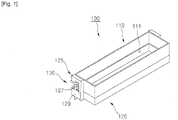
- Fig. 1 is a perspective view of a door basket according to an embodiment
- Fig. 2 is an exploded perspective view of the door basket according to an embodiment.
- a door basket 100 includes a basket body 110 and a basket support 120.
- the basket body 110 provides a space for receiving goods.
- the door basket 100 is detached from the basket support 120.
- the basket support 120 is movably disposed on the door 10 (see Fig. 3 ).
- a receiving space 111 is defined inside the basket body 110.
- the receiving space 111 is a space for receiving goods.
- the basket body 110 has an opened top surface with a polyhedral shape.
- the basket body 110 may have an opened top surface with a hexahedral shape.
- At least one portion of the basket body 110 may be formed of a transparent or translucent material to easily indentify goods received therein.
- a hook 113 is disposed on a circumference surface of the basket body 110.
- the hook 113 is defined by an outwardly stepped portion between an upper portion of the circumference surface of the basket body 110 and a lower portion of the circumference surface.
- the hook 113 is closely attached to an upper end of the circumference surface of the basket support 120 in a state where the basket body 110 is mounted on the basket support 120.
- a seat space 121 is defined in the basket support 120.
- the seat space 121 provides a space in which the basket body 110 detachably disposed on the basket support is seated.
- the basket support 120 has an opened top surface with a polyhedral shape.
- the seat space 121 is defined in the basket support 120.
- a circumference surface of the basket support 120 may have a height relatively higher than that of the basket body 110.
- the circumference and bottom surfaces of the basket support 120 are closely attached to those of the basket body 110 seated in the seat space 121, respectively. As described above, an upper end of the circumference of the basket support 120 is closely attached to the hook 113.
- An installation bracket 123 is disposed on a rear end of each of both circumference surfaces of the basket support 120.
- the installation bracket 123 is lengthily vertically disposed on each of both circumference surfaces of the basket support 120.
- the installation bracket 123 may have a height less than that of the basket body 110.
- the installation bracket 123 includes first and second stoppers 124A and 124B.
- the first and second stoppers 124A and 124B delimit a range of the rotation of a stopping lever 130.
- the first stopper 124A is disposed above the second stopper 124B.
- the stopping lever 130 is rotated along a predetermined trace within a region corresponding between the first and second stoppers 124A and 124B.
- the installation bracket 123 includes a guide protrusion 125.
- the guide protrusion 125 protrudes backward from a rear end of the installation bracket 123.
- the guide protrusion 125 is moved along a guide slot 11 (see Fig. 3 ) that will be described later in a state where the guide protrusion 125 is inserted into the guide slot 11.
- the guide protrusion 125 has a diameter (a left/right width in case where the guide protrusion does not have a circular shape) less than a left/right width of the guide slot 11.
- a hook rib 126 is disposed on a rear end of the guide protrusion 125.
- the hook rib 126 prevents the guide protrusion 125 from being arbitrarily separated from the guide slot 11 in the state where the guide protrusion 125 is inserted into the guide slot 11.
- the hook rib 126 radially extends from the rear end of the guide protrusion 125.
- the hook rib 126 may have a diameter greater than the left/right width of the guide slot 11.
- the installation bracket 123 includes first and second protrusions 127 and 128.
- the first and second protrusions 127 and 128 are spaced apart from each other.
- the first and second protrusions 127 and 128 protrude outward from one surface of the installation bracket 123.
- the stopping lever 130 and an elastic member 140 are disposed on the first and second protrusions 127 and 128, respectively.
- a cover member 129 is fixed to the installation bracket 123.
- the cover member 129 is fixed to the installation bracket 123 so that one surface of the cover member 129 is closely attached to front ends of the first and second protrusions 127 and 128.
- the cover member 129 prevents the stopping lever 130 and the elastic member 140 from being separated from the first and second protrusions 127 and 128.
- the stopping lever 130 is disposed on the installation bracket 123.
- the stopping lever 130 is rotatably disposed with respect to the first protrusion 127.
- a rotation range of the stopping lever 130 rotated with respect to the first protrusion 127 is delimited by the first and second stoppers 124A and 124B.
- the stopping lever 130 includes a lever body 131, a fixing part 133, and a manipulation part 135.
- an insertion hole 132 is defined in the lever body 131.
- the first protrusion 127 is inserted into the insertion hole 132.
- the lever body 131 is rotated with respect to the first protrusion 127 inserted into the insertion hole 132.
- the lever body 131 has an approximately ring shape.
- the fixing part 133 extends backward from a side of the lever body 131.
- a front end of the fixing part 133 protrudes toward a rear side of the basket support 120.
- the front end of the fixing part 133 protruding in a rear direction of the basket support 120 is substantially disposed directly under the guide protrusion 125.
- the fixing part 133 is substantially inserted into a fixing groove 15 (see Fig. 4 ) defined inside the guide slot 11.
- the fixing part 133 may be rotated between a position at which the fixing part 133 protrudes toward the rear side of the basket support 120 and a position at which the fixing part 133 is disposed within the installation bracket 123 by the rotation of the lever body 131.
- the fixing part 133 is rotated between a position at which a top surface of the fixing part 133 is closely attached to the first stopper 124A and a position at which a bottom surface of the fixing part 133 is closely attached to the second stopper 124B.
- An inclined guide surface 134 is disposed on the top surface of the fixing part 133.
- the top surface of the fixing part 133 is inclined downward toward the front end of the fixing part 133 to define the inclined guide surface 134.
- the inclined guide surface 134 prevents the fixing part 133 and the fixing groove 15 from interfering with respect to each other when the door basket 100, substantially, the basket support 120 is moved upward along the guide slot 11.
- the manipulation part 135 extends from a side of the lever body 131. Here, a front end of the manipulation part 135 protrudes toward a lower side of the basket support 120.
- the manipulation part 135 may be a portion which is pulled by a user to rotate the stopping lever 130. In more detail, when the manipulation part 135 is pulled, the stopping lever 130 is rotated with respect to the first protrusion 127 by overcoming an elastic force of the elastic member 140.
- the elastic member 140 applies an elastic force to the stopping lever 130.
- the elastic member 140 applies an elastic force to the stopping lever 130 so that the fixing part 133 extends in a rear direction of the basket support 120 and is inserted into the fixing groove 15.
- a torsion spring of which both ends are respectively supported by a side of the installation bracket 123 and the stopping lever 130, substantially, the manipulation part 135 in a state where the torsion spring is inserted into the second protrusion 128 may be used as the elastic member 140.
- the torsion spring applies an elastic force to the stopping lever 130 so that the fixing part 133 protrudes in the rear direction of the basket support 120, i.e., the fixing part 133 is inserted into the fixing groove 15.
- Fig. 3 is a perspective view illustrating a back surface of a door on which the door basket is installed according to an embodiment.
- Fig. 4 is a cross-sectional view illustrating a main part of the door according to an embodiment.
- two guide slots 11 are defined in a back surface of a door 10 for selectively opening or closing a storage space. Portions of both side ends of the back surface of the door 10 are lengthily cut in a vertical direction to define the guide slots 11, respectively.
- a distance between the guide slots 11 may be equal to that between the guide protrusions 125 and that between the fixing parts 133.
- the guide slot 11 substantially guides a vertical movement of the door basket 100. Substantially, a portion of the back surface of the door 10 is recessed into the inside of the door 10 to define the guide slot 11.
- a fixing member 13 is disposed within the door 10.
- the fixing member 13 is disposed on each of both inner side ends of the door 10 corresponding to the guide slot 11.
- the plurality of fixing groves 15 are defined in the fixing member 13.
- Each of the fixing grooves 15 is defined by cutting a portion of the fixing member 13.
- the fixing grooves 15 are vertically disposed spaced a predetermined distance from each other.
- the fixing part 133 is selectively inserted into the fixing groove 15.
- the fixing groove 15 may have a vertical height at least greater than a height of the fixing part 133.
- the guide protrusion 125 and the fixing part 133 are inserted into the guide slot 11. Also, in the state where the guide protrusion 125 is inserted into the guide slot 11, the hook rib 126 is hooked on the back surface of the door 10 adjacent to the guide slot 11. Thus, it may prevent the guide protrusion 125 from being arbitrarily separated from the guide slot 11. Also, the fixing part 133 is inserted into one of the fixing grooves 15. Also, the fixing part 133 is not arbitrarily separated from the fixing groove 15 by the elastic force applied into the stopping lever 130 from the elastic member 140 in the state where the fixing part 133 is inserted into the fixing groove 15.
- Figs. 5 to 8 are views illustrating a moving process of the door basket according to an embodiment.
- the guide protrusion 125 is inserted into the guide slot 11.
- the guide protrusion 125 is not arbitrarily separated from the guide slot 11 by the hook rib 126 hooked on the inside of the back surface of the door 10 adjacent to the guide slot 11.
- the fixing part 133 is inserted into one (hereinafter, for convenience of description, referred to as the "first fixing groove 15A") of the fixing grooves 15.
- the elastic member 140 applies an elastic force into the stopping lever 130 so that the fixing part 133 protrudes in the rear direction of the basket support 120 to maintain a state in which the fixing part 133 is inserted into the first fixing groove 15A.
- the stopping lever 130 is not rotated ever by the elastic force applied from the elastic member 140.
- a user pulls the manipulation part 135.
- the stopping lever 130 is rotated with respect to the first protrusion 127 by overcoming an elastic force of the elastic member 140.
- the fixing part 133 is separated from the first fixing groove 15A and disposed inside the installation bracket 123.
- the rotation of the stopping lever 130 may be performed until the fixing part 133 is closely attached to the second stopper 124B.
- the door basket 100 is moved downward so that the door basket 100 is disposed at a predetermined position.
- the fixing part 133 is disposed within the installation bracket 123, the door basket 100 does not interfere with the fixing part 133 and the fixing groove 15 or/and the fixing member 13 during the movement thereof.
- the stopping lever 130 is rotated by the elastic force by the elastic member 140 to allow the fixing part 133 to protrude in the rear direction of the basket support 120, thereby inserting the fixing part 133 into the other fixing groove (hereinafter, for convenience of description, referred to as the "second fixing groove 15B") of the fixing grooves 15.
- the door basket 100 may be maintained in the state where the door basket 100 is mounted on the bask surface of the door 10 at a height corresponding to the second fixing groove 15B.
- a third fixing groove 15C a height corresponding to the other fixing groove disposed above the first fixing groove 15A
- an external force pushing the fixing part 133 is substantially removed.
- the stopping lever 130 is rotated by the elastic force of the elastic member 140.
- the stopping lever 130 since the stopping lever 130 is rotated to insert the fixing part 133 into the third fixing groove 15C, the door basket 100 may be maintained in a state where the door basket 100 is mounted on the bask surface of the door 100 at the height corresponding to the third fixing groove 15C.
- the user may separate the basket body 110 from the basket support 120.
- goods may be more easily received into the basket body 110, i.e., the receiving space 111.
- the torsion spring is described as an example of the elastic member, different types of springs or members may be used as the elastic member.
- a coil spring of which both ends are respectively fixed to a side of the installation bracket and a side of the stopping lever may be used as the elastic member.
- the door basket can be easily varied in position according to heights of goods received in the door basket. Also, since the door basket can be easily detached from the door, the user may more easily take in or out the goods received in the door basket.
Landscapes
- Engineering & Computer Science (AREA)
- Chemical & Material Sciences (AREA)
- Combustion & Propulsion (AREA)
- Physics & Mathematics (AREA)
- Mechanical Engineering (AREA)
- Thermal Sciences (AREA)
- General Engineering & Computer Science (AREA)
- Refrigerator Housings (AREA)
Claims (9)
- Kühlschranktür (10), die aufweist:einen Türkorb (100), der auf einer Rückseite der Tür (10) zum selektiven Öffnen oder Schließen eines Aufbewahrungsraums angeordnet ist und beweglich an der Rückseite der Tür (10) angebracht ist, die ein Paar Führungsschlitze (11) aufweist, um die Höhe einer Befestigungsposition einzustellen, wobei der Türkorb (100) aufweist:einen Korbkörper (110), der Waren aufnimmt;einen Korbträger (120) mit einer offenen Oberseite mit einer polyedrischen Form, um einen Aufnahmeraum (121) zu definieren, der einen Raum bereitstellt, in dem der Korbkörper (110) abnehmbar am Korbträger (120) angeordnet ist;einen Haken (113), der durch einen nach außen abgestuften Abschnitt zwischen einem oberen Abschnitt einer Umfangsfläche des Korbkörpers (110) und einem unteren Abschnitt einer Umfangsfläche des Korbkörpers (110) definiert ist;eine Installationshalterung (123), die an einem hinteren Ende von jeweils beiden Umfangsflächen des Korbträgers (120) angeordnet ist;einen Fixierhebel (130), der drehbar an der Installationshalterung (123) an einer Position angeordnet ist, die einer von mehreren Fixiernuten (15) entspricht, die in der Rückseite der Tür (10) vertikal voneinander beabstandet sind;einen Führungsvorsprung (125), der aus der Installationshalterung (123) vorsteht und konfiguriert ist, sich längs des Paars der Führungsschlitze (11) zu bewegen, die in einer vertikalen Richtung an derselben Position wie die Fixiernuten (15) länglich eingeschnitten sind; undein elastisches Element (140), das eine Federkraft auf den Fixierhebel (130) ausübt, so dass der Fixierhebel (130) in einem Zustand gehalten wird, in dem der Fixierhebel (130) in eine der Fixiernuten (15) eingesetzt ist,wobei ein Abstand zwischen dem Paar der Führungsschlitze (11) gleich dem zwischen dem Führungsvorsprung (125) und dem zwischen den Fixiernuten (15) ist, undwobei der Haken (113) in einem Zustand, in dem der Korbkörper (110) am Korbträger befestigt ist, eng an einem oberen Ende der Umfangsfläche des Korbträgers (120) angebracht ist.
- Kühlschranktür (10) nach Anspruch 1, wobei der Fixierhebel (130) aufweist:einen Hebelkörper (131), der in Bezug auf einen am Korbträger (120) angeordneten Vorsprung drehbar angeordnet ist;einen Fixierteil (133), der sich vom Hebelkörper (131) erstreckt, wobei der Fixierteil (133) selektiv in die Fixiernuten (15) eingesetzt ist; undeinen Bedienungsteil (135), der durch einen Benutzer bedient wird, um den Hebelkörper (131) zu drehen.
- Kühlschranktür (10) nach Anspruch 2, wobei eine geneigte Führungsfläche (134), um zu verhindern, dass sich der Fixierteil (133) und die Fixiernuten (15) gegenseitig stören, wenn der Korbträger (120) längs der Führungsschlitze (11) nach oben bewegt wird, an einer Oberseite des Fixierteils (133) angeordnet ist.
- Kühlschranktür (10) nach Anspruch 1, wobei ein Stopper zum Begrenzen eines Drehbereichs des Fixierhebels (130) an der Installationshalterung angeordnet ist.
- Kühlschranktür (10) nach Anspruch 4, wobei der Stopper aufweist:einen ersten Stopper (124A) zum Begrenzen eines maximalen Drehbereichs des Fixierhebels (130) in einer Richtung, in der der Fixierhebel (130) in eine der Fixiernuten (15) eingesetzt wird; undeinen zweiten Stopper (124B) zum Begrenzen des maximalen Drehbereichs des Fixierhebels (130) in einer Richtung, in der der Fixierhebel (130) von einer der Fixiernuten (15) getrennt wird.
- Kühlschranktür (10) nach Anspruch 1, wobei das elastische Element (140) eine Torsionsfeder aufweist, die an der Installationshalterung (123) angeordnet ist, und von der beide Enden eng an einer Seite der Installationshalterung (123) bzw. einer Seite des Fixierhebels (130) angebracht sind.
- Kühlschranktür (10) nach Anspruch 6, die ferner ein Abdeckelement (129) zum Abdecken der Installationshalterung (123) aufweist, um zu verhindern, dass der Fixierhebel (130) und das elastische Element (140) in einem Zustand, in dem der Fixierhebel (130) und das elastische Element (140) an der Installationshalterung (123) befestigt sind, willkürlich getrennt werden.
- Kühlschranktür (10) nach Anspruch 1, wobei sich mindestens ein Abschnitt des am Korbträger (120) angeordneten Führungsvorsprungs (125) mit einer der mehreren Fixiernuten (15) überlappt, wodurch er längs der Führungsschlitze (11) bewegt wird.
- Kühlschranktür (10) nach Anspruch 8, wobei eine Hakenrippe (126) an einem hinteren Ende des Führungsvorsprungs (125) angeordnet ist, die einen Durchmesser aufweist, der größer als die linke/rechte Breite der Führungsschlitze (11) ist, um zu verhindern, dass der Führungsvorsprung willkürlich von den Führungsschlitzen (11) getrennt wird.
Applications Claiming Priority (2)
| Application Number | Priority Date | Filing Date | Title |
|---|---|---|---|
| KR1020100009339A KR20110089792A (ko) | 2010-02-01 | 2010-02-01 | 도어 바스켓 및 이를 포함하는 냉장고 |
| PCT/KR2010/007419 WO2011093577A1 (ko) | 2010-02-01 | 2010-10-27 | 도어 바스켓 및 이를 포함하는 냉장고 |
Publications (3)
| Publication Number | Publication Date |
|---|---|
| EP2532996A1 EP2532996A1 (de) | 2012-12-12 |
| EP2532996A4 EP2532996A4 (de) | 2014-07-16 |
| EP2532996B1 true EP2532996B1 (de) | 2021-09-15 |
Family
ID=44319531
Family Applications (1)
| Application Number | Title | Priority Date | Filing Date |
|---|---|---|---|
| EP10844801.0A Active EP2532996B1 (de) | 2010-02-01 | 2010-10-27 | Kühlschranktür mit Türkorb |
Country Status (4)
| Country | Link |
|---|---|
| US (1) | US20120293056A1 (de) |
| EP (1) | EP2532996B1 (de) |
| KR (1) | KR20110089792A (de) |
| WO (1) | WO2011093577A1 (de) |
Families Citing this family (29)
| Publication number | Priority date | Publication date | Assignee | Title |
|---|---|---|---|---|
| EP2410270B1 (de) * | 2010-07-20 | 2022-09-07 | Lg Electronics Inc. | Kühlschrank |
| KR101884349B1 (ko) * | 2011-11-18 | 2018-08-30 | 엘지전자 주식회사 | 냉장고 |
| KR101869556B1 (ko) * | 2011-11-15 | 2018-06-21 | 엘지전자 주식회사 | 냉장고 |
| US9429355B2 (en) | 2011-11-15 | 2016-08-30 | Lg Electronics Inc. | Refrigerator |
| KR20130060864A (ko) * | 2011-11-30 | 2013-06-10 | 엘지전자 주식회사 | 냉장고 |
| KR101860713B1 (ko) * | 2013-02-23 | 2018-05-24 | 삼성전자주식회사 | 슬라이딩 장치 및 이를 갖는 냉장고 |
| CN104374148A (zh) * | 2013-08-12 | 2015-02-25 | 海尔集团公司 | 用于调节冰箱内活动部件的限位孔 |
| CN104374149B (zh) * | 2013-08-12 | 2016-11-23 | 海尔集团公司 | 冰箱内活动部件的调节方法 |
| CN103776230B (zh) * | 2014-01-26 | 2016-03-30 | 合肥晶弘电器有限公司 | 一种带有储物盒的冰箱 |
| CN104006619B (zh) * | 2014-05-14 | 2016-09-21 | 海信容声(广东)冰箱有限公司 | 一种冰箱 |
| CN104006620B (zh) * | 2014-05-14 | 2016-03-23 | 海信容声(广东)冰箱有限公司 | 一种冰箱 |
| US9468313B2 (en) * | 2014-10-03 | 2016-10-18 | ATA Retail Services, Inc. | Product display tray |
| KR101646514B1 (ko) * | 2014-10-15 | 2016-08-08 | 엘지전자 주식회사 | 냉장고 |
| KR102396040B1 (ko) * | 2016-01-05 | 2022-05-10 | 엘지전자 주식회사 | 냉장고 |
| KR102388156B1 (ko) | 2015-12-03 | 2022-04-19 | 삼성전자주식회사 | 도어가드 어셈블리 및 이를 갖는 냉장고 |
| KR20170114580A (ko) | 2016-04-05 | 2017-10-16 | 엘지전자 주식회사 | 냉장고 |
| KR102463798B1 (ko) * | 2016-05-12 | 2022-11-07 | 엘지전자 주식회사 | 냉장고 |
| US9863690B1 (en) * | 2016-11-23 | 2018-01-09 | Bsh Hausgeraete Gmbh | Home appliance door |
| DE102017216288A1 (de) * | 2017-09-14 | 2019-03-14 | BSH Hausgeräte GmbH | Türabsteller für ein Kältegerät |
| CN108278845A (zh) * | 2018-03-27 | 2018-07-13 | 泰州乐金电子冷机有限公司 | 可调节空间的冰箱门中门 |
| KR102456241B1 (ko) * | 2018-05-18 | 2022-10-19 | 엘지전자 주식회사 | 냉장고 |
| JP7197724B2 (ja) * | 2019-01-12 | 2022-12-27 | 中山市海楽電器有限公司 | 冷蔵キャビネットの棚のスライド調整用の支持フレーム |
| DE102019115617A1 (de) * | 2019-05-21 | 2020-11-26 | Liebherr-Hausgeräte Ochsenhausen GmbH | Kühl- und/oder Gefriergerät mit höhenverstellbarem Türabsteller |
| US11448457B2 (en) | 2019-12-19 | 2022-09-20 | Midea Group Co., Ltd. | Refrigerator with an adjustable bin |
| US10962279B1 (en) * | 2019-12-19 | 2021-03-30 | Midea Group Co., Ltd. | Refrigerator with an adjustable bin |
| US12031769B2 (en) * | 2021-09-15 | 2024-07-09 | Whirlpool Corporation | Attachment assembly for an insulated door |
| US11629904B1 (en) * | 2022-01-12 | 2023-04-18 | Bby Solutions, Inc. | Adjustable refrigerator shelving |
| US12031770B2 (en) * | 2022-02-15 | 2024-07-09 | Whirlpool Corporation | Storage assembly for an appliance |
| US12535260B2 (en) * | 2023-11-21 | 2026-01-27 | Whirlpool Corporation | Trimbreaker ladder cover |
Family Cites Families (23)
| Publication number | Priority date | Publication date | Assignee | Title |
|---|---|---|---|---|
| US3269556A (en) * | 1964-05-06 | 1966-08-30 | Streater Ind Inc | Collapsible support structure |
| US3469711A (en) * | 1967-10-23 | 1969-09-30 | Westinghouse Electric Corp | Shelf construction for refrigerator door |
| US3610174A (en) * | 1969-10-08 | 1971-10-05 | Gen Motors Corp | Infinite adjustable door shelf |
| US3647075A (en) * | 1970-04-30 | 1972-03-07 | Westinghouse Electric Corp | Shelf construction for a refrigerator door |
| US4174486A (en) * | 1977-12-02 | 1979-11-13 | Winkler Clifford W | Adjustable shelving system |
| US5338137A (en) * | 1992-02-28 | 1994-08-16 | Jensen Richard H | Adjustable decking system for use in supporting freight in a compartment |
| KR100302905B1 (ko) * | 1998-02-05 | 2001-11-22 | 윤종용 | 냉장고의도어 |
| US6062780A (en) * | 1998-04-09 | 2000-05-16 | Petelka; Brian W. | Adjustable decking system |
| US6074143A (en) * | 1999-04-27 | 2000-06-13 | Ancra International Llc | Adjustable decking system for supporting freight |
| US6497185B1 (en) * | 2000-08-22 | 2002-12-24 | L&P Property Management Company | Slidable unit for modular shelving system |
| US6739811B1 (en) * | 2002-12-19 | 2004-05-25 | Aero-Kit Industries Inc. | Deck beam and support rail |
| KR100508477B1 (ko) * | 2003-01-27 | 2005-08-17 | 삼성전자주식회사 | 냉장고 |
| KR20050003863A (ko) * | 2003-07-04 | 2005-01-12 | 엘지전자 주식회사 | 냉장고 도어바스켓의 높이조절장치 |
| KR100953977B1 (ko) * | 2003-10-04 | 2010-04-21 | 엘지전자 주식회사 | 냉장고용 도어바스켓 |
| KR100766565B1 (ko) * | 2005-12-12 | 2007-10-11 | 엘지전자 주식회사 | 냉장고용 도어바스켓 |
| US7748805B2 (en) * | 2006-01-11 | 2010-07-06 | Whirlpool Corporation | Means for providing adjustment to bins and shelves in refrigerators |
| KR100833370B1 (ko) * | 2006-11-20 | 2008-05-28 | 엘지전자 주식회사 | 냉장고 선반의 높이조절 구조 |
| DE102006061152A1 (de) * | 2006-12-22 | 2008-06-26 | BSH Bosch und Siemens Hausgeräte GmbH | Kältegerät |
| KR20080065859A (ko) * | 2007-01-10 | 2008-07-15 | 엘지전자 주식회사 | 냉장고용 도어바스켓 |
| DE102007005951A1 (de) * | 2007-02-06 | 2008-08-07 | BSH Bosch und Siemens Hausgeräte GmbH | Butterfach für ein Kältegerät |
| DE202007013356U1 (de) * | 2007-05-31 | 2008-10-09 | Liebherr-Hausgeräte Ochsenhausen GmbH | Vorrichtung zur Verstellung eines Bodens oder Abstellers eines Kühl- und/oder Gefriergerätes |
| DE102008014885A1 (de) * | 2008-03-19 | 2009-09-24 | BSH Bosch und Siemens Hausgeräte GmbH | Kältegerät und zugehörige Rastmittelanordnung zum nachträglichen Anbau |
| EP2410270B1 (de) * | 2010-07-20 | 2022-09-07 | Lg Electronics Inc. | Kühlschrank |
-
2010
- 2010-02-01 KR KR1020100009339A patent/KR20110089792A/ko not_active Ceased
- 2010-10-27 EP EP10844801.0A patent/EP2532996B1/de active Active
- 2010-10-27 WO PCT/KR2010/007419 patent/WO2011093577A1/ko not_active Ceased
- 2010-10-27 US US13/576,226 patent/US20120293056A1/en not_active Abandoned
Also Published As
| Publication number | Publication date |
|---|---|
| US20120293056A1 (en) | 2012-11-22 |
| KR20110089792A (ko) | 2011-08-09 |
| EP2532996A4 (de) | 2014-07-16 |
| WO2011093577A1 (ko) | 2011-08-04 |
| EP2532996A1 (de) | 2012-12-12 |
Similar Documents
| Publication | Publication Date | Title |
|---|---|---|
| EP2532996B1 (de) | Kühlschranktür mit Türkorb | |
| EP2886982B1 (de) | Kühlschrank | |
| US8052236B2 (en) | Refrigerator | |
| EP2940411B1 (de) | Kühlschrank | |
| KR101618128B1 (ko) | 냉장고 | |
| KR102186243B1 (ko) | 냉장고 | |
| KR102463798B1 (ko) | 냉장고 | |
| EP3150946B1 (de) | Kühlschrank mit verriegelungsvorrichtung für Eiskübel und Verfahren zur Installation der Verriegelungsvorrichtung für den Eiskübel | |
| EP3674640B1 (de) | Kühlschrank | |
| EP3209959B1 (de) | Kühlschrank | |
| EP2792978B1 (de) | Lebensmittelbehälter | |
| US20180202707A1 (en) | Refrigerator and door opening and closing apparatus for refrigerator | |
| EP2225510A1 (de) | Kühlvorrichtung | |
| EP3770538A1 (de) | Kühlschrank | |
| JP2012037158A (ja) | 貯蔵庫 | |
| KR20060081923A (ko) | 냉장고 | |
| KR101869556B1 (ko) | 냉장고 | |
| US10041727B2 (en) | Refrigerator having locking device for ice bucket and method for installing locking device for ice bucket | |
| KR102004434B1 (ko) | 냉장고 | |
| KR102004446B1 (ko) | 냉장고 | |
| EP3150945B1 (de) | Kühlschrank mit verriegelungsvorrichtung für eiskübel und verfahren zur installation der verriegelungsvorrichtung eines eiskübels | |
| KR20070102872A (ko) | 냉장고용 도어바스켓 | |
| CN121630169A (zh) | 家电产品 |
Legal Events
| Date | Code | Title | Description |
|---|---|---|---|
| PUAI | Public reference made under article 153(3) epc to a published international application that has entered the european phase |
Free format text: ORIGINAL CODE: 0009012 |
|
| 17P | Request for examination filed |
Effective date: 20120829 |
|
| AK | Designated contracting states |
Kind code of ref document: A1 Designated state(s): AL AT BE BG CH CY CZ DE DK EE ES FI FR GB GR HR HU IE IS IT LI LT LU LV MC MK MT NL NO PL PT RO RS SE SI SK SM TR |
|
| DAX | Request for extension of the european patent (deleted) | ||
| A4 | Supplementary search report drawn up and despatched |
Effective date: 20140616 |
|
| RIC1 | Information provided on ipc code assigned before grant |
Ipc: F25D 23/04 20060101AFI20140610BHEP |
|
| STAA | Information on the status of an ep patent application or granted ep patent |
Free format text: STATUS: EXAMINATION IS IN PROGRESS |
|
| 17Q | First examination report despatched |
Effective date: 20171113 |
|
| RIC1 | Information provided on ipc code assigned before grant |
Ipc: A47B 96/16 20060101ALI20180316BHEP Ipc: F25D 23/04 20060101AFI20180316BHEP |
|
| GRAP | Despatch of communication of intention to grant a patent |
Free format text: ORIGINAL CODE: EPIDOSNIGR1 |
|
| STAA | Information on the status of an ep patent application or granted ep patent |
Free format text: STATUS: GRANT OF PATENT IS INTENDED |
|
| INTG | Intention to grant announced |
Effective date: 20210407 |
|
| GRAS | Grant fee paid |
Free format text: ORIGINAL CODE: EPIDOSNIGR3 |
|
| GRAA | (expected) grant |
Free format text: ORIGINAL CODE: 0009210 |
|
| STAA | Information on the status of an ep patent application or granted ep patent |
Free format text: STATUS: THE PATENT HAS BEEN GRANTED |
|
| AK | Designated contracting states |
Kind code of ref document: B1 Designated state(s): AL AT BE BG CH CY CZ DE DK EE ES FI FR GB GR HR HU IE IS IT LI LT LU LV MC MK MT NL NO PL PT RO RS SE SI SK SM TR |
|
| REG | Reference to a national code |
Ref country code: CH Ref legal event code: EP Ref country code: GB Ref legal event code: FG4D |
|
| REG | Reference to a national code |
Ref country code: DE Ref legal event code: R096 Ref document number: 602010067593 Country of ref document: DE |
|
| REG | Reference to a national code |
Ref country code: IE Ref legal event code: FG4D |
|
| REG | Reference to a national code |
Ref country code: AT Ref legal event code: REF Ref document number: 1430819 Country of ref document: AT Kind code of ref document: T Effective date: 20211015 |
|
| REG | Reference to a national code |
Ref country code: LT Ref legal event code: MG9D |
|
| REG | Reference to a national code |
Ref country code: NL Ref legal event code: MP Effective date: 20210915 |
|
| PG25 | Lapsed in a contracting state [announced via postgrant information from national office to epo] |
Ref country code: HR Free format text: LAPSE BECAUSE OF FAILURE TO SUBMIT A TRANSLATION OF THE DESCRIPTION OR TO PAY THE FEE WITHIN THE PRESCRIBED TIME-LIMIT Effective date: 20210915 Ref country code: SE Free format text: LAPSE BECAUSE OF FAILURE TO SUBMIT A TRANSLATION OF THE DESCRIPTION OR TO PAY THE FEE WITHIN THE PRESCRIBED TIME-LIMIT Effective date: 20210915 Ref country code: RS Free format text: LAPSE BECAUSE OF FAILURE TO SUBMIT A TRANSLATION OF THE DESCRIPTION OR TO PAY THE FEE WITHIN THE PRESCRIBED TIME-LIMIT Effective date: 20210915 Ref country code: NO Free format text: LAPSE BECAUSE OF FAILURE TO SUBMIT A TRANSLATION OF THE DESCRIPTION OR TO PAY THE FEE WITHIN THE PRESCRIBED TIME-LIMIT Effective date: 20211215 Ref country code: FI Free format text: LAPSE BECAUSE OF FAILURE TO SUBMIT A TRANSLATION OF THE DESCRIPTION OR TO PAY THE FEE WITHIN THE PRESCRIBED TIME-LIMIT Effective date: 20210915 Ref country code: BG Free format text: LAPSE BECAUSE OF FAILURE TO SUBMIT A TRANSLATION OF THE DESCRIPTION OR TO PAY THE FEE WITHIN THE PRESCRIBED TIME-LIMIT Effective date: 20211215 Ref country code: LT Free format text: LAPSE BECAUSE OF FAILURE TO SUBMIT A TRANSLATION OF THE DESCRIPTION OR TO PAY THE FEE WITHIN THE PRESCRIBED TIME-LIMIT Effective date: 20210915 |
|
| REG | Reference to a national code |
Ref country code: AT Ref legal event code: MK05 Ref document number: 1430819 Country of ref document: AT Kind code of ref document: T Effective date: 20210915 |
|
| PG25 | Lapsed in a contracting state [announced via postgrant information from national office to epo] |
Ref country code: LV Free format text: LAPSE BECAUSE OF FAILURE TO SUBMIT A TRANSLATION OF THE DESCRIPTION OR TO PAY THE FEE WITHIN THE PRESCRIBED TIME-LIMIT Effective date: 20210915 Ref country code: GR Free format text: LAPSE BECAUSE OF FAILURE TO SUBMIT A TRANSLATION OF THE DESCRIPTION OR TO PAY THE FEE WITHIN THE PRESCRIBED TIME-LIMIT Effective date: 20211216 |
|
| PG25 | Lapsed in a contracting state [announced via postgrant information from national office to epo] |
Ref country code: AT Free format text: LAPSE BECAUSE OF FAILURE TO SUBMIT A TRANSLATION OF THE DESCRIPTION OR TO PAY THE FEE WITHIN THE PRESCRIBED TIME-LIMIT Effective date: 20210915 |
|
| REG | Reference to a national code |
Ref country code: CH Ref legal event code: PL |
|
| PG25 | Lapsed in a contracting state [announced via postgrant information from national office to epo] |
Ref country code: IS Free format text: LAPSE BECAUSE OF FAILURE TO SUBMIT A TRANSLATION OF THE DESCRIPTION OR TO PAY THE FEE WITHIN THE PRESCRIBED TIME-LIMIT Effective date: 20220115 Ref country code: SM Free format text: LAPSE BECAUSE OF FAILURE TO SUBMIT A TRANSLATION OF THE DESCRIPTION OR TO PAY THE FEE WITHIN THE PRESCRIBED TIME-LIMIT Effective date: 20210915 Ref country code: SK Free format text: LAPSE BECAUSE OF FAILURE TO SUBMIT A TRANSLATION OF THE DESCRIPTION OR TO PAY THE FEE WITHIN THE PRESCRIBED TIME-LIMIT Effective date: 20210915 Ref country code: RO Free format text: LAPSE BECAUSE OF FAILURE TO SUBMIT A TRANSLATION OF THE DESCRIPTION OR TO PAY THE FEE WITHIN THE PRESCRIBED TIME-LIMIT Effective date: 20210915 Ref country code: PT Free format text: LAPSE BECAUSE OF FAILURE TO SUBMIT A TRANSLATION OF THE DESCRIPTION OR TO PAY THE FEE WITHIN THE PRESCRIBED TIME-LIMIT Effective date: 20220117 Ref country code: PL Free format text: LAPSE BECAUSE OF FAILURE TO SUBMIT A TRANSLATION OF THE DESCRIPTION OR TO PAY THE FEE WITHIN THE PRESCRIBED TIME-LIMIT Effective date: 20210915 Ref country code: NL Free format text: LAPSE BECAUSE OF FAILURE TO SUBMIT A TRANSLATION OF THE DESCRIPTION OR TO PAY THE FEE WITHIN THE PRESCRIBED TIME-LIMIT Effective date: 20210915 Ref country code: ES Free format text: LAPSE BECAUSE OF FAILURE TO SUBMIT A TRANSLATION OF THE DESCRIPTION OR TO PAY THE FEE WITHIN THE PRESCRIBED TIME-LIMIT Effective date: 20210915 Ref country code: EE Free format text: LAPSE BECAUSE OF FAILURE TO SUBMIT A TRANSLATION OF THE DESCRIPTION OR TO PAY THE FEE WITHIN THE PRESCRIBED TIME-LIMIT Effective date: 20210915 Ref country code: CZ Free format text: LAPSE BECAUSE OF FAILURE TO SUBMIT A TRANSLATION OF THE DESCRIPTION OR TO PAY THE FEE WITHIN THE PRESCRIBED TIME-LIMIT Effective date: 20210915 Ref country code: AL Free format text: LAPSE BECAUSE OF FAILURE TO SUBMIT A TRANSLATION OF THE DESCRIPTION OR TO PAY THE FEE WITHIN THE PRESCRIBED TIME-LIMIT Effective date: 20210915 |
|
| REG | Reference to a national code |
Ref country code: DE Ref legal event code: R097 Ref document number: 602010067593 Country of ref document: DE |
|
| REG | Reference to a national code |
Ref country code: BE Ref legal event code: MM Effective date: 20211031 |
|
| PG25 | Lapsed in a contracting state [announced via postgrant information from national office to epo] |
Ref country code: MC Free format text: LAPSE BECAUSE OF FAILURE TO SUBMIT A TRANSLATION OF THE DESCRIPTION OR TO PAY THE FEE WITHIN THE PRESCRIBED TIME-LIMIT Effective date: 20210915 |
|
| PLBE | No opposition filed within time limit |
Free format text: ORIGINAL CODE: 0009261 |
|
| STAA | Information on the status of an ep patent application or granted ep patent |
Free format text: STATUS: NO OPPOSITION FILED WITHIN TIME LIMIT |
|
| PG25 | Lapsed in a contracting state [announced via postgrant information from national office to epo] |
Ref country code: LU Free format text: LAPSE BECAUSE OF NON-PAYMENT OF DUE FEES Effective date: 20211027 Ref country code: DK Free format text: LAPSE BECAUSE OF FAILURE TO SUBMIT A TRANSLATION OF THE DESCRIPTION OR TO PAY THE FEE WITHIN THE PRESCRIBED TIME-LIMIT Effective date: 20210915 Ref country code: BE Free format text: LAPSE BECAUSE OF NON-PAYMENT OF DUE FEES Effective date: 20211031 |
|
| 26N | No opposition filed |
Effective date: 20220616 |
|
| PG25 | Lapsed in a contracting state [announced via postgrant information from national office to epo] |
Ref country code: SI Free format text: LAPSE BECAUSE OF FAILURE TO SUBMIT A TRANSLATION OF THE DESCRIPTION OR TO PAY THE FEE WITHIN THE PRESCRIBED TIME-LIMIT Effective date: 20210915 Ref country code: LI Free format text: LAPSE BECAUSE OF NON-PAYMENT OF DUE FEES Effective date: 20211031 Ref country code: CH Free format text: LAPSE BECAUSE OF NON-PAYMENT OF DUE FEES Effective date: 20211031 |
|
| PG25 | Lapsed in a contracting state [announced via postgrant information from national office to epo] |
Ref country code: IE Free format text: LAPSE BECAUSE OF NON-PAYMENT OF DUE FEES Effective date: 20211027 |
|
| PG25 | Lapsed in a contracting state [announced via postgrant information from national office to epo] |
Ref country code: FR Free format text: LAPSE BECAUSE OF NON-PAYMENT OF DUE FEES Effective date: 20211115 |
|
| PG25 | Lapsed in a contracting state [announced via postgrant information from national office to epo] |
Ref country code: IT Free format text: LAPSE BECAUSE OF FAILURE TO SUBMIT A TRANSLATION OF THE DESCRIPTION OR TO PAY THE FEE WITHIN THE PRESCRIBED TIME-LIMIT Effective date: 20210915 |
|
| PG25 | Lapsed in a contracting state [announced via postgrant information from national office to epo] |
Ref country code: HU Free format text: LAPSE BECAUSE OF FAILURE TO SUBMIT A TRANSLATION OF THE DESCRIPTION OR TO PAY THE FEE WITHIN THE PRESCRIBED TIME-LIMIT; INVALID AB INITIO Effective date: 20101027 Ref country code: CY Free format text: LAPSE BECAUSE OF FAILURE TO SUBMIT A TRANSLATION OF THE DESCRIPTION OR TO PAY THE FEE WITHIN THE PRESCRIBED TIME-LIMIT Effective date: 20210915 |
|
| PG25 | Lapsed in a contracting state [announced via postgrant information from national office to epo] |
Ref country code: MK Free format text: LAPSE BECAUSE OF FAILURE TO SUBMIT A TRANSLATION OF THE DESCRIPTION OR TO PAY THE FEE WITHIN THE PRESCRIBED TIME-LIMIT Effective date: 20210915 |
|
| PG25 | Lapsed in a contracting state [announced via postgrant information from national office to epo] |
Ref country code: TR Free format text: LAPSE BECAUSE OF FAILURE TO SUBMIT A TRANSLATION OF THE DESCRIPTION OR TO PAY THE FEE WITHIN THE PRESCRIBED TIME-LIMIT Effective date: 20210915 |
|
| PG25 | Lapsed in a contracting state [announced via postgrant information from national office to epo] |
Ref country code: MT Free format text: LAPSE BECAUSE OF FAILURE TO SUBMIT A TRANSLATION OF THE DESCRIPTION OR TO PAY THE FEE WITHIN THE PRESCRIBED TIME-LIMIT Effective date: 20210915 |
|
| PGFP | Annual fee paid to national office [announced via postgrant information from national office to epo] |
Ref country code: GB Payment date: 20240905 Year of fee payment: 15 |
|
| PGFP | Annual fee paid to national office [announced via postgrant information from national office to epo] |
Ref country code: DE Payment date: 20240905 Year of fee payment: 15 |