EP2533059A1 - Vorrichtung zur prüfung der intaktheit eines kabelbaums, programm zur prüfung der intaktheit eines kabelbaums und verfahren zur prüfung der intaktheit eines kabelbaums - Google Patents
Vorrichtung zur prüfung der intaktheit eines kabelbaums, programm zur prüfung der intaktheit eines kabelbaums und verfahren zur prüfung der intaktheit eines kabelbaums Download PDFInfo
- Publication number
- EP2533059A1 EP2533059A1 EP10834672A EP10834672A EP2533059A1 EP 2533059 A1 EP2533059 A1 EP 2533059A1 EP 10834672 A EP10834672 A EP 10834672A EP 10834672 A EP10834672 A EP 10834672A EP 2533059 A1 EP2533059 A1 EP 2533059A1
- Authority
- EP
- European Patent Office
- Prior art keywords
- inspection
- terminal
- connector
- electrical
- wire
- Prior art date
- Legal status (The legal status is an assumption and is not a legal conclusion. Google has not performed a legal analysis and makes no representation as to the accuracy of the status listed.)
- Granted
Links
Images











Classifications
-
- G—PHYSICS
- G01—MEASURING; TESTING
- G01R—MEASURING ELECTRIC VARIABLES; MEASURING MAGNETIC VARIABLES
- G01R31/00—Arrangements for testing electric properties; Arrangements for locating electric faults; Arrangements for electrical testing characterised by what is being tested not provided for elsewhere
- G01R31/50—Testing of electric apparatus, lines, cables or components for short-circuits, continuity, leakage current or incorrect line connections
- G01R31/58—Testing of lines, cables or conductors
-
- G—PHYSICS
- G06—COMPUTING OR CALCULATING; COUNTING
- G06F—ELECTRIC DIGITAL DATA PROCESSING
- G06F2113/00—Details relating to the application field
- G06F2113/16—Cables, cable trees or wire harnesses
Definitions
- the present invention relates to a wire harness continuity inspection device, a wire harness continuity inspection program, and a wire harness continuity inspection method for comparing connection between the starting point and the terminating point of a circuit line, described in auxiliary device-based wiring information (more specifically auxiliary device-based wiring information prepared for each grade of a vehicle model and depending on the presence of an optional function) including wiring information on electrical wires and connectors connected to an auxiliary device, prepared in relation to a certain vehicle model with connection of electrical wires described in region-based connector information including information on connectors constituting wire harnesses designed for each subdivided region and region-based wiring information including information on wirings constituting the wire harnesses designed for each subdivided region (the region-based connector information is an actual wiring diagram prepared based on the auxiliary device-based wiring information, and the region-based wiring information is a diagram expanded based on an auxiliary device specification table of the vehicle model; thereinafter, the region-based connector information and the region-based wiring information will be collectively referred to as "region-based connector/wir
- auxiliary device-based wiring information and an actual wiring diagram prepared based on the auxiliary device-based wiring information will be described.
- the auxiliary device-based wiring information and the actual wiring diagram have been designed by CAD (Computer Aided Design) (for example, see Patent Literature 1).
- the auxiliary device-based wiring information is prepared for each of the systems mounted in a vehicle and individually driven, such as a head lamp system, an airbag system, an air-conditioning system, an engine control system, and an ABS system.
- a head lamp system such as a head lamp system, an airbag system, an air-conditioning system, an engine control system, and an ABS system.
- electrical components for example, a battery, an ECU (Electronic Control Unit), and a driving machine constituting the system by a signal line, a power line, and a ground line.
- the auxiliary device-based wiring information includes circuit line connection information showing which terminals of which electrical component, the starting point and the terminating point of each of the electrical wires of these signal line, power line, and ground line are connected to, and which electrical wires the signal line, the power line, and the ground line are connected to, and auxiliary device information on an auxiliary device that connects the electrical wires of the signal line, the power line, and the ground line to the electrical component. Since the auxiliary device-based wiring information mainly aims to show a circuit diagram of a system made up of a plurality of electrical components, information on electrical wires is not included therein.
- an actual wiring diagram in which information on the electrical wires is added to the auxiliary device-based wiring information is prepared.
- the actual wiring diagram is one in which the information on the electrical wires is added to the information on the circuit lines connecting electrical components, described in the auxiliary device-based wiring information, and which is divided into respective regions (an engine compartment, a vehicle interior wall, or a trunk; hereinafter these regions will be referred to as subdivided regions) where wire harnesses can be arranged, dividing a vehicle space into respective functions.
- auxiliary device-based wiring information when a circuit line described in the auxiliary device-based wiring information extends over a plurality of subdivided regions to be connected to a plurality of electrical components, information on terminals or connectors connected to the terminals of the electrical component at the starting point and the terminating points of the circuit line is described in the actual wiring diagram. Moreover, information on respective electrical wires positioned in the subdivided regions (since wire harnesses are arranged in respective subdivided regions, it is necessary to connect the terminals of a plurality of electrical components by connecting the electrical wires of the respective subdivided regions) is also described in the actual wiring diagram.
- auxiliary devices such as a connector, a JB ((Electric) Junction Block or Junction Box), or a JC (Joint Connector) for connecting the end portions of electrical wires positioned in the respective subdivided regions (when the end portions of an electrical wire are connected by welding or butt-joining, information of this fact) is described in the actual wiring diagram.
- the actual wiring diagram in which the information on electrical wires is described in this way is prepared for each system mounted in the vehicle.
- the configuration (a part number of the wire harness, a combination of specifications applicable to the wire harness, identification information of applicable vehicles in which the wire harness can be arranged, and arrangeable subdivided regions of the applied vehicle) of general-purpose wire harnesses is described in a matrix form for each wire harness.
- region-based connector/wiring information is prepared based on the actual wiring diagram and the auxiliary device specification table prepared in this way.
- the region-based connector/wiring information describes wire harnesses arrangeable in each subdivided region of a target vehicle while including the electrical wires described in the actual wiring diagram (that is, while enabling all systems mounted in the vehicle to be driven).
- a wire harness arrangeable in the subdivided region is schematically specified from the auxiliary device specification table through the subsequent step.
- a specification necessary for driving all systems in the subdivided region is specified by referring to the actual wiring diagram of all systems mounted in the vehicle.
- a wire harness including a combination of all specifications is specified by referring to the specified specifications. This step is executed with respect to all subdivided regions, whereby wire harnesses arrangeable in each subdivided region of the target vehicle are specified.
- a validity determining step of determining whether the description of the auxiliary device-based wiring information is identical to the description of the region-based connector/wiring information is performed. That is, it is determined whether the starting point and the terminating point of a circuit line connecting electrical components, described in the auxiliary device-based wiring information are identical to the starting point and the terminating point of connections of electrical wires connecting electrical components, described in the region-based connector/wiring information.
- the validity determining step a designer finds the starting point of a circuit line described in the auxiliary device-based wiring information, finds an end portion of the electrical wire corresponding to the starting point from the region-based connector/wiring information, and visually recognizes, for each of the circuit lines, whether the end portion of the electrical wire reaches the terminating point of the circuit line described in the auxiliary device-based wiring information while tracking along the electrical wire and the connections of electrical wires connected to the electrical wire.
- a validity determining step is a very burdensome operation to the designer.
- the designer manufactures actual wire harnesses connected as described in the region-based connector/wiring information and performs inspection on the continuity of the terminals of the wire harnesses corresponding to the starting point and the terminating point of a circuit line described in the auxiliary device-based wiring information.
- it is burdensome for the designer to manufacture the wire harnesses.
- the present invention has been made in view of the above problems, and an object thereof is to provide a wire harness continuity inspection device, a wire harness continuity inspection program, and a wire harness continuity inspection method capable of inspecting for the presence of errors in connections of electrical wires described in region-based connector/wiring information using an electronic computer.
- a wire harness continuity inspection device is characterized by the following aspects (1) to (4).
- a wire harness continuity inspection method is characterized by the following aspects (5) to (8).
- a wire harness continuity inspection program according to the present invention is characterized by the following aspect (9).
- the wire harness continuity inspection device the wire harness continuity inspection program, and the wire harness continuity inspection method of the present invention, it is possible to inspect for the presence of errors in connections of electrical wires described in the region-based connector/wiring information using an electronic computer. Moreover, it is possible to output the history of determination results in the validity determining step.
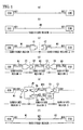
- Fig. 1(a) is a schematic view of a circuit line connecting electrical components described in auxiliary device-based wiring information
- Figs. 1(b) to 1(f) are schematic views of connections of electrical wires connecting electrical components described in region-based connector/wiring information
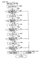
- Fig. 2 shows a flowchart of a process to be executed by the wire harness continuity inspection device according to the embodiment of the present invention.
- the auxiliary device-based wiring information includes circuit line connection information showing which electrical component and which terminals of the electrical component, the starting point and the terminating point of each of the electrical wires of these signal line, power line, and ground line are connected to, and which electrical wires, the signal line is connected to.
- Fig. 1(a) shows two ECUs which are electrical components, and a terminal "A01" of one of the ECUs is connected to a terminal "B01" of the other ECU via a circuit line.
- the wire harness continuity inspection device refers to the auxiliary device-based wiring information to specify a first terminal ("A01") of a first electrical component (ECU) and a second terminal ("B01") of a second electrical component (ECU) connected by the circuit line, described in the auxiliary device-based wiring information (referring step: S201).
- the region-based connector/wiring information describes wire harnesses arrangeable in each subdivided region of a target vehicle while including the electrical wires described in the actual wiring diagram (that is, while satisfying required specifications).
- the wire harness continuity inspection device refers to the region-based connector/wiring information to specify a first electrical wire of which one end is connected to the first terminal ("A01") of the first electrical component (ECU) described in the region-based connector/wiring information based on the wire harness information described in the region-based connector/wiring information (first specifying step: S202).
- the line width of the electrical wire of which one end is connected to the first terminal ("A01") of the first electrical component (ECU) is larger than the circuit line of Fig. 1(a) .
- the circuit line and the electrical wire are distinguished from each other in Figs. 1(a) to 1(f) .
- two electrical components are often arranged over a plurality of subdivided regions. In this case, respective wire harnesses arranged in respective subdivided regions are connected so that the terminals of the two electrical components are connected.
- the wire harness continuity inspection device determines whether a terminal connected to the other end of the first electrical wire is identical to the second terminal ("B01") of the second electrical component (ECU) (first determining step: S203). As shown in Fig.
- the wire harness continuity inspection device in the first determining step, there may be a case where the terminal connected to the other end of the first electrical wire is not identical to the second terminal ("B01") of the second electrical component (ECU) (S203: N).
- the wire harness continuity inspection device refers to the region-based connector/wiring information to specify the second electrical wire of which one end is connected to the other end of the first electrical wire described in the region-based connector/wiring information based on the wire harness information described in the region-based connector/wiring information (second specifying step: S204).
- the second specifying step will be described in detail. For example, as shown in Fig.
- an auxiliary device in Fig. 1(c) , a terminal “C01” is connected to the other end of the electrical wire W1, and the terminal "C01" is accommodated in a connector C1) connected to the other end of the first electrical wire W1 is specified from the information on a wire harness arranged in the subdivided region 1, an auxiliary device (a connector C2 in Fig. 1(c) ) fitted to the connector C1 is specified from the information on a wire harness arranged in a subdivided region 2 adjacent to the subdivided region 1, and the second electrical wire W2 of which one end is connected to a terminal "C02" connected to the terminal "C01" among the terminals accommodated in the connector C2 is specified.
- the wire harness continuity inspection device determines whether a terminal connected to the other end of the second electrical wire is identical to the second terminal ("B01") of the second electrical component (ECU) (second determining step: S205). As shown in Fig.
- the wire harness continuity inspection device in the second determining step, there may be a case where the terminal connected to the other end of the second electrical wire is not identical to the second terminal ("B01") of the second electrical component (ECU).
- the wire harness continuity inspection device refers to the region-based connector/wiring information to specify a third electrical wire of which one end is connected to the other end of the second electrical wire described in the region-based connector/wiring information based on the wire harness information described in the region-based connector/wiring information (third specifying step: S204).
- the third specifying step will be described in detail. For example, as shown in Fig. 1(d) , an auxiliary device (in Fig.
- a terminal "C03" is connected to the other end of the electrical wire W2, and the terminal "C03" is accommodated in a connector C3) connected to the other end of the second electrical wire W2 is specified from the information on a wire harness arranged in the subdivided region 2, an auxiliary device (a connector C4 in Fig. 1(d) ) fitted to the connector C3 is specified from the information on a wire harness arranged in a subdivided region 3 adjacent to the subdivided region 2, and a third electrical wire W3 of which one end is connected to the terminal "C04" connected to the terminal "C03" among the terminals accommodated in the connector C4 is specified.
- the wire harness continuity inspection device determines whether a terminal connected to the other end of the third electrical wire is identical to the second terminal ("B01") of the second electrical component (ECU) (third determining step: S205). As shown in Fig.
- the third determining step (S205) when the terminal connected to the other end of the third electrical wire is not identical to the second terminal ("B01") of the second electrical component (ECU), if the wire harness information described in the region-based connector/wiring information includes information on the fourth, fifth, ..., and n-th electrical wires W4, W5, ..., and Wn, the fourth, fifth, ..., and n-th specifying steps (S204) and the fourth, fifth, ..., and n-th determining steps (S205) are sequentially performed while raising n (S209) (where n is an integer of 2 or more).
- FIGs. 1(a) to 1(d) an overview of a case where connectors of respective wire harnesses arranged in respective subdivided regions are connected to form electrical wires connected over a plurality of subdivided regions, and the terminals of two electrical components are connected by the electrical wires has been mainly described.
- electrical wires are connected via a JB or a JC (see Fig. 1(e) ).
- a plurality of electrical wires is connected in a single subdivided region (see Fig. 1(f) ).
- the first specifying step (S202) and the first determining step (S203) are the same as those of the case where the electrical wires are connected over a plurality of subdivided regions by a connector, and description thereof will not be provided.
- the reasoning of the case where the electrical wires are connected via a JC is the same as that of the case where the electrical wires are connected via a JB, and description thereof will not be provided.
- the wire harness continuity inspection device refers to the region-based connector/wiring information to specify the second electrical wire of which one end is connected to the other end of the first electrical wire described in the region-based connector/wiring information based on the wire harness information described in the region-based connector/wiring information (second specifying step: S204).
- the second specifying step will be described in detail. As shown in Fig.
- an auxiliary device in Fig. 1(e) , a terminal "#01" is connected to the other end of the electrical wire W1, and the terminal "#01" is accommodated in a connector Ca) connected to the other end of the first electrical wire W1 is specified from the information on a wire harness arranged in the subdivided region 1, and a JB having a connector fitting position A fitted to the connector Ca is specified from a correspondence table (details of the correspondence table will be described in "Details of JB Inspection").
- connector fitting positions B and D connected to the connector fitting position A via an electrical wire or a bus bar in the JB are specified, and second electrical wires W21 and W22 of which one set of ends are connected to terminals "%01" and "#03" accommodated in respective connectors Cb and Cd to which the respective connector fitting positions B and D are fitted are specified.
- the wire harness continuity inspection device determines whether a terminal connected to the other end of the second electrical wire is identical to the second terminal ("B01") of the second electrical component (ECU) (second determining step: S205). As shown in Fig.
- the first specifying step (S202) and the first determining step (S203) are the same as those of the case where the electrical wires are connected over a plurality of subdivided regions by a connector, and description thereof will not be provided.
- the wire harness continuity inspection device refers to the region-based connector/wiring information to specify the second electrical wire of which one end is connected to the other end of the first electrical wire described in the region-based connector/wiring information based on the wire harness information described in the region-based connector/wiring information (second specifying step: S204).
- the second specifying step will be described in detail. For example, as shown in Fig.
- a connection point (in Fig. 1(f) , the other end of the electrical wire W1 is connected to one end of another electrical wire, for example, by welding or butt-joining, and "%E1" is assigned as a number identifying the welding or butt-joining point) connected to the other end of the first electrical wire W1 is specified from the information on a wire harness arranged in the subdivided region 1, and the second electrical wire W2 of which one end is connected to the connection point "%E1" is specified.
- the wire harness continuity inspection device determines whether the terminal connected to the other end of the second electrical wire is identical to the second terminal ("B01") of the second electrical component (ECU) (second determining step: S205). As shown in Fig.
- the wire harness continuity inspection device refers to the auxiliary device-based wiring information to specify the starting point and the terminating point of the circuit line and recursively analyzes whether the other end of the first electrical wire of which one end is connected to the starting point of the circuit line specified by referring to the region-based connector/wiring information or the other end of the n-th electrical wire (where n is an integer of 2 or more) of which one end is connected to the other end of the (n-1)th electrical wire is identical to the terminating point of the circuit line, or the n-th electrical wire Wn is not present, so that the (n-1)th electrical wire W(n-1) is not identical to the terminating point of the circuit line.
- the process of specifying the electrical wires of the first electrical wire W1, the second electrical wire W2, ..., and the N-th electrical wire WN and the process of determining whether the other end of each of these electrical wires is identical to the terminating point of the circuit line will be collectively referred to as "multilayer inspection.”
- the process of specifying the first electrical wire W1 of which one end is connected to the starting point of the circuit line (first specifying step: S202) and determining whether the other end of the electrical wire W1 is identical to the terminating point of the circuit line (first determining step: S203) will be referred to as "single-layer inspection.”
- Figs. 1(b) is a case where it is determined by single-layer inspection that the other end of the first electrical wire W1 is identical to the terminating point of the circuit line
- Figs. 1(c), 1(e), and 1(f) are a case where it is determined by 2-layer inspection that the other end of the second electrical wire W2 (the second electrical wire W22 in the case of Fig. 1(e) ) is identical to the terminating point of the circuit line
- Fig. 1(d) is a case where it is determined by 3-layer inspection that the other end of the third electrical wire W3 is identical to the terminating point of the circuit line.
- the wire harness continuity inspection device is configured to include an input unit 311, a database unit 312, a program storage unit 313, a data storage unit 314, a display unit 315, and a processing unit 316.
- the input unit 311 is realized as various input interfaces such as a keyboard, a mouse, and a number pad.
- the database unit 312 and the program storage unit 313 are realized as a hard disk drive (HDD), the data storage unit 314 is realized as a RAM (Random Access Memory), the display unit 315 is realized as various output devices such as a CRT display or a liquid crystal display, and the processing unit 316 is realized as a CPU (Central Processing Unit).
- the data of the auxiliary device-based wiring information, the data of the region-based connector/wiring information (if necessary, the data of the actual wiring diagram prepared based on the auxiliary device-based wiring information), and the data of the auxiliary device specification table are stored in the database unit 312.
- programs for allowing the processing unit 316 to execute the multilayer inspection and "Output of Multilayer Inspection" described later are recorded in the program storage unit 313.
- data input and output to and from the processing unit 316 executing the multilayer inspection are recorded in the data storage unit 314.
- a person who instructs the wire harness continuity inspection device of the present invention to execute the multilayer inspection performs various operations for allowing the processing unit 316 to perform computation using the input unit 311 while viewing the display unit 315.
- the multilayer inspection is classified into single-layer inspection and n-layer inspection, and first, the details of the single-layer inspection algorithm will be described.
- auxiliary device-based wiring information and the region-based connector/wiring information When executing the single-layer inspection, first, some information is extracted from the auxiliary device-based wiring information and the region-based connector/wiring information.
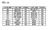
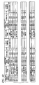
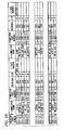
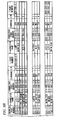
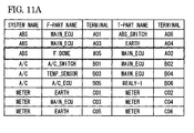
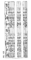
- the information extracted from the auxiliary device-based wiring information and the region-based connector/wiring information will be described with reference to an example of the auxiliary device-based wiring information and the region-based connector/wiring information, shown in Fig. 4A and 4B .
- the auxiliary device-based wiring information is made up of three elements of: system name; F-part name and terminal; and T-part name and terminal.
- the column of F-part name and the column of terminal adjacent to the column of F-part name form a pair.
- the column of T-part name and the column of terminal adjacent to the column of T-part name form a pair.
- Each row of the arrangement forming the auxiliary device-based wiring information represents the starting point and the terminating point of one circuit line described in the auxiliary device-based wiring information. For example, the first row of Fig.
- the column of system name stores information on the name of a system mounted on a vehicle
- the columns of F-part name and terminal store information on the name of an electrical component serving as a starting point (From) and the identification number of a terminal of the electrical component
- the columns of T-part name and terminal store information on the name of an electrical component serving as the terminating point (To) and the identification number of a terminal of the electrical component.
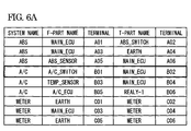
- the first to third rows of Fig. 4A represent the circuit lines in the auxiliary device-based wiring information described in the system "ABS”
- the fourth to sixth rows represent the circuit lines in the auxiliary device-based wiring information described in the system "A/C”
- the seventh to ninth rows represent the circuit lines in the auxiliary device-based wiring information described in the system "METER.”
- the auxiliary device-based wiring information made up of these elements can be prepared by extracting the information on the above-described elements from the data of the auxiliary device-based wiring information.
- the auxiliary device-based wiring information is made up of the data of a plurality of sets of auxiliary device-based wiring information for the vehicle (one set of auxiliary device-based wiring information is provided for one system).
- the prepared auxiliary device-based wiring information is stored in the data storage unit 314.
- the region-based connector/wiring information is made up of three elements of: drawing part number, F-connector name, connector part number, terminal, cavity number (hereinafter simply referred to as C/N), and F-part number; and T-connector name, connector part number, terminal, C/N, and T-part number.
- the five columns of F-connector name to F-part number form a group.
- the five columns of T-connector name to T-part number form a group.
- Each row of the arrangement forming the region-based connector/wiring information represents terminals connected to both ends of one electrical wire described in the region-based connector/wiring information. For example, the second row of Fig.
- 4B shows an electrical wire of which one end is connected to a terminal "Z03" accommodated in a C/N "9" of a connector identified by connector name "WtoW-E53” and connector part number "111-000-111” in a wire harness identified by identification number "111,” arranged in a subdivided region identified by identification number "E11,” (see the columns of F-connector name, connector part number, terminal, and C/N; information is stored in the column of F-part number when the terminal is accommodated in a JC, and the purpose thereof will be described in “Details of JC Inspection") and of which the other end is connected to a terminal "Z02" accommodated in the C/N "9” of the connector identified by connector name "WtoW-E51” and connector part number "111-000-111” (see the columns of T-connector name, connector part number, terminal, C/N; information is stored in the column of T-part number when the terminal is accommodated in the JC, and the purpose thereof will be described in "
- a portion before "-" in the drawing part number stores the identification information of a subdivided region of the vehicle
- the portion after "-" stores the identification information of the wire harness (although the information of the drawing part number is made up of two sets of information of the identification information of the subdivided region and the identification information of the wire harness, the identification information of the subdivided region and the identification information of the wire harness may be described in the region-based connector/wiring information as different information instead of using the drawing part number).
- the columns of F-connector name, connector part number, terminal, and C/N store the identification information of an auxiliary device connected to one end of the electrical wire.
- the columns of T-connector name, connector part number, terminal, and C/N store the identification information of an auxiliary device connected to the other end of the electrical wire.
- the name of the auxiliary device is stored in the F-connector name and the T-connector name.
- the name of the electrical component is stored as information. For example, the name "J/C-1" of an electrical component is stored in the F-connector name on the first row of the region-based connector/wiring information.
- Fig. 4B shows terminals connected to both ends of an electrical wire included in a wire harness identified by drawing part number "E11-111.”
- the arrangement in the middle shows terminals connected to both ends of an electrical wire included in a wire harness identified by drawing part number "E12-111.”
- the arrangement at the bottom shows terminals connected to both ends of an electrical wire included in a wire harness identified by drawing part number "E41-111.”
- the region-based connector/wiring information made up of these elements can be prepared by extracting information on the above-described elements from the data of the region-based connector/wiring information.
- the prepared region-based connector/wiring information is stored in the data storage unit 314.
- the single-layer inspection includes the process of specifying the first electrical wire W1 of which one end is connected to the starting point of a circuit line (first specifying step: S202) and determining whether the other end of the electrical wire W1 is identical to the terminating point of the circuit line (first determining step: S203).
- first specifying step: S202 the process of specifying the first electrical wire W1 of which one end is connected to the starting point of a circuit line
- second determining step: S203 first determining step: S203.
- the auxiliary device-based wiring information and the region-based connector/wiring information described in "Auxiliary Device-based Wiring Information and Region-based Connector/Wiring Information" are used.
- one optional row constituting the arrangement of the auxiliary device-based wiring information is extracted by referring to the auxiliary device-based wiring information.
- the validity determining step for the corresponding row ends, the validity determining step for another row is performed until the validity determining step is performed for all of the rows.
- the information on F-part name and terminal thereof and the information on T-part name and terminal thereof are referred to within one row extracted from the arrangement of the auxiliary device-based wiring information.
- the F-part name is "MAIN_ECU,” and the terminal thereof is "A01.”
- the T-part name is "ABS_SWITCH,” and the terminal thereof is "A02.”
- the terminal paired with the F-part name will be referred to as an F-side terminal.
- the terminal paired with the T-part name will be referred to as a T-side terminal.
- the terminal identical to the F-side terminal "A01" is present, it is checked whether there is a connector name identical to the F-part name "MAIN_ECU" among the F-connector names or the T-connector names in the same group as the terminal.
- the connector name identical to the F-part name "MAIN_ECU” is not present, it is regarded that the first electrical wire is not present (S210 of Fig. 2 : N), and a determination result of continuity fail is obtained (a process "back-tracking inspection” S211 executed subsequent to this determination will be described in "Back-tracking Inspection” described later).
- the first row of the bottom arrangement of the region-based connector/wiring information includes an F-connector name identical to the F-part name "MAIN_ECU” and a terminal identical to the F-side terminal "A01" on the same group as the F-connector name.
- the notations of the names may be different.
- a name library indicating the correspondence between the names is prepared separately, and a connector name identical to the F-part name or the T-part name of the auxiliary device-based wiring information is specified from the F-connector name or the T-connector name of the region-based connector/wiring information by referring to the name library.
- the F-part name or the T-part name of the auxiliary device-based wiring information or the F-connector name or the T-connector name of the region-based connector/wiring information is replaced with the other name by referring to the name library, and then, the validity determining step is performed.
- the validity determining step is performed. The same is applied to the n-layer inspection described later and the back-tracking inspection described later.
- one row of the arrangement of the region-based connector/wiring information in which the information on the F-part name and the terminal thereof and the information on the T-part name and the terminal thereof are included in the information on the F-connector name and the terminal thereof and the information on the T-connector name and the terminal thereof is retrieved within one row extracted from the arrangement of the auxiliary device-based wiring information.
- the first row of the auxiliary device-based wiring information of Fig. 4A is identical to the first row of the region-based connector/wiring information at the bottom of Fig.
- the single-layer inspection is the process of specifying the first electrical wire W1 of which one end is connected to the starting point of the circuit line (first specifying step: S202) and determining whether the other end of the electrical wire W1 is identical to the terminating point of the circuit line (first determining step: S203).
- This process assumes that the electrical components serving as the starting point and the terminating point of the circuit line are reliably fitted to one end and the other end of the first electrical wire W1 by connectors, and that the terminal on the electrical component side is electrically connected to the one end or the other end of the first electrical wire W1.
- FIG. 16A to 16C show another example of the auxiliary device-based wiring information, the region-based connector/wiring information, and the part number correspondence table. Since the region-based connector/wiring information of Fig. 16B is the same as that of Fig. 4A , description thereof will not be provided.
- the auxiliary device-based wiring information is made up of three elements: system name; F-part name, part number, terminal, and C/N; and T-part name, part number, terminal, and C/N, shown in Fig. 16A . That is, part number and C/N corresponding to F-part name and part number and C/N corresponding to T-part name are added to the auxiliary device-based wiring information shown in Fig. 4A .
- the column of F-part name and the columns of part number, terminal, and C/N arranged to the right of the column of F-part name form a pair.
- the column of T-part name and the columns of part number, terminal, and C/N arranged to the right of the column of T-part name form a pair.
- Each row of the arrangement forming the auxiliary device-based wiring information represents the starting point and the terminating point of one circuit line described in the auxiliary device-based wiring information.
- the first row of Fig. 16A represents a circuit line of which the starting point is a terminal "A01" accommodated in a C/N "4" of an electrical component-side connector identified by a part number "K-000-111" included in an electrical component "MAIN_ECU” in the auxiliary device-based wiring information described in a system "ABS” (see the columns of F-part name, part number, terminal, and C/N), and of which the terminating point is a terminal "A02" accommodated in a C/N "4" of a part number "K-000-112" included in an electrical component "ABS_SWITCH.”
- the column of system name stores information on the name of a system mounted on a vehicle
- the columns of F-part name, part number, terminal, and C/N store information on the name of an electrical component serving as a starting point (
- the first to third rows of Fig. 16A represent the circuit lines in the auxiliary device-based wiring information described in the system "ABS”
- the fourth to sixth rows represent the circuit lines in the auxiliary device-based wiring information described in the system "A/C”
- the seventh to ninth rows represent the circuit lines in the auxiliary device-based wiring information described in the system "METER.”
- the auxiliary device-based wiring information made up of these elements can be prepared by extracting the information on the above-described elements from the data of the auxiliary device-based wiring information.
- the auxiliary device-based wiring information is made up of the data of a plurality of sets of auxiliary device-based wiring information for the vehicle (one set of auxiliary device-based wiring information is provided for one system).
- the prepared auxiliary device-based wiring information is stored in the data storage unit 314.
- the part number correspondence table is made up of a pair of two arrangements of part number and connector part number.
- the column of part number stores information on the identification number of a connector included in an electrical component
- the column of connector part number stores information on a connector part number that can be fitted to the connector specified by the part number.
- the part number correspondence table shows that the part number and the connector part number adjacent to each other are in a fitted relation.
- the first row of Fig. 16C shows that a connector on an electrical component side identified by the part number "K-000-111" and a connector specified by the connector part number "111-000-111" are in a fitted relation.
- the part number correspondence table made up of these elements can be prepared by extracting information on the above-described elements from the data of the region-based connector/wiring information.
- the prepared connector name correspondence table is stored in the data storage unit 314.
- the single-layer inspection algorithm in which the validity of the combination of the electrical components serving as the starting point and the terminating point of the circuit line and the one end and the other end of the first electrical wire W1 is added to the process described with reference to Figs. 4A and 4B will be described.
- one optional row constituting the arrangement of the auxiliary device-based wiring information is extracted by referring to the auxiliary device-based wiring information.
- the validity determining step for the corresponding row ends, the validity determining step for another row is performed until the validity determining step is performed for all of the rows.
- the information on F-part name, part number thereof, terminal thereof, and C/N thereof, and the information on T-part name, part number thereof, terminal thereof, and C/N thereof are referred to within one row extracted from the arrangement of the auxiliary device-based wiring information. As shown in Fig.
- the F-part name is "MAIN_ECU," the part number thereof is “K-000-111,” the terminal thereof is “A01,” and the C/N thereof is “4.”
- the T-part name is "ABS_SWITCH,” the part number thereof is “K-000-111,” the terminal thereof is “A02,” and the C/N thereof is “4.”
- the part number, the terminal, and the C/N paired with the F-part name will be referred to as an F-side part number, an F-side terminal, and an F-side C/N.
- the part number, the terminal, and the C/N paired with the T-part name will be referred to as a T-side part number, a T-side terminal, and a T-side C/N.
- the electrical component itself identified by the F-part name "MAIN_ECU" described in the auxiliary device-based wiring information is not described in the region-based connector/wiring information. It can be understood from Fig. 16B that in the bottom arrangement of the region-based connector/wiring information, the first row includes the F-connector name identical to the F-part name "MAIN_ECU,” includes the connector part number identical to the connector part number "111-000-111,” and includes the terminal identical to the F-side terminal "A01" and the F-side C/N "4.”
- the notations of the names may be different.
- a name library indicating the correspondence between the names is prepared separately, and a connector name identical to the F-part name or the T-part name of the auxiliary device-based wiring information is specified from the F-connector name or the T-connector name of the region-based connector/wiring information by referring to the name library.
- the F-part name or the T-part name of the auxiliary device-based wiring information or the F-connector name or the T-connector name of the region-based connector/wiring information is replaced with the other name by referring to the name library, and then, the validity determining step is performed.
- the validity determining step is performed. The same is applied to the n-layer inspection described later and the back-tracking inspection described later.
- connection means includes (1) connector-based connection (see Fig. 1(c) ), (2) JB-based connection (see Fig.
- connection means (1) will be referred to as "WtoW inspection”
- the electrical wire specifying method corresponding to the connection means (2) will be referred to as “JB inspection”
- the electrical wire specifying method corresponding to the connection means (3) will be referred to as “JC inspection”
- the electrical wire specifying method corresponding to the connection means (4) will be referred to as “W/S (Weld Splice) inspection” and "B/S (Butt Splice) inspection.”
- the 2-layer inspection performs these "WtoW inspection,” “JB inspection,” “JC inspection,” “W/S inspection,” and “B/S inspection”
- connection means for connecting the other end of the first electrical wire W1 and one end of the second electrical wire W2 is any one of the specifying methods (1) to (4) corresponding to the specifying method (the key point is that since it is not possible to understand connection means for connecting the other end of the first electrical wire W1 and one end of the second electrical wire W2 is any one of the specifying methods (1) to (4) corresponding to the specifying method (
- the electrical wire specifying method is used sequentially in the order of WtoW inspection, JB inspection, JC inspection, W/S inspection, and B/S inspection.
- the order of using the electrical wire specifying method in the present invention is not limited to the order of WtoW inspection, JB inspection, JC inspection, W/S inspection, and B/S inspection.
- the electrical wire specifying method may be used in descending order of frequencies in which they are used as the electrical wire connection means. As a result, it is possible to specify the second electrical wire W2 with a smaller amount of computation.
- the details of the electrical wire specifying method will be described in the order of WtoW inspection, JB inspection, JC inspection, W/S inspection, and B/S inspection.
- auxiliary device-based wiring information the region-based connector/wiring information, the connector name correspondence table, and the connector part number correspondence table shown in Figs. 5A to 5D .
- the auxiliary device-based wiring information and the region-based connector/wiring information are the same as those described in "Auxiliary Device-Based Wiring Information And Region-Based Connector/Wiring Information" in "Details of Single-Layer Inspection," and description thereof will not be provided.
- the connector name correspondence table is made up of two arrangements of region name and connector name.
- the column of region name stores information on the identification number of a subdivided region where a wire harness is arranged, and the column of connector name stores information on the identification information of an auxiliary device connected to one end of an electrical wire included in the wire harness.
- the connector name correspondence table shows that one set of region name and connector name and the other set of region name and connector name adjacent thereto are in such a relation that auxiliary devices specified by the connector names are fitted to each other. For example, the first row of Fig.
- 5C shows that an auxiliary device specified by the connector name "WtoW-E12," of a wire harness arranged in the subdivided region identified by the identification number "E11" and an auxiliary device specified by the connector name "WtoW-E11-1,” of a wire harness arranged in the subdivided region identified by the identification number "E12" are in a fitted relation.
- the connector name correspondence table made up of these elements can be prepared by extracting information on the above-described elements from the data of the region-based connector/wiring information.
- the prepared connector name correspondence table is stored in the data storage unit 314.
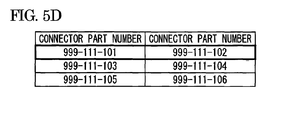
- the connector part number correspondence table is made up a pair of arrangements of two connector part numbers as shown in Fig. 5D .
- the connector part number stores information on the identification information of an auxiliary device.
- the connector part number correspondence table shows that one connector part number and the other connector part number adjacent thereto are in such a relation that auxiliary devices specified by the connector part numbers are fitted to each other.
- the first row of Fig. 5D shows that an auxiliary device specified by the connector part number "999-111-101" and an auxiliary device specified by the connector part number "999-111-102" are in a fitted relation.
- the connector part number correspondence table made up of these elements can be prepared by extracting information on the above-described elements from the data of the region-based connector/wiring information.
- the prepared connector part number correspondence table is stored in the data storage unit 314.
- the checking is subsequently performed with respect to the region-based connector/wiring information by referring to the information on the rows specified from the connector name correspondence table and the connector part number correspondence table.
- a row in which the identification information of a subdivided region in the drawing part number is identical to a counterpart region name "E11" of the row specified from the connector name correspondence table is extracted.
- a connector of which the F-connector name or the T-connector name is identical to the counterpart connector name "WtoW-E41-2" of the row specified from the connector name correspondence table is extracted within the extracted row.
- a connector of which the connector part number in the same group as the F-connector name or the connector part number in the same group of the T-connector name is identical to the counterpart connector part number "999-111-101" of the row specified from the connector part number correspondence table is extracted. It can be understood from Fig. 5B that these sets of information are included in the connector part number in the same group as the drawing part number, the F-connector name, and the F-connector name on the third row at the top of the region-based connector/wiring information. Furthermore, it is checked whether the C/Ns of the fitting connectors are identical. One row of the region-based connector/wiring information specified in this way (the third row at the top of the region-based connector/wiring information in Fig.
- connection means for connecting the first electrical wire W1 and the second electrical wire W2 is not the connector-based connection (1), and the inspection transitions to JB inspection.
- the T-connector name is identical to the T-part name "ABS_SWITCH.”
- the other end of the second electrical wire W2 is identical to the terminating point of the circuit line in the row described in the auxiliary device-based wiring information (S205 of Fig. 2 : Y, hereinafter a process corresponding to a determination result of "Yes” will be referred to as "Y").
- a process corresponding to a determination result of "Yes" will be referred to as "Y").
- the fitting state due to connectors between the electrical component serving as the terminating point of the circuit line and the other end of the second electrical wire W2 may be checked, so that the accuracy of the continuity inspection may be improved further.
- the circuit line in the row described in the auxiliary device-based wiring information is electrically connected in the region-based connector/wiring information (S207 of Fig. 2 ), and the validity determining step ends.
- one row of the arrangement of the region-based connector/wiring information in which the information on the T-part name and the terminal thereof is included in the information on the F-connector name and the terminal thereof or the information on the T-connector name and the terminal thereof is retrieved within one row extracted from the arrangement of the auxiliary device-based wiring information.
- the first row of the auxiliary device-based wiring information of Fig. 5A is identical to the third row at the top of the region-based connector/wiring information of Fig.
- the starting point and the terminating point of the circuit line represented by one row extracted from the arrangement of the auxiliary device-based wiring information are electrically connected by the electrical wires connected by the connector, represented by the corresponding two rows (two rows in the case of 2-layer inspection, and n rows in the case of n-layer inspection) of the region-based connector/wiring information (continuity success).
- the inspection transitions to the JB inspection or the 3-layer inspection in the course of the WtoW inspection.
- the JB inspection is executed when it is not possible to specify the electrical wire in the WtoW inspection.
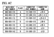
- the details of the JB inspection will be described with reference to examples of the auxiliary device-based wiring information, the region-based connector/wiring information, the JB-connector correspondence table, and the JB terminal connection correspondence table, shown in Figs. 6A to 6D .
- the auxiliary device-based wiring information and the region-based connector/wiring information are the same as those described in "Auxiliary Device-Based Wiring Information And Region-Based Connector/Wiring Information" in "Details of Single-Layer Inspection," and description thereof will not be provided.
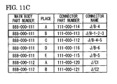
- the JB-connector correspondence table is made up of main body part number, place, connector part number, and connector name.
- the column of main body part number stores information on the identification information for identifying a JB
- the column of place also referred to as a connector fitting position
- the column of connector part number stores information on the identification number of a connector that can be inserted into the connector fitting position
- the column of connector name stores information on the name of a connector that can be inserted into the connector fitting position.
- these four sets of information form a group.
- the JB-connector correspondence table shows that a connector specified by connector part number and connector name can be inserted into the designated connector fitting position of the JB identified by main body part number.
- the first row of Fig. 6C shows that a connector identified by the connector part number "111-000-114" and the connector name of "J/B-4" can be inserted into the connector fitting position "A" of the JB identified by the identification number "888-000-111.”
- the JB-connector correspondence table made up of these elements can be prepared by extracting information on the above-described elements from the data of the region-based connector/wiring information.
- the prepared JB-connector correspondence table is stored in the data storage unit 314.
- the JB terminal connection correspondence table is made up of main body part number and cavity connection.
- the column of main body part number stores the identification information for identifying a JB
- the column of cavity connection stores information on a connection state between terminals within the JB.
- these two sets of information form a group.
- the JB terminal connection correspondence table shows that terminals at least at two designated cavity positions of a JB identified by main body part number are electrically connected. For example, the eighth row of Fig.
- FIG. 6D shows that in the JB identified by the identification number "888-000-111," the cavity position "33" at the connector fitting position “A” (see “A33” of cavity connection), the cavity position "23” at the connector fitting position “B” (see “B23” of cavity connection), and the cavity position "32” at the connector fitting position “D” (see “D32” of cavity connection) are electrically connected within the JB (in Fig. 6D , "&” indicates that cavities are electrically connected, and “+” indicates that a cavity and an electrical element (a relay, a fuse, or the like) are electrically connected).
- the JB terminal connection correspondence table made up of these elements can be prepared by extracting information on the above-described elements from the data of the region-based connector/wiring information.
- the prepared JB terminal connection correspondence table is stored in the data storage unit 314.
- the eighth row of the JB terminal connection correspondence table (as for the connector fitting position "A” and the C/N "33,” refer to "A33" within the cavity connection "A33&B23&D32"). If a desired row is present in the JB terminal connection correspondence table, it is possible to specify to which terminal and at which cavity position of the JB, the other end of the first electrical wire W1 is electrically connected. For example, the eighth row of the JB terminal connection correspondence table of Fig.
- the second electrical wire W21 of which one end is connected to the cavity position "23" of the connector fitting position "B” and the second electrical wire W22 of which one end is connected to the cavity position "32" of the connector fitting position “D" are candidates for the second electrical wire W2 (see Fig. 1(e) ).
- the region-based connector/wiring information is checked.
- the connector part number and the connector name of one row specified from the JB-connector correspondence table it is checked whether a row in which the connector part number is identical to the F-connector name and the connector part numbers in the same group of the F-connector name or the T-connector name and the connector part numbers in the same group as the T-connector name is not present in the region-based connector/wiring information.
- the corresponding row When the corresponding row is present, it is checked whether a row including the identical C/N is not present in the region-based connector/wiring information by referring to the cavity position of the connector fitting position specified from the JB terminal connection correspondence table. It can be understood from Fig. 6B that the F-connector name, the connector part number, and the C/N identical to the connector part number "111-000-113," the connector name "J/B-1-2-3,” and the cavity position "23" on the second row of the JB-connector correspondence table are included in the third row at the bottom of the region-based connector/wiring information.
- the F-connector name, the connector part number, and the C/N identical to the connector part number "111-000-116," the connector name "J/B-6," and the cavity position "32" on the fourth row of the JB-connector correspondence table are included in the fifth row at the bottom of the region-based connector/wiring information.
- One set of rows (the third and fifth rows at the bottom of the region-based connector/wiring information in Fig. 6B ) of the region-based connector/wiring information specified in this way become the candidates for the second electrical wire W2 of which one end is connected to the other end of the first electrical wire W1.
- the connection means for connecting the first electrical wire W1 and the second electrical wire W2 is not the JB-based connection (2), and the inspection transitions to JC inspection.
- the T-connector name is identical to the T-part name "MAIN_ECU.”
- the other end of the second electrical wire W2 is identical to the terminating point of the circuit line in the row described in the auxiliary device-based wiring information (S205 of Fig. 2 : Y).
- the fitting state due to connectors between the electrical component serving as the terminating point of the circuit line and the other end of the second electrical wire W2 may be checked, so that the accuracy of the continuity inspection may be improved further.
- the circuit line in the row described in the auxiliary device-based wiring information is electrically connected in the region-based connector/wiring information (S207 of Fig. 2 ), and the validity determining step ends.
- the terminal is not identical to the T-side terminal "B02," and it is not possible to specify the next electrical wire.
- the fifth row at the bottom of the region-based connector/wiring information is regarded as the second electrical wire W2
- the T-side terminal "B02" is checked with respect to the fifth row at the bottom of the region-based connector/wiring information.
- connection means for connecting the first electrical wire W1 and the second electrical wire W2 is not the JB-based connection (2), and the inspection transitions to JC inspection.
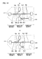
- Figs. 17(a) and 17(b) are diagrams for explaining back-tracking to the branches of multilayer inspection to be executed by the wire harness continuity inspection device according to the embodiment of the present invention.
- arrows show that n-layer inspection of the multilayer inspection is executed.
- the number “2" before “-” among the numbers “1,” “2-1,” “2-2,” or “2-3” positioned above the arrows and the number “3” before “-” among the numbers “3-1,” “3-2,” or “3-3” represent the layer n of the multilayer inspection being executed, and the numbers “1,” “2,” and “3” after “-” represent the information for identifying the multilayer inspection performed for each of the branched electrical wires.
- 2-3 multilayer inspection is performed for the branched electrical wire W23.
- the 3-layer inspection and the subsequent inspection are performed by sequentially regarding the electrical wires W22 and W23 as the second electrical wire W2.
- the 4-layer inspection and the subsequent inspection are performed by sequentially regarding the electrical wires W32 and W33 as the third electrical wire W3.
- the single-layer inspection is not executed repeatedly, and the process associated with the multilayer inspection is simplified.
- one row of the arrangement of the region-based connector/wiring information in which the information on the T-part name and the terminal thereof is included in the information on the F-connector name and the terminal thereof and the information on the T-connector name and the terminal thereof is retrieved within one row extracted from the arrangement of the auxiliary device-based wiring information.
- the fourth row of the auxiliary device-based wiring information of Fig. 6A is identical to the fifth row of the region-based connector/wiring information at the bottom of Fig.
- the starting point and the terminating point of the circuit line represented by one row extracted from the arrangement of the auxiliary device-based wiring information are electrically connected by electrical wires connected by the JB represented by the corresponding two rows (two rows in the case of 2-layer inspection, and n rows in the case of n-layer inspection) of the region-based connector/wiring information (continuity success).
- the inspection transitions to the 3-layer inspection in the course of the JB inspection or to the JC inspection after the end of the JB inspection.
- the JC inspection is executed when it is not possible to specify the electrical wire in the JB inspection.
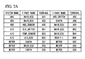
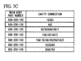
- the details of the JC inspection will be described with reference to examples of the auxiliary device-based wiring information, the region-based connector/wiring information, and the JC terminal connection correspondence table, shown in Figs. 7A to 7C .
- the auxiliary device-based wiring information and the region-based connector/wiring information are the same as those described in "Auxiliary Device-Based Wiring Information And Region-Based Connector/Wiring Information" in "Details of Single-Layer Inspection," and description thereof will not be provided.
- the JC terminal connection correspondence table is made up of main body part number and cavity connection.
- the column of main body part number stores the identification information for identifying a JC
- the column of cavity connection stores information on a connection state between terminals within the JC.
- these two sets of information form a group.
- the JB terminal connection correspondence table shows that terminals at least at two designated cavity positions of a JC identified by main body part number are electrically connected. For example, the first row of Fig.
- the JC terminal connection correspondence table made up of these elements can be prepared by extracting information on the above-described elements from the data of the region-based connector/wiring information.
- the prepared JC terminal connection correspondence table is stored in the data storage unit 314.
- the T-part name within the information on the other end of the first electrical wire W1 is referred to.
- the column of T-part name when a terminal in the same group as the T-part name is accommodated in the JC, the information on the identification number for identifying the JC is stored.
- the inspection transitions to "W/S inspection.” It can be understood from Fig. 7B that "800-200-100" is stored in the T-part name.
- the second row of the JC terminal connection correspondence table of Fig. 7C shows that the cavity "4" of the JC identified by the main body part number "800-200-100" is electrically connected to the cavity "5" of the JC. Since the C/N is "4" within the information on the other end of the first electrical wire W1, the cavity connected to the other end of the first electrical wire W1 has a number other than "4.”
- the region-based connector/wiring information is checked. First, it is checked whether a row in which the F-part name or the T-part name is identical to the main body part number of the corresponding row of the JC terminal connection correspondence table is not present in the region-based connector/wiring information. When the corresponding row is present, it is checked whether a row including the identical C/N is not present in the region-based connector/wiring information by referring to the cavity connection of the corresponding row of the JC terminal connection correspondence table. When the corresponding row is present, it is checked whether the T-connector names and the connector part numbers are identical to each other. It can be understood from Fig.
- the C/N identical to the cavity connection "5" is included in the second row at the bottom of the region-based connector/wiring information.
- the T-connector name and the connector part number of the first and second rows at the bottom of the region-based connector/wiring information are identical to "J/C-4" and "999-111-102.”
- the second row (the second row at the bottom of the region-based connector/wiring information in Fig. 7B ) of the region-based connector/wiring information specified in this way becomes the second electrical wire W2 of which one end is connected to the other end of the first electrical wire W1.
- the connection means for connecting the first electrical wire W1 and the second electrical wire W2 is not the JC-based connection (2), and the inspection transitions to W/S inspection.
- the T-connector name is identical to the T-part name "METER.”
- the other end of the second electrical wire W2 is identical to the terminating point of the circuit line in the row described in the auxiliary device-based wiring information (S205 of Fig. 2 : Y).
- the fitting state due to connectors between the electrical component serving as the terminating point of the circuit line and the other end of the second electrical wire W2 may be checked, so that the accuracy of the continuity inspection may be improved further.
- the circuit line in the row described in the auxiliary device-based wiring information is electrically connected in the region-based connector/wiring information (S207 of Fig. 2 ), and the validity determining step ends.
- connection means for connecting the first electrical wire W1 and the second electrical wire W2 is not the JC-based connection (3), and the inspection transitions to "W/S inspection.”
- one row of the arrangement of the region-based connector/wiring information in which the information on the T-part name and the terminal thereof is included in the information on the F-connector name and the terminal thereof and the information on the T-connector name and the terminal thereof is retrieved within one row extracted from the arrangement of the auxiliary device-based wiring information.
- the eighth row of the auxiliary device-based wiring information of Fig. 7A is identical to the second row at the bottom of the region-based connector/wiring information of Fig.
- the starting point and the terminating point of the circuit line represented by one row extracted from the arrangement of the auxiliary device-based wiring information are electrically connected by electrical wires connected by the JC represented by the corresponding two rows (two rows in the case of 2-layer inspection, and n rows in the case of n-layer inspection) of the region-based connector/wiring information (continuity success).
- the inspection transitions to the 3-layer inspection in the course of the JC inspection or to the W/S inspection after the end of the JC inspection.
- the W/S inspection is executed when it is not possible to specify the electrical wire in the JC inspection.
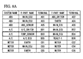
- the details of the W/S inspection will be described with reference to examples of the auxiliary device-based wiring information and the region-based connector/wiring information, shown in Figs. 8A and 8B .
- the auxiliary device-based wiring information and the region-based connector/wiring information are the same as those described in "Auxiliary Device-Based Wiring Information And Region-Based Connector/Wiring Information" in "Details of Single-Layer Inspection," and description thereof will not be provided.
- the information on the other end of the (n-1)th electrical wire W(n-1) recorded in the data storage unit 314 is referred to.
- information unique to the W/S-based connection is included in the information on the other end of the (n-1)th electrical wire W(n-1). That is, unique character strings of "W/S-1,” “SSS-000-000,” and "%1" are described in the T-connector name, the connector part number, and the terminal, respectively.
- the connector part number and the C/N in the same group as the T-connector name are referred to within the information on the other end of the first electrical wire W1.
- "SSS-000-000” and "1" are stored in the T-connector part number and the C/N as information.
- the inspection transitions to "B/S inspection.” It can be understood from Fig. 8B that in the fourth row at the top of the region-based connector/wiring information, "SSS-000-000” and "1" are stored in the T-connector part number and the C/N, respectively.
- the corresponding data are stored in the T-connector name and the C/N described above, by referring to the identification information "E11" of a subdivided region in the drawing part number "E11-111" within the information on the first electrical wire W1, it is checked whether a row in which the connector part number and the C/N are "SSS-000-000” and "1" is not present in the rows of the region-based connector/wiring information including the identification information "111" in the drawing part number. When the corresponding row is present, it is checked whether the F-connector name and the terminal of the row are identical to the T-connector name and the terminal within the information on the first electrical wire W1.
- the T-connector name is identical to the T-part name "MAIN_ECU.”
- the other end of the second electrical wire W2 is identical to the terminating point of the circuit line in the row described in the auxiliary device-based wiring information (S205 of Fig. 2 : Y).
- the fitting state due to connectors between the electrical component serving as the terminating point of the circuit line and the other end of the second electrical wire W2 may be checked, so that the accuracy of the continuity inspection may be improved further.
- the circuit line in the row described in the auxiliary device-based wiring information is electrically connected in the region-based connector/wiring information (S207 of Fig. 2 ), and the validity determining step ends.
- connection means for connecting the first electrical wire W1 and the second electrical wire W2 is not the welding (W/S)-based connection (4), and the inspection transitions to "B/S inspection.”
- one row of the arrangement of the region-based connector/wiring information in which the information on the T-part name and the terminal thereof is included in the information on the F-connector name and the terminal thereof and the information on the T-connector name and the terminal thereof is retrieved within one row extracted from the arrangement of the auxiliary device-based wiring information.
- the fifth row of the auxiliary device-based wiring information of Fig. 8A is identical to the second row at the top of the region-based connector/wiring information of Fig.
- the starting point and the terminating point of the circuit line represented by one row extracted from the arrangement of the auxiliary device-based wiring information are electrically connected by electrical wires connected by the W/S represented by the corresponding two rows (two rows in the case of 2-layer inspection, and n rows in the case of n-layer inspection) of the region-based connector/wiring information (continuity success).
- the inspection transitions to the 3-layer inspection in the course of the W/S inspection or to the B/S inspection after the end of the W/S inspection.
- the B/S inspection is executed when it is not possible to specify the electrical wire in the W/S inspection.
- the details of the B/S inspection will be described with reference to examples of the auxiliary device-based wiring information and the region-based connector/wiring information, shown in Figs. 9A and 9B .
- the auxiliary device-based wiring information and the region-based connector/wiring information are the same as those described in "Auxiliary Device-Based Wiring Information And Region-Based Connector/Wiring Information" in "Details of Single-Layer Inspection," and description thereof will not be provided.
- the information on the other end of the (n-1)th electrical wire W(n-1) recorded in the data storage unit 314 is referred to.
- information unique to the B/S-based connection is included in the information on the other end of the (n-1)th electrical wire W(n-1). That is, no information (NULL) is stored in the T-connector name, the connector part number, and the C/N, and unique information of "#A1" is described in the terminal.
- the T-connector name, the connector part number in the same group as the T-connector name, and the C/N in the same group as the T-connector name are referred to within the information on the other end of the first electrical wire W1.
- no information NULL
- the T-connector name, the connector part number, and the C/N no information (NULL) is stored in the T-connector name, the connector part number, and the C/N.
- the F-connector name is identical to the T-part name "MAIN_ECU.”
- the other end of the second electrical wire W2 is identical to the terminating point of the circuit line in the row described in the auxiliary device-based wiring information (S205 of Fig. 2 : Y).
- the fitting state due to connectors between the electrical component serving as the terminating point of the circuit line and the other end of the second electrical wire W2 may be checked, so that the accuracy of the continuity inspection may be improved further.
- the circuit line in the row described in the auxiliary device-based wiring information is electrically connected in the region-based connector/wiring information (S207 of Fig. 2 ), and the validity determining step ends.
- connection means for connecting the first electrical wire W1 and the second electrical wire W2 is not the butt-joining-based connection (4), and B/S inspection ends.
- one row of the arrangement of the region-based connector/wiring information in which the information on the T-part name and the terminal thereof is included in the information on the F-connector name and the terminal thereof and the information on the T-connector name and the terminal thereof is retrieved within one row extracted from the arrangement of the auxiliary device-based wiring information.
- the third row of the auxiliary device-based wiring information of Fig. 9A is identical to the fifth row at the top of the region-based connector/wiring information of Fig.
- the starting point and the terminating point of the circuit line represented by one row extracted from the arrangement of the auxiliary device-based wiring information are electrically connected by electrical wires connected by the B/S represented by the corresponding two rows (two rows in the case of 2-layer inspection, and n rows in the case of n-layer inspection) of the region-based connector/wiring information (continuity success).
- the B/S inspection ends in the course of the B/S inspection or the B/S inspection ends after the flow reaches the end of the B/S inspection.
- the fact that the B/S inspection ends without reaching continuity success means that it is not possible to specify the second electrical wire W2 by any of "WtoW inspection,” “JB inspection,” “JC inspection,” “W/S inspection,” and “B/S inspection.”
- continuity fail S208
- the validity determining step is executed for the circuit line of another row of the auxiliary device-based wiring information.
- One row of the auxiliary device-based wiring information determined as continuity fail in this way is recorded in the data storage unit 314, and a list of circuit lines of the auxiliary device-based wiring information determined as continuity fail is displayed on the display unit 315.
- the electrical wire is regarded as the n-th electrical wire Wn (S1012), and the flow proceeds to the process of S206.
- the JB inspection is performed (S1003).
- the electrical wire is regarded as the n-th electrical wire Wn (S1012), and the flow proceeds to the process of S206.
- the JC inspection is performed (S1005).
- the electrical wire is regarded as the n-th electrical wire Wn (S1012), and the flow proceeds to the process of S206.
- the W/S inspection is performed (S1007).
- the electrical wire is regarded as the n-th electrical wire Wn (S1012), and the flow proceeds to the process of S206.
- the B/S inspection is performed (S1009).
- the electrical wire is regarded as the n-th electrical wire Wn (S1012), and the flow proceeds to the process of S206.
- it is not possible to specify the electrical wire connected by the B/S by the B/S inspection (S1010: N) it is regarded that the n-th electrical wire Wn is not present (S1013), and the flow proceeds to the process of S206.
- fuses and relays are included in the auxiliary device-based wiring information, these components are described as being integrated in the JB in the region-based connector/wiring information. That is, as for the fuses and relays, the name for identifying the fuse is described in the F-part name of the auxiliary device-based wiring information, and the terminal of the fuse is described in the terminals in the same group as the F-part name. However, the name for identifying the JB is described in the F-connector name of the region-based connector/wiring information.
- the validity determining step regarding the circuit line in which a fuse or a relay is connected to the starting point thereof is performed in the single-layer inspection, it is not possible to specify the first electrical wire W1 of which one end is connected to the fuse or the relay from the region-based connector/wiring information (this is because in the region-based connector/wiring information, one end of the first electrical wire W1 is connected to the JB). Therefore, it is regarded that the circuit line described in the auxiliary device-based wiring information is not electrically connected in the region-based connector/wiring information. In order to prevent an erroneous validity determining step, the back-tracking inspection described later is performed.
- auxiliary device-based wiring information the region-based connector/wiring information, the JB-connector correspondence table, and the JB terminal connection correspondence table, shown in Figs. 11A to 11D .
- the auxiliary device-based wiring information, the region-based connector/wiring information, the JB-connector correspondence table, and the JB terminal connection correspondence table are the same as those described in "Details of JB Inspection," and description thereof will not be provided.
- the single-layer inspection Before the back-tracking inspection is executed, the single-layer inspection has been executed.
- the single-layer inspection by referring to the entire arrangement of the region-based connector/wiring information, when a terminal identical to the F-side terminal is not present among the terminals in the same group as the F-connector name or the terminals in the same group as the T-connector name, or when although a terminal identical to the F-side terminal is present, a terminal identical to the F-part name is not present among the F-connector names or the T-connector names in the same group as the terminal, the back-tracking inspection is executed.
- the F-part name of the corresponding row extracted from the auxiliary device-based wiring information is referred to. It can be understood from Fig. 11A that in the third row of the auxiliary device-based wiring information, a description "F:DOME" representing a fuse is included in the F-part name.
- the information excluding the description of fuse or relay is extracted among the main body part number and the cavity connection of the corresponding row referred to.
- the fourth row of the JB terminal connection correspondence table shows that the main body part number is "888-000-111" and the description "F:DOME" representing a fuse is electrically connected to the cavity position "4" (refer to "B4") of the connector fitting position "B.”
- a connector fitted to the connector fitting position described in the cavity connection is specified based on the information excluding the description of fuse or relay among the extracted main body part number and the extracted cavity connection. It can be understood from Fig. 11C that the main body part number "888-000-111" and the connector fitting position "B" are included in the second row of the JB-connector correspondence table. In this way, it can be understood that a connector specified by the connector part number "888-000-111" and the connector name "J/B-1-2-3" described in the second row of the JB-connector correspondence table includes a terminal electrically connected to the above-described fuse.
- the region-based connector/wiring information is checked.
- the connector part number and the connector name of one row specified from the JB-connector correspondence table it is checked whether a row in which the connector part number is identical to the F-connector name and the connector part numbers in the same group of the F-connector name or the T-connector name and the connector part numbers in the same group as the T-connector name is present in the region-based connector/wiring information. It can be understood from Fig.
- the multilayer inspection as described in "Single-Layer Inspection Algorithm," one optional row constituting the arrangement of the auxiliary device-based wiring information is extracted by referring to the auxiliary device-based wiring information, and the multilayer inspection is executed with respect to the extracted one row.
- the result of the determination by the multilayer inspection is obtained in respective rows constituting the arrangement of the auxiliary device-based wiring information.
- the simplest method of outputting the result of the multilayer inspection is to output continuity success or continuity fail in respective rows constituting the arrangement of the auxiliary device-based wiring information.
- this method can identify continuity success or continuity fail, when the result of the determination by the multilayer inspection is continuity success, it is not possible to specify the electrical wire via which one row constituting the arrangement of the auxiliary device-based wiring information is connected. Furthermore, when the result of the determination by the multilayer inspection is continuity fail, it is not possible to specify the layer of the multilayer inspection in which the continuity fail is obtained.
- a method of recording the inspection history of the multilayer inspection reaching continuity success or continuity fail and outputting and displaying the inspection history will be described with reference to the conceptual diagrams of a method of recording the result of the multilayer inspection to be executed by the wire harness continuity inspection device according to the embodiment of the present invention, shown in Figs. 12(a) to 12(g) , Figs. 13(a) to 13(f) , and Figs. 14(a) to 14(c) .
- the single-layer inspection is executed.
- the single-layer inspection first, as described in "Single-Layer Inspection Algorithm," one optional row constituting the arrangement of the auxiliary device-based wiring information is extracted by referring to the auxiliary device-based wiring information. The information described in the one row is recorded. After that, the inspection history is recorded in correlation with the one row. After the multilayer inspection for the corresponding one row ends, the multilayer inspection for another one row is executed. In this case, the inspection history is recorded in correlation with the corresponding one row.
- the multilayer inspection executes n-layer inspection.
- the inspection is executed in the order of "WtoW inspection,” “JB inspection,” “JC inspection,” “W/S inspection,” and “B/S inspection.”
- WtoW inspection of the n-layer inspection is executed, as described in “Details of WtoW Inspection”
- inspection results of continuity success, transition to JB inspection, and transition to (n+1)-layer inspection are considered.
- a status "continuity success” in "WtoW inspection” of "n-layer inspection” is recorded in correlation with the corresponding one row (in Fig. 12(b) , "O" represents the note of continuity success).
- the result of the inspection in the WtoW inspection of the n-layer inspection is continuity success, the recording of the inspection history for the corresponding one row ends there.
- an "L"-shaped line extending downward from "-" positioned to the right of "WtoW inspection” represents "transition to 3-layer inspection”).
- an "L"-shaped line extending downward from "-" positioned to the right of "JB inspection” represents "transition to 3-layer inspection”).
- an "L"-shaped line extending downward from "-" positioned to the right of "JC inspection” represents “transition to 3-layer inspection”).
- an "L"-shaped line extending downward from "-" positioned to the right of "W/S inspection” represents "transition to 3-layer inspection”).
- the flow of recording the result of the multilayer inspection has been described.
- the method of recording inspection history has been described in detail for respective inspection results of continuity success, continuity fail, transition to "WtoW inspection,” “JB inspection” “JC inspection,” “W/S inspection,” and “B/S inspection” in the 2-layer inspection, and transition to 3-layer inspection, mainly by way of the 2-layer inspection as an example of the n-layer inspection with reference to Figs. 12(a) to 14(c) .
- the inspection history of the n-layer inspection of the 3-layer inspection and the subsequent inspection can be recorded by repeatedly executing the 2-layer inspection.
- the information on the other end of the n-th electrical wire Wn specified by the n-layer inspection is recorded.
- This information is added as one set of information of the history when the result of transition from the n-layer inspection to the (n+1)-layer inspection is obtained (in Figs. 12(a) to 14(c) , a dark circle " ⁇ " represents that information on the other end of the n-th electrical wire Wn specified by the n-layer inspection is added).
- a plurality of electrical wires Wn1, Wn2, Wn3, ..., and Wnx (x is the number of electrical wires connected to one electrical wire W(n-1)) is obtained as the result of the inspection in the JB inspection, the JC inspection, the W/S inspection, or the B/S inspection of the n-layer inspection.
- a method of recording the inspection history in that case will be described by way of the case of JB inspection with reference to the conceptual diagrams of a method of recording the result of the multilayer inspection to be executed by the wire harness continuity inspection device according to the embodiment of the present invention, shown in Figs. 15(a) to 15(c) (showing a case where a plurality of electrical wires is connected to one electrical wire).
- the case of the electrical wires W21, W22, and W23 shown in Fig. 15(a) will be described.
- the electrical wires W21 and W22 it is not possible to specify the third electrical wire W3 of which one end is connected to the other end thereof.
- the other end thereof is not identical to the terminating point of one row extracted from the arrangement of the auxiliary device-based wiring information.
- the electrical wire W23 the other end thereof is identical to the terminating point of one row extracted from the arrangement of the auxiliary device-based wiring information. This corresponds to the history of Fig. 12(e) .
- the following statuses are recorded with respect to each of the electrical wires W21, W22, and W23. That is, a status "terminating point mismatch” in "JB inspection” of "2-layer inspection” is recorded for the electrical wire W21. Moreover, a status “terminating point mismatch” in “JB inspection” of "2-layer inspection” is recorded for the electrical wire W22. Moreover, a status “terminating point match” in “JB inspection” of "2-layer inspection” is recorded for the electrical wire W23. When the result of the JB inspection in the 2-layer inspection is continuity success, a status "terminating point match" is recorded for any one of the electrical wires W21, W22, and W23.
- the case of the electrical wires W21, W22, and W23 shown in Fig. 15(c) will be described.
- the electrical wire W21 it is not possible to specify the third electrical wire W3 of which one end is connected to the other end thereof.
- the other end thereof is not identical to the terminating point of one row extracted from the arrangement of the auxiliary device-based wiring information.
- the electrical wire W22 although it is possible to specify the third electrical wire W3 of which one end is connected to the other end thereof via a connector, it is not possible to specify the fourth electrical wire W4 of which one end is connected to the other end of the electrical wire W3.
- the other end of the electrical wire W3 is not identical to the terminating point of one row extracted from the arrangement of the auxiliary device-based wiring information.
- the electrical wire W23 although it is possible to specify the third electrical wire W3 of which one end is connected to the other end thereof via a connector, it is not possible to specify the fourth electrical wire W4 of which one end is connected to the other end of the electrical wire W3.
- the other end of the electrical wire W3 is identical to the terminating point of one row extracted from the arrangement of the auxiliary device-based wiring information. This corresponds to the history of Fig. 12(g) .
- the following statuses are recorded with respect to each of the electrical wires W21, W22, and W23. That is, a status "terminating point mismatch" in "JB inspection" of "2-layer inspection” is recorded for the electrical wire W21. Moreover, a status “transition to 3-layer inspection” is recorded for the electrical wire W22. Moreover, a status “transition to 3-layer inspection” is recorded for the electrical wire W23. When the result of the JB inspection in the 2-layer inspection is transition to 3-layer inspection, a status "transition to 3-layer inspection" is recorded for any one of the electrical wires W21, W22, and W23.
- the inspection history is recorded for each of the plurality of electrical wires Wn1, Wn2, Wn3, ..., and Wnx in the above-described manner.
- the case where a plurality of electrical wires is connected to one electrical wire via a JC, W/S, or B/S is the same as when the connection is realized via the JB.
- the method of outputting the result of the multilayer inspection to be executed by the wire harness continuity inspection device when the result of the determination by the multilayer inspection is continuity success, it is possible to specify the electrical wire via which one row constituting the arrangement of the auxiliary device-based wiring information is connected. Moreover, when the result of the determination by the multilayer inspection is continuity fail, it is possible to specify the layer of the multilayer inspection in which continuity fail is obtained. In this way, it is possible to greatly lessen the burden required for the validity determining step, particularly the burden imposed on the designer who designs wire harnesses in order to specify the point of continuity fail.
- the wire harness continuity inspection device the wire harness continuity inspection program, and the wire harness continuity inspection method according to the embodiment of the present invention, by performing the multilayer inspection, it is possible to allow the electronic computer to inspect for the presence of errors in connection of the electrical wires described in the region-based connector/wiring information. This greatly contributes to lessening the burden on the designer who designs wire harnesses.
- the multilayer inspection described hereinabove is continuity inspection performed with respect to one set of region-based connector/wiring information in which one wire harness is allocated to each subdivided region.
- a plurality of candidates for the wire harness arrangeable in the subdivided region may be present. If a vehicle interior is divided into three subdivided regions, and there are two patterns of candidates for the wire harness arrangeable in each of the subdivided regions, 8 (2 ⁇ 2 ⁇ 2) patterns of region-based connector/wiring information are prepared.
- the multilayer inspection described hereinabove is the continuity inspection performed with respect to one of the eight patterns, and it is necessary to perform the multilayer inspection with respect to each of the eight patterns.
- Figs. 18(a) and 18(b) are diagrams for explaining the connection state between electrical components provided in respective subdivided regions.
- the presence of continuity is inspected using a group of auxiliary device-based wiring information (a group of auxiliary device-based wiring information is made up of a plurality of sets of auxiliary device-based wiring information each designated for each of the systems driven individually, such as a head lamp system, an airbag system, an air-conditioning system, an engine control system, and an ABS system) and a group of region-based connector/wiring information (a group of region-based connector/wiring information is made up of a plurality of sets of region-based connector/wiring information in which one wire harness is designated for each subdivided region).
- a group of auxiliary device-based wiring information is made up of a plurality of sets of auxiliary device-based wiring information each designated for each of the systems driven individually, such as a head lamp system, an airbag system, an air-conditioning system, an engine control system, and an ABS system
- a group of region-based connector/wiring information is made up of a plurality of sets of region-based connector/wiring information in which one wire
- Fig. 18(a) shows a state where a vehicle interior is divided into three subdivided regions A, B, and C.
- An electrical component E11 is provided in the subdivided region A
- electrical components E21 and E22 are provided in the subdivided region B
- electrical components E31 and E32 are provided in the subdivided region C.
- wire harnesses W1A and W2B arranged in the subdivided regions A and B connect electrical components via a connector Cab provided at the terminals of the respective wire harnesses W1A and W2B
- wire harnesses W2B and W3C arranged in the subdivided regions B and C connect electrical components via connectors Cbc1 and Cbc2 provided at the terminals of the respective wire harnesses W2B and W3C.
- Fig. 18(b) shows a state where a vehicle interior is divided into three subdivided regions A, B, and C.
- An electrical component E11 is provided in the subdivided region A
- electrical components E21 and E22 are provided in the subdivided region B
- an electrical component E31 is provided in the subdivided region C.
- wire harnesses W1A and W2B arranged in the subdivided regions A and B connect electrical components via a connector Cab provided at the terminals of the respective wire harnesses W1A and W2B
- wire harnesses W2B and W3C arranged in the subdivided regions B and C connect electrical components via a connector Cbc1 provided at the terminals of the respective wire harnesses W2B and W3C.
- the electrical component E11 provided in the subdivided region A is connected to the electrical components E21 and E22 provided in the subdivided region B via the wire harnesses W1A and W2B. Moreover, the electrical component E11 provided in the subdivided region A is connected to the electrical component E31 provided in the subdivided region C via the wire harnesses W1A, W2B, and W3C. Moreover, the electrical components E21 and E22 provided in the subdivided region B are connected to the electrical component E31 provided in the subdivided region C via the wire harnesses W2B and W3C. Furthermore, the electrical component E22 provided in the subdivided region B is connected to the electrical component E32 provided in the subdivided region C via the wire harnesses W2B and W3C.
- the electrical component E11 provided in the subdivided region A is connected to the electrical components E21 and E22 provided in the subdivided region B via the wire harnesses W1A and W2B.
- the electrical component E11 provided in the subdivided region A is connected to the electrical component E31 provided in the subdivided region C via the wire harnesses W1A, W2B, and W3C.
- the electrical components E21 and E22 provided in the subdivided region B are connected to the electrical component E31 provided in the subdivided region C via the wire harnesses W2B and W3C.
- the electrical component E22 provided in the subdivided region B is not connected to the electrical component E32 provided in the subdivided region C.
- connection state between the electrical components shown in Fig. 18(a) and the connection state between the electrical components shown in Fig. 18(b) it can be understood that the wire harnesses W1A and W2B arranged in the respective subdivided regions A and B are the same, and the wire harnesses W3C arranged in the respective subdivided regions C are different.
- the same wire harnesses W1A and W2B are arranged in the respective subdivided regions A and B, and different wire harnesses are arranged in the respective subdivided regions C.
- one pattern of region-based connector/wiring information to be subjected to the multilayer inspection is selected.
- the region-based connector/wiring information in which the wire harness W3C is arranged in the subdivided region C is selected as one pattern to be subjected to the multilayer inspection.
- the multilayer inspection is performed with respect to the corresponding region-based connector/wiring information.
- the continuity inspection is performed between each of each of the electrical components E11 and E21, the electrical components E11 and E22, the electrical components E11 and E31, the electrical components E21 and E31, the electrical components E22 and E31, and the electrical components E22 and E32, respectively, by referring to the auxiliary device-based wiring information.
- region-based connector/wiring information to be subjected to the multilayer inspection, for which the multilayer inspection has not been performed.
- the region-based connector/wiring information in which the wire harness W3C is arranged in the subdivided region C is selected as another pattern to be subjected to the multilayer inspection.
- continuity inspection is performed between each of each of the electrical components E11 and E21, the electrical components E11 and E22, the electrical components E11 and E31, the electrical components E21 and E31, and the electrical components E22 and E31, respectively, by referring to the auxiliary device-based wiring information.
- the multilayer inspection has been performed for the electrical components E11 and E21 and the electrical components E11 and E22 in the one pattern for which the multilayer inspection has been performed. Whether the multilayer inspection has been performed can be determined by determining whether the following conditions are satisfied. That is,
- the continuity result of the multilayer inspection obtained in advance is used.
- the details of a process of the multilayer inspection appropriate for using the continuity result will be described. First, the process when performing the multilayer inspection with respect to the first one of the plurality of patterns of region-based connector/wiring information will be described.
- the information on the other end of the n-th electrical wire Wn specified by the n-layer inspection is recorded.
- This information is added as one set of information of the history when the result of transition from the n-layer inspection to the (n+1)-layer inspection is obtained (in Figs. 12 to 14 , a dark circle “ ⁇ " represents that information on the other end of the n-th electrical wire Wn specified by the n-layer inspection is added).
- the drawing part number (a portion before "-" of the drawing part number is the identification information of a subdivided region in the vehicle, and a portion after "-" is the identification information of a wire harness) is included in the recorded information.
- Fig. 19 is a flowchart for improving the efficiency of the multilayer inspection to be executed by the wire harness continuity inspection device according to the embodiment of the present invention.
- the same reference numerals as those of the flowchart of Fig. 2 have been described above, and detailed description thereof will not be provided.
- a first terminal of a first electrical component and a second terminal of a second electrical component connected by a circuit line described in the auxiliary device-based wiring information are referred to from the auxiliary device-based wiring information (referring step: S201).
- step S1901 it is determined whether a row in which the starting point and the terminating point are identical to the starting point and the terminating point of the circuit line of the n-th pattern of auxiliary device-based wiring information for which the multilayer inspection is to be performed from now on is present in the circuit line of the first to (n-1)th patterns of auxiliary device-based wiring information (step S1901).
- step S1901 When it is determined in step S1901 that a row in which the starting point and the terminating point are identical to the starting point and the terminating point of the circuit line of the n-th pattern of auxiliary device-based wiring information is not present (step S1901: N), the flow proceeds to step S201, and the multilayer inspection is performed using the n-th pattern of auxiliary device-based wiring information and the n-th pattern of region-based connector/wiring information (see Fig. 2 ).
- step S1901 when it is determined in step S1901 that a row in which the starting point and the terminating point are identical to the starting point and the terminating point of the circuit line of the n-th pattern of auxiliary device-based wiring information is present (step S1901: Y), by referring to the inspection history recorded in correlation with the corresponding row, the drawing part number of a wire harness connecting the starting point and the terminating point is specified (step S1902).
- step S1903 it is determined whether the wire harness specified by the drawing part number is included in the n-th pattern of region-based connector/wiring information.
- the number of wire harnesses connecting the starting point and the terminating point, specified in step S1902 is the same as or smaller than the number of subdivided regions constituting the region-based connector/wiring information (when one wire harness is arranged in each subdivided region, the number of wire harnesses is not greater than the number of subdivided regions).
- step S1903: N When the wire harness specified by the drawing part number is not included in the n-th pattern of region-based connector/wiring information (step S1903: N), the flow proceeds to step S201, and the multilayer inspection is performed using the n-th pattern of auxiliary device-based wiring information and the n-th pattern of region-based connector/wiring information (see Fig. 2 ).
- step S1903 when the wire harness specified by the drawing part number is included in the n-th pattern of region-based connector/wiring information (step S1903: Y), by referring to the inspection history recorded in correlation with the corresponding row, the result of the continuity inspection of the wire harness connecting the starting point and the terminating point is specified (step S1904). Moreover, the continuity success or the continuity fail of the starting point and the terminating point of the circuit line represented by one row extracted from the arrangement of the auxiliary device-based wiring information in the referring step (S201) is determined in accordance with the specified result of the continuity inspection (step S207 or S208 of Fig. 2 ), and the validity determining process ends.
Landscapes
- Physics & Mathematics (AREA)
- General Physics & Mathematics (AREA)
- Testing Of Short-Circuits, Discontinuities, Leakage, Or Incorrect Line Connections (AREA)
Applications Claiming Priority (3)
| Application Number | Priority Date | Filing Date | Title |
|---|---|---|---|
| JP2009276418 | 2009-12-04 | ||
| JP2010165248A JP5674097B2 (ja) | 2009-12-04 | 2010-07-22 | ワイヤハーネス導通検査装置、ワイヤハーネス導通検査プログラムおよびワイヤハーネス導通検査方法 |
| PCT/JP2010/071737 WO2011068222A1 (ja) | 2009-12-04 | 2010-12-03 | ワイヤハーネス導通検査装置、ワイヤハーネス導通検査プログラムおよびワイヤハーネス導通検査方法 |
Publications (3)
| Publication Number | Publication Date |
|---|---|
| EP2533059A1 true EP2533059A1 (de) | 2012-12-12 |
| EP2533059A4 EP2533059A4 (de) | 2017-10-11 |
| EP2533059B1 EP2533059B1 (de) | 2020-09-09 |
Family
ID=44115067
Family Applications (1)
| Application Number | Title | Priority Date | Filing Date |
|---|---|---|---|
| EP10834672.7A Active EP2533059B1 (de) | 2009-12-04 | 2010-12-03 | Vorrichtung zur prüfung der intaktheit eines kabelbaums, programm zur prüfung der intaktheit eines kabelbaums und verfahren zur prüfung der intaktheit eines kabelbaums |
Country Status (5)
| Country | Link |
|---|---|
| US (1) | US9435843B2 (de) |
| EP (1) | EP2533059B1 (de) |
| JP (1) | JP5674097B2 (de) |
| CN (1) | CN102947717B (de) |
| WO (1) | WO2011068222A1 (de) |
Families Citing this family (9)
| Publication number | Priority date | Publication date | Assignee | Title |
|---|---|---|---|---|
| JP5993719B2 (ja) * | 2012-11-14 | 2016-09-14 | 矢崎総業株式会社 | 遊びコネクタの判定方法及びプログラム |
| JP6002552B2 (ja) * | 2012-11-14 | 2016-10-05 | 矢崎総業株式会社 | 付捨て電線の判定方法、及びプログラム |
| JP5870968B2 (ja) * | 2013-06-03 | 2016-03-01 | 株式会社デンソー | ワイヤハーネス評価装置 |
| JP6411897B2 (ja) * | 2015-01-09 | 2018-10-24 | トヨタ自動車株式会社 | 配線図データの検査方法 |
| JP6516521B2 (ja) * | 2015-03-19 | 2019-05-22 | 三菱航空機株式会社 | 電線束の判定装置 |
| CN108162899B (zh) * | 2017-12-26 | 2021-05-18 | 深圳市奇虎智能科技有限公司 | 一种车载智能设备的控制方法和装置 |
| JP6793685B2 (ja) | 2018-06-25 | 2020-12-02 | 矢崎総業株式会社 | ワイヤハーネス導通検査方法及びワイヤハーネス導通検査プログラム |
| CN109800470A (zh) * | 2018-12-25 | 2019-05-24 | 山东爱普电气设备有限公司 | 一种固定式低压成套开关设备标准母线计算方法及系统 |
| JP7256048B2 (ja) * | 2019-03-25 | 2023-04-11 | 矢崎総業株式会社 | 接続状態検出方法、接続状態検出プログラムおよび設計支援装置 |
Family Cites Families (18)
| Publication number | Priority date | Publication date | Assignee | Title |
|---|---|---|---|---|
| JP2982796B2 (ja) * | 1997-07-07 | 1999-11-29 | 日本圧着端子製造株式会社 | ハーネス情報処理装置 |
| DE69832441D1 (de) | 1997-07-07 | 2005-12-29 | J S T Mfg Co Ltd | Informationsverarbeitungsgerät für Kabelbäume |
| JP3732664B2 (ja) | 1998-11-30 | 2006-01-05 | 矢崎総業株式会社 | ワイヤーハーネス配索設計装置及びその方法 |
| US6442498B1 (en) * | 1999-06-15 | 2002-08-27 | Henrick Youval Krigel | Apparatus and method for determining the integrity of cables and wiring harnesses |
| JP3601590B2 (ja) | 2000-10-24 | 2004-12-15 | 日本電気株式会社 | 配線図作成システム |
| JP3350033B2 (ja) | 2000-12-12 | 2002-11-25 | 東急車輛製造株式会社 | 輸送機械の配線情報編集システム |
| JP4008204B2 (ja) * | 2001-04-12 | 2007-11-14 | 株式会社シンテックホズミ | 結線状況提示 |
| JP4058952B2 (ja) * | 2002-01-30 | 2008-03-12 | 住友電装株式会社 | 導通検査ユニット及びそれを用いた導通検査装置 |
| US7212936B2 (en) * | 2004-01-09 | 2007-05-01 | The Boeing Company | Method, system and computer program product for automated discovery and presentation of the direction of flow through components represented in a drawing set |
| US7368919B2 (en) * | 2004-09-02 | 2008-05-06 | Ziota Technology Inc. | Wireless portable automated harness scanner system and method therefor |
| WO2006087826A2 (ja) | 2005-02-21 | 2006-08-24 | Test Research Laboratories Inc. | 配線の接続状態検査装置 |
| JP2007052495A (ja) * | 2005-08-15 | 2007-03-01 | Toshiba Corp | ケーブル物量集計装置、ケーブル物量集計方法およびケーブル物量集計プログラム |
| JP4961832B2 (ja) * | 2006-05-18 | 2012-06-27 | 日産自動車株式会社 | 車載電装システムの開発支援装置及び設計不具合検証方法 |
| WO2008093401A1 (ja) | 2007-01-30 | 2008-08-07 | Fujitsu Limited | 接続整合性チェック処理方法,ケーブル選択処理方法,設計確認処理装置および設計確認処理プログラム |
| JP2008300246A (ja) * | 2007-05-31 | 2008-12-11 | Furukawa Electric Co Ltd:The | ワイヤハーネス回路チェック作業支援システム、回路チェック作業の手順決定方法、回路チェック方法及びプログラム |
| JP2009276418A (ja) | 2008-05-13 | 2009-11-26 | Canon Inc | 像加熱装置 |
| JP2010003016A (ja) * | 2008-06-18 | 2010-01-07 | Furukawa Electric Co Ltd:The | ワイヤハーネスシステムの作動状態検査方法、およびそれに用いるプログラム |
| JP4752918B2 (ja) | 2009-01-16 | 2011-08-17 | カシオ計算機株式会社 | 画像処理装置、画像照合方法、および、プログラム |
-
2010
- 2010-07-22 JP JP2010165248A patent/JP5674097B2/ja active Active
- 2010-12-03 CN CN201080055020.9A patent/CN102947717B/zh active Active
- 2010-12-03 US US13/513,653 patent/US9435843B2/en active Active
- 2010-12-03 WO PCT/JP2010/071737 patent/WO2011068222A1/ja not_active Ceased
- 2010-12-03 EP EP10834672.7A patent/EP2533059B1/de active Active
Non-Patent Citations (1)
| Title |
|---|
| See references of WO2011068222A1 * |
Also Published As
| Publication number | Publication date |
|---|---|
| CN102947717A (zh) | 2013-02-27 |
| CN102947717B (zh) | 2016-01-13 |
| JP2011137800A (ja) | 2011-07-14 |
| EP2533059A4 (de) | 2017-10-11 |
| US9435843B2 (en) | 2016-09-06 |
| JP5674097B2 (ja) | 2015-02-25 |
| WO2011068222A1 (ja) | 2011-06-09 |
| US20120262185A1 (en) | 2012-10-18 |
| EP2533059B1 (de) | 2020-09-09 |
Similar Documents
| Publication | Publication Date | Title |
|---|---|---|
| EP2535827B1 (de) | Vorrichtung zur prüfung der kontinuität eines kabelbaums, programm zur prüfung der kontinuität eines kabelbaums und verfahren zur prüfung der kontinuität eines kabelbaums | |
| EP2533059A1 (de) | Vorrichtung zur prüfung der intaktheit eines kabelbaums, programm zur prüfung der intaktheit eines kabelbaums und verfahren zur prüfung der intaktheit eines kabelbaums | |
| EP2538357A1 (de) | Verfahren zur prüfung der konnektivität eines kabelbaums und programm zur prüfung der konnektivität eines kabelbaums | |
| EP2579171B1 (de) | Verfahren zur prüfung der intaktheit eines kabelbaums und programm zur prüfung der intaktheit eines kabelbaums | |
| EP2579403B1 (de) | Verfahren zur prüfung der leitfähigkeit eines kabelbaums und programm zur prüfung der leitfähigkeit eines kabelbaums | |
| US20150241498A1 (en) | Method of determining possibly-unused electric wire and program | |
| US9684024B2 (en) | Method for determining unmated connector and program | |
| JP6411897B2 (ja) | 配線図データの検査方法 | |
| US10101380B2 (en) | Device for determining electrical wire bundle | |
| JP5557384B2 (ja) | ワイヤハーネス導通検査方法およびワイヤハーネス導通検査プログラム |
Legal Events
| Date | Code | Title | Description |
|---|---|---|---|
| PUAI | Public reference made under article 153(3) epc to a published international application that has entered the european phase |
Free format text: ORIGINAL CODE: 0009012 |
|
| PUAB | Information related to the publication of an a document modified or deleted |
Free format text: ORIGINAL CODE: 0009199EPPU |
|
| PUAI | Public reference made under article 153(3) epc to a published international application that has entered the european phase |
Free format text: ORIGINAL CODE: 0009012 |
|
| PUAB | Information related to the publication of an a document modified or deleted |
Free format text: ORIGINAL CODE: 0009199EPPU |
|
| PUAI | Public reference made under article 153(3) epc to a published international application that has entered the european phase |
Free format text: ORIGINAL CODE: 0009012 |
|
| 17P | Request for examination filed |
Effective date: 20120604 |
|
| AK | Designated contracting states |
Kind code of ref document: A1 Designated state(s): AL AT BE BG CH CY CZ DE DK EE ES FI FR GB GR HR HU IE IS IT LI LT LU LV MC MK MT NL NO PL PT RO RS SE SI SK SM TR |
|
| DAX | Request for extension of the european patent (deleted) | ||
| RIN1 | Information on inventor provided before grant (corrected) |
Inventor name: MOCHIZUKI, YASUHIRO Inventor name: OHISHI, KOHTA Inventor name: SASAKI, NORIAKI |
|
| RA4 | Supplementary search report drawn up and despatched (corrected) |
Effective date: 20170913 |
|
| RIC1 | Information provided on ipc code assigned before grant |
Ipc: G01R 31/02 20060101AFI20170904BHEP Ipc: B60R 16/02 20060101ALI20170904BHEP |
|
| REG | Reference to a national code |
Ref country code: DE Ref legal event code: R079 Ref document number: 602010065430 Country of ref document: DE Free format text: PREVIOUS MAIN CLASS: G01R0031020000 Ipc: B60R0016020000 |
|
| GRAP | Despatch of communication of intention to grant a patent |
Free format text: ORIGINAL CODE: EPIDOSNIGR1 |
|
| STAA | Information on the status of an ep patent application or granted ep patent |
Free format text: STATUS: GRANT OF PATENT IS INTENDED |
|
| RIC1 | Information provided on ipc code assigned before grant |
Ipc: G06F 113/16 20200101ALI20200505BHEP Ipc: G01R 31/58 20200101ALI20200505BHEP Ipc: B60R 16/02 20060101AFI20200505BHEP |
|
| INTG | Intention to grant announced |
Effective date: 20200529 |
|
| GRAS | Grant fee paid |
Free format text: ORIGINAL CODE: EPIDOSNIGR3 |
|
| GRAA | (expected) grant |
Free format text: ORIGINAL CODE: 0009210 |
|
| STAA | Information on the status of an ep patent application or granted ep patent |
Free format text: STATUS: THE PATENT HAS BEEN GRANTED |
|
| AK | Designated contracting states |
Kind code of ref document: B1 Designated state(s): AL AT BE BG CH CY CZ DE DK EE ES FI FR GB GR HR HU IE IS IT LI LT LU LV MC MK MT NL NO PL PT RO RS SE SI SK SM TR |
|
| REG | Reference to a national code |
Ref country code: GB Ref legal event code: FG4D |
|
| REG | Reference to a national code |
Ref country code: AT Ref legal event code: REF Ref document number: 1311205 Country of ref document: AT Kind code of ref document: T Effective date: 20200915 Ref country code: CH Ref legal event code: EP |
|
| REG | Reference to a national code |
Ref country code: DE Ref legal event code: R096 Ref document number: 602010065430 Country of ref document: DE |
|
| REG | Reference to a national code |
Ref country code: IE Ref legal event code: FG4D |
|
| REG | Reference to a national code |
Ref country code: LT Ref legal event code: MG4D |
|
| PG25 | Lapsed in a contracting state [announced via postgrant information from national office to epo] |
Ref country code: SE Free format text: LAPSE BECAUSE OF FAILURE TO SUBMIT A TRANSLATION OF THE DESCRIPTION OR TO PAY THE FEE WITHIN THE PRESCRIBED TIME-LIMIT Effective date: 20200909 Ref country code: FI Free format text: LAPSE BECAUSE OF FAILURE TO SUBMIT A TRANSLATION OF THE DESCRIPTION OR TO PAY THE FEE WITHIN THE PRESCRIBED TIME-LIMIT Effective date: 20200909 Ref country code: NO Free format text: LAPSE BECAUSE OF FAILURE TO SUBMIT A TRANSLATION OF THE DESCRIPTION OR TO PAY THE FEE WITHIN THE PRESCRIBED TIME-LIMIT Effective date: 20201209 Ref country code: HR Free format text: LAPSE BECAUSE OF FAILURE TO SUBMIT A TRANSLATION OF THE DESCRIPTION OR TO PAY THE FEE WITHIN THE PRESCRIBED TIME-LIMIT Effective date: 20200909 Ref country code: LT Free format text: LAPSE BECAUSE OF FAILURE TO SUBMIT A TRANSLATION OF THE DESCRIPTION OR TO PAY THE FEE WITHIN THE PRESCRIBED TIME-LIMIT Effective date: 20200909 Ref country code: BG Free format text: LAPSE BECAUSE OF FAILURE TO SUBMIT A TRANSLATION OF THE DESCRIPTION OR TO PAY THE FEE WITHIN THE PRESCRIBED TIME-LIMIT Effective date: 20201209 Ref country code: GR Free format text: LAPSE BECAUSE OF FAILURE TO SUBMIT A TRANSLATION OF THE DESCRIPTION OR TO PAY THE FEE WITHIN THE PRESCRIBED TIME-LIMIT Effective date: 20201210 |
|
| REG | Reference to a national code |
Ref country code: AT Ref legal event code: MK05 Ref document number: 1311205 Country of ref document: AT Kind code of ref document: T Effective date: 20200909 |
|
| REG | Reference to a national code |
Ref country code: NL Ref legal event code: MP Effective date: 20200909 |
|
| PG25 | Lapsed in a contracting state [announced via postgrant information from national office to epo] |
Ref country code: PL Free format text: LAPSE BECAUSE OF FAILURE TO SUBMIT A TRANSLATION OF THE DESCRIPTION OR TO PAY THE FEE WITHIN THE PRESCRIBED TIME-LIMIT Effective date: 20200909 Ref country code: RS Free format text: LAPSE BECAUSE OF FAILURE TO SUBMIT A TRANSLATION OF THE DESCRIPTION OR TO PAY THE FEE WITHIN THE PRESCRIBED TIME-LIMIT Effective date: 20200909 Ref country code: LV Free format text: LAPSE BECAUSE OF FAILURE TO SUBMIT A TRANSLATION OF THE DESCRIPTION OR TO PAY THE FEE WITHIN THE PRESCRIBED TIME-LIMIT Effective date: 20200909 |
|
| PG25 | Lapsed in a contracting state [announced via postgrant information from national office to epo] |
Ref country code: PT Free format text: LAPSE BECAUSE OF FAILURE TO SUBMIT A TRANSLATION OF THE DESCRIPTION OR TO PAY THE FEE WITHIN THE PRESCRIBED TIME-LIMIT Effective date: 20210111 Ref country code: NL Free format text: LAPSE BECAUSE OF FAILURE TO SUBMIT A TRANSLATION OF THE DESCRIPTION OR TO PAY THE FEE WITHIN THE PRESCRIBED TIME-LIMIT Effective date: 20200909 Ref country code: SM Free format text: LAPSE BECAUSE OF FAILURE TO SUBMIT A TRANSLATION OF THE DESCRIPTION OR TO PAY THE FEE WITHIN THE PRESCRIBED TIME-LIMIT Effective date: 20200909 Ref country code: RO Free format text: LAPSE BECAUSE OF FAILURE TO SUBMIT A TRANSLATION OF THE DESCRIPTION OR TO PAY THE FEE WITHIN THE PRESCRIBED TIME-LIMIT Effective date: 20200909 Ref country code: EE Free format text: LAPSE BECAUSE OF FAILURE TO SUBMIT A TRANSLATION OF THE DESCRIPTION OR TO PAY THE FEE WITHIN THE PRESCRIBED TIME-LIMIT Effective date: 20200909 Ref country code: CZ Free format text: LAPSE BECAUSE OF FAILURE TO SUBMIT A TRANSLATION OF THE DESCRIPTION OR TO PAY THE FEE WITHIN THE PRESCRIBED TIME-LIMIT Effective date: 20200909 |
|
| PG25 | Lapsed in a contracting state [announced via postgrant information from national office to epo] |
Ref country code: IS Free format text: LAPSE BECAUSE OF FAILURE TO SUBMIT A TRANSLATION OF THE DESCRIPTION OR TO PAY THE FEE WITHIN THE PRESCRIBED TIME-LIMIT Effective date: 20210109 Ref country code: ES Free format text: LAPSE BECAUSE OF FAILURE TO SUBMIT A TRANSLATION OF THE DESCRIPTION OR TO PAY THE FEE WITHIN THE PRESCRIBED TIME-LIMIT Effective date: 20200909 Ref country code: AT Free format text: LAPSE BECAUSE OF FAILURE TO SUBMIT A TRANSLATION OF THE DESCRIPTION OR TO PAY THE FEE WITHIN THE PRESCRIBED TIME-LIMIT Effective date: 20200909 Ref country code: AL Free format text: LAPSE BECAUSE OF FAILURE TO SUBMIT A TRANSLATION OF THE DESCRIPTION OR TO PAY THE FEE WITHIN THE PRESCRIBED TIME-LIMIT Effective date: 20200909 |
|
| REG | Reference to a national code |
Ref country code: DE Ref legal event code: R097 Ref document number: 602010065430 Country of ref document: DE |
|
| PG25 | Lapsed in a contracting state [announced via postgrant information from national office to epo] |
Ref country code: SK Free format text: LAPSE BECAUSE OF FAILURE TO SUBMIT A TRANSLATION OF THE DESCRIPTION OR TO PAY THE FEE WITHIN THE PRESCRIBED TIME-LIMIT Effective date: 20200909 |
|
| PLBE | No opposition filed within time limit |
Free format text: ORIGINAL CODE: 0009261 |
|
| STAA | Information on the status of an ep patent application or granted ep patent |
Free format text: STATUS: NO OPPOSITION FILED WITHIN TIME LIMIT |
|
| REG | Reference to a national code |
Ref country code: CH Ref legal event code: PL |
|
| 26N | No opposition filed |
Effective date: 20210610 |
|
| GBPC | Gb: european patent ceased through non-payment of renewal fee |
Effective date: 20201209 |
|
| PG25 | Lapsed in a contracting state [announced via postgrant information from national office to epo] |
Ref country code: SI Free format text: LAPSE BECAUSE OF FAILURE TO SUBMIT A TRANSLATION OF THE DESCRIPTION OR TO PAY THE FEE WITHIN THE PRESCRIBED TIME-LIMIT Effective date: 20200909 Ref country code: MC Free format text: LAPSE BECAUSE OF FAILURE TO SUBMIT A TRANSLATION OF THE DESCRIPTION OR TO PAY THE FEE WITHIN THE PRESCRIBED TIME-LIMIT Effective date: 20200909 Ref country code: DK Free format text: LAPSE BECAUSE OF FAILURE TO SUBMIT A TRANSLATION OF THE DESCRIPTION OR TO PAY THE FEE WITHIN THE PRESCRIBED TIME-LIMIT Effective date: 20200909 |
|
| REG | Reference to a national code |
Ref country code: BE Ref legal event code: MM Effective date: 20201231 |
|
| PG25 | Lapsed in a contracting state [announced via postgrant information from national office to epo] |
Ref country code: LU Free format text: LAPSE BECAUSE OF NON-PAYMENT OF DUE FEES Effective date: 20201203 Ref country code: FR Free format text: LAPSE BECAUSE OF NON-PAYMENT OF DUE FEES Effective date: 20201231 Ref country code: IE Free format text: LAPSE BECAUSE OF NON-PAYMENT OF DUE FEES Effective date: 20201203 Ref country code: IT Free format text: LAPSE BECAUSE OF FAILURE TO SUBMIT A TRANSLATION OF THE DESCRIPTION OR TO PAY THE FEE WITHIN THE PRESCRIBED TIME-LIMIT Effective date: 20200909 |
|
| PG25 | Lapsed in a contracting state [announced via postgrant information from national office to epo] |
Ref country code: LI Free format text: LAPSE BECAUSE OF NON-PAYMENT OF DUE FEES Effective date: 20201231 Ref country code: CH Free format text: LAPSE BECAUSE OF NON-PAYMENT OF DUE FEES Effective date: 20201231 Ref country code: GB Free format text: LAPSE BECAUSE OF NON-PAYMENT OF DUE FEES Effective date: 20201209 |
|
| PG25 | Lapsed in a contracting state [announced via postgrant information from national office to epo] |
Ref country code: IS Free format text: LAPSE BECAUSE OF FAILURE TO SUBMIT A TRANSLATION OF THE DESCRIPTION OR TO PAY THE FEE WITHIN THE PRESCRIBED TIME-LIMIT Effective date: 20210109 Ref country code: TR Free format text: LAPSE BECAUSE OF FAILURE TO SUBMIT A TRANSLATION OF THE DESCRIPTION OR TO PAY THE FEE WITHIN THE PRESCRIBED TIME-LIMIT Effective date: 20200909 Ref country code: MT Free format text: LAPSE BECAUSE OF FAILURE TO SUBMIT A TRANSLATION OF THE DESCRIPTION OR TO PAY THE FEE WITHIN THE PRESCRIBED TIME-LIMIT Effective date: 20200909 Ref country code: CY Free format text: LAPSE BECAUSE OF FAILURE TO SUBMIT A TRANSLATION OF THE DESCRIPTION OR TO PAY THE FEE WITHIN THE PRESCRIBED TIME-LIMIT Effective date: 20200909 |
|
| PG25 | Lapsed in a contracting state [announced via postgrant information from national office to epo] |
Ref country code: MK Free format text: LAPSE BECAUSE OF FAILURE TO SUBMIT A TRANSLATION OF THE DESCRIPTION OR TO PAY THE FEE WITHIN THE PRESCRIBED TIME-LIMIT Effective date: 20200909 |
|
| PG25 | Lapsed in a contracting state [announced via postgrant information from national office to epo] |
Ref country code: BE Free format text: LAPSE BECAUSE OF NON-PAYMENT OF DUE FEES Effective date: 20201231 |
|
| PGFP | Annual fee paid to national office [announced via postgrant information from national office to epo] |
Ref country code: DE Payment date: 20251028 Year of fee payment: 16 |