EP2533060B1 - Détection directionnelle de défaut à la terre résistant et de rupture de conducteur moyenne tension - Google Patents
Détection directionnelle de défaut à la terre résistant et de rupture de conducteur moyenne tension Download PDFInfo
- Publication number
- EP2533060B1 EP2533060B1 EP12354028.8A EP12354028A EP2533060B1 EP 2533060 B1 EP2533060 B1 EP 2533060B1 EP 12354028 A EP12354028 A EP 12354028A EP 2533060 B1 EP2533060 B1 EP 2533060B1
- Authority
- EP
- European Patent Office
- Prior art keywords
- voltage
- medium
- fault
- detection
- low
- Prior art date
- Legal status (The legal status is an assumption and is not a legal conclusion. Google has not performed a legal analysis and makes no representation as to the accuracy of the status listed.)
- Active
Links
Images



Classifications
-
- H—ELECTRICITY
- H02—GENERATION; CONVERSION OR DISTRIBUTION OF ELECTRIC POWER
- H02H—EMERGENCY PROTECTIVE CIRCUIT ARRANGEMENTS
- H02H5/00—Emergency protective circuit arrangements for automatic disconnection directly responsive to an undesired change from normal non-electric working conditions with or without subsequent reconnection
- H02H5/10—Emergency protective circuit arrangements for automatic disconnection directly responsive to an undesired change from normal non-electric working conditions with or without subsequent reconnection responsive to mechanical injury, e.g. rupture of line, breakage of earth connection
-
- G—PHYSICS
- G01—MEASURING; TESTING
- G01R—MEASURING ELECTRIC VARIABLES; MEASURING MAGNETIC VARIABLES
- G01R31/00—Arrangements for testing electric properties; Arrangements for locating electric faults; Arrangements for electrical testing characterised by what is being tested not provided for elsewhere
- G01R31/50—Testing of electric apparatus, lines, cables or components for short-circuits, continuity, leakage current or incorrect line connections
- G01R31/52—Testing for short-circuits, leakage current or ground faults
-
- H—ELECTRICITY
- H02—GENERATION; CONVERSION OR DISTRIBUTION OF ELECTRIC POWER
- H02H—EMERGENCY PROTECTIVE CIRCUIT ARRANGEMENTS
- H02H1/00—Details of emergency protective circuit arrangements
- H02H1/0061—Details of emergency protective circuit arrangements concerning transmission of signals
Definitions
- the invention relates to fault detection on an electrical distribution network, in particular medium voltage.
- the invention proposes a principle for detecting resistant faults between a medium-voltage electrical conductor and earth, a defect for example caused by the breaking of said conductor, as well as a suitable device.
- the distribution networks 1 can be broken down into different levels, with a first very high and high voltage distribution and distribution network 2 THT / HT (from 35 to more than 200 kV), used to transport or distribute the electrical energy from production plants over long distances.
- An MV medium voltage distribution network usually between 1 and 35 kV, more precisely 11 kV single voltage in France, succeeds it for smaller scale transport, to customers of industrial type or stations 10, 20, 30 transforming medium voltage low voltage LV (in particular 0.4 kV in France); the low voltage network 15, 25, 35 supplies customers with low energy demand via three phase conductors 15 A, 15 B, 15 C , and a 15 N neutral conductor.
- the network MT 5 may be composed of overhead lines and / or underground cables. Whatever the solution, the network 5 is subject to various defects, which it is important to detect and locate in order to overcome the problems generated: power failure, degradation of the behavior of insulation materials, not to mention the peoples' security. Among these defects 7, the most common are the single-phase faults, located outside the source station, in which a phase is in contact with the ground, or the rupture of an aerial cable in case of bad weather in particular.
- faults 7 just like polyphase faults which concern several phases, are of the short-circuit type and cause high currents, which can reach several thousand or tens of thousands of amps, whereas the conductors and / or equipment are typically designed to withstand a few hundred amperes in nominal operation.
- the fault current corresponds to the voltage of the network 5, divided by the sum of the resistors of the circuit, very low.
- the detection of the short-circuit current itself can become complex.
- the grounding of the MV network is now generally carried out by an impedance: a limiting element of the resistor or compensation coil type is inserted between the secondary of the neutral point N of the transformer 3 and the ground in order to increase the overall impedance of the flow path of the fault current, and thus decrease said current. This relieves stress on network components 5, and also protects people. More precise measurements of the current (" sensitive earth fault ”) must then be carried out.
- the resistance of the soil comes into play, as the nature of the fault 7.
- the soil parameters can be taken into account in adapting, at the time of installation, the settings of the protection and detection equipment, it is not the same for the characteristics of the defect, which are not predictable.
- the most difficult to detect defects include the MV conductor break, which can be done with or without contact to the ground.
- the document EP 1 603 211 relates to a communicating equipment installed at the ends of the lines: the conductor break detection is performed by simple detection of line voltage loss. More theoretical studies indicate the possibility of using the reverse voltage and / or the homopolar voltage on the MT 5 network; however, the problems inherent in measuring the voltage on previously mentioned medium voltage phase conductors remain intact.
- the invention aims to overcome the drawbacks of existing detection systems and to provide a detection, preferably directional, resistant earth fault medium voltage, with a specific focus on conductor breaks.
- the invention proposes the use of measurements on the low-voltage network, downstream of the MV / LV station, to detect and identify a fault on the medium-voltage side.
- the invention is particularly defined in the appended claims.
- the invention relates to a method for detecting a ground fault, in particular a defect due to the breakage of a conductor, on a medium voltage network that supplies a plurality of low voltage departures.
- the method comprises determining, for each start, the inverse voltage corresponding to the symmetrical component of the phase voltages, comparing the amplitude of these inverse voltages with a threshold, advantageously adjustable, and the indication of the occurrence of a defect when the threshold is exceeded at least once.
- the detection method is associated with a relative location of the detected fault.
- the phase voltages are processed and the result of the treatment determines whether the detected fault is upstream or downstream of the measuring point.
- the norm or the amplitude of the phase voltages of each departure is determined, as well as their average value and their minimum value for each departure; the average value is compared to the amplitudes, and the minimum value is compared to a threshold.
- the invention relates to a device adapted to the detection method, and preferably to the preceding directional detection method, adapted for a medium voltage network which comprises at least one medium voltage / low voltage transformer station defining a departure towards a plurality of low voltage phase conductors.
- the preceding device is according to another aspect of the invention associated in a system to allow monitoring the medium voltage network.
- the device receives signals representative of the voltages of each conductor for each departure and is able to process them, or a plurality of devices is implemented at each departure, or any other combination with for example a suitable device.
- the system further comprises means for indicating the occurrence of the defect, and preferably its relative location, upstream or downstream, with respect to the points of obtaining signals received by the system.
- the device for detecting a resistive earth fault comprises means for receiving signals representative of the voltages of each conductor of a low-voltage feeder, means for obtaining signals representative of the phase voltages from the voltage signals. received, means for determining the symmetrical reverse voltage component of the feeder, means for comparing the inverse voltage with a trip threshold, and advantageously means for setting the trigger threshold.
- the detection device is put in place on each of the low-voltage feeders supplied, in particular located in the transformer station, and the system thus formed comprises means for indicating the occurrence of a fault in the medium voltage network when the means for comparing one of the detection devices give a result in which the module of the reverse voltage exceeds the tripping threshold.
- the system for detecting a resistance fault in a medium voltage network comprises at least one detection device whose means are able to receive signals representative of the voltages of each conductor of each low-voltage feeder, to obtain signals representative of the phase voltages for each start, to determine the inverse voltage symmetrical component, and to compare the module of each inverse voltage with the tripping threshold, and means for indicating the occurrence of a fault in the medium voltage network when the comparison means give a result in which a reverse voltage exceeds the tripping threshold.
- the system according to the invention further comprises voltage sensors on each phase conductor and on the neutral conductor.
- the device according to the invention is advantageously adapted for the directional detection of the resistive fault, furthermore comprising means for processing signals representative of the phase voltages, and means for interpreting the results of the signal processing to determine whether the defect is upstream or downstream of the measuring point of the signals received by said device.
- the processing means comprise means for calculating the standard of the phase voltages, means for calculating the average of the standards, means for determining the minimum of the standards, first means for comparing the standard of the voltages of the phase with their average, and second means of comparing the minimum of standards with a threshold.
- the detection of a defect according to the invention is implemented by means of directional detection devices 100, 200, 300 at each departure BT.
- the device 100 is associated with each transformer 10, which comprises three phase conductors A , B , C and a neutral conductor N.
- each transformer 10 comprises three phase conductors A , B , C and a neutral conductor N.
- the network may comprise another number of phases, and in particular the neutral can be compensated.
- directional detection devices 100 are associated with healthy outputs 15, devices 200 are located upstream of the fault 7, and devices 300 are located downstream. 7.
- the fault 7 creates an obvious disturbance on the voltage V phases it affects downstream of said fault; however, in some cases, other phases may be altered, as may also upstream LV networks, or even healthy departures.
- the modulus of the inverse voltage V i exceeds a threshold S d which can be set between 4 and 20% of the nominal current, preferably 12%, in at least one of the points 100, 200, 300. It is thus possible to detect the presence of a defect by calculating this symmetrical component.
- a threshold S d which can be set between 4 and 20% of the nominal current, preferably 12%, in at least one of the points 100, 200, 300. It is thus possible to detect the presence of a defect by calculating this symmetrical component.
- the preceding formulas in particular that of the matrix of Fortescue, are to be adapted by replacing the number 3 by n.
- the detected fault is downstream of the measurement point, except for a situation vi) where only the upstream 25 and healthy 15 outputs indicate its presence.
- a situation vi) where only the upstream 25 and healthy 15 outputs indicate its presence.
- V i300 ⁇ S d .
- the mean ⁇ between the amplitudes of the phase voltages is greater than two nominal values ⁇ V XN ⁇ .
- the detection and localization principle according to the invention thus relies on the measurement in distributed LV networks 15, 25, 35 of the phase voltages only for detecting, via the reverse voltage, then relatively locating, via the amplitudes, a resistive fault of type of conductor break.
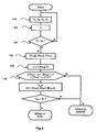
- the voltage V A, V B , V C of each phase is measured on the LV network 15, 25, 35, as well as the voltage of the neutral V N ; the inverse symmetrical component V i is determined by the adapted formula. If the reverse voltage V i does not exceed a tripping threshold S d , no fault is detected in the network directly feeding the start, and the measurements resume at a defined interval, for continuous monitoring.
- the amplitudes ⁇ V XN ⁇ of the voltages are determined for each phase X and their arithmetic mean ⁇ calculated. If at least two norm values ⁇ V XN ⁇ exceed the mean ⁇ , then the fault 7 is upstream of the measuring point 300. Otherwise, the minimum value V min of the amplitudes of phase voltages ⁇ V XN ⁇ is calculated, and if this minimum value V min exceeds a threshold S v set for example at 5% of the nominal value of the network, the fault 7 is upstream of the measuring point 300, otherwise, it is downstream.
- RMS Root Mean Square
- the location of the defect 7 downstream of the measurement point concerns as much a sound departure 15 as a transformer 20 located in the line in default.
- it is easy then to identify the branch of the network MT 5 in default since it is the only departure for which at least one detector 300 installed does not report a fault.
- a defect is located L between two measurement points, one meeting all the above criteria and the other not.
- the result D, L can be indicated either directly at the transformer stations, by lighting diodes, in particular of different color, or via a centralized system of the report type in a functional diagram of the network 1, for example by remote signaling to a center control.
- Detection means 50 of the voltage sensor type are therefore implemented on each LV feeder, in particular at the LV level of the transformers 10, 20, 30 fed by the MV network 5. They are associated with a monitoring system of the MV network , comprising directional detection devices 100, 200, 300 for processing the information of each departure, said devices 100, 200, 300 being able to be integrated into each transformer 10, 20, 30 or be part of a central system to which the information of each sensor 50 is transmitted.
- the data of these directional detection devices 100, 200, 300 will make it possible to identify the relative location of the fault between two devices.
- FIG. figure 4 A preferred embodiment of a device adapted to implement the method according to the invention is illustrated in FIG. figure 4 .
- the directional detection device comprises means 110 making it possible to obtain signals representative of the phase voltages V A, V B , V C , V N provided by the sensors 50 and received by suitable means of the device 100.
- the signals advantageously filtered by means 112 adapted as an analog filter, V Af , V Bf , V Cf , V Nf are further conditioned and the means for obtaining the representative signals 110 comprise a sampling module 114, operating in particular at more than 1 kHz, thus providing filtered sample signals V Af *, V Bf *, V Cf * to complex phasor calculator means 116 for obtaining phase voltages V AN , V BN , V CN .
- the neutral of the LV network is not distributed, the use of phase-to-phase voltage measurements U AB , U BC , U CA makes it possible to reconstitute an artificial neutral by transformation of a star triangle.
- the signals V XN originating from the obtaining means 110 are transmitted to a detection block 120 of a fault 7, which comprises in particular means 122 for determining at least one V i of the symmetrical components of the voltage, in particular by via a Fortescue matrix.
- is determined by the appropriate means 124.
- the detection unit 120 comprises means 126 for comparing the module of the reverse voltage
- means 128 are provided for setting the triggering threshold S d , in particular between 4 and 20% of the nominal value in France.
- the processing block 130 receives the signals V AN , V BN , V CN from the obtaining means 110. It comprises means of calculation 132 of their standard (or amplitude, rms value or other) ⁇ V AN ⁇ , ⁇ V BN ⁇ , ⁇ V CN ⁇ ; The value obtained is transmitted to first comparison means 134 of the minimum of the norm V min with a threshold S v . In parallel, the standards obtained ⁇ V AN ⁇ , ⁇ V BN ⁇ , ⁇ V CN ⁇ are transmitted successively to means calculation 136 of the arithmetic mean ⁇ of the three data inputs, and second comparison means 138, which comprise a fourth input corresponding to the calculated average ⁇ .
- the comparison means 132, 138 are connected to interpretation means 140 whose output is a signal L directional earth fault detection downstream or upstream of the sensors 50 according to the result of the interpretation.
- the second comparison means 138 compare each of the norm values ⁇ V XN ⁇ with their mean ⁇ and advantageously give a binary signal according to the direction of comparison with the interpretation means 140; in a preferred embodiment, the interpretation means 140 or the second comparison means 138 comprise means for summing the binary results of the comparison.
- the elements 110, 120, 130 of the directional detection device can be grouped together in an apparatus, which can for example be coupled to four sensors 50 and located in an MT / LV transformer station; they can also be separated, with for example the means of obtaining 110 associated with the sensors 50 within a transformer station, and the detection and processing blocks integrated in a control unit, the phase voltages being transmitted to these blocks automatically or not.
- each of the blocks 110, 120, 130 can be able to process a starting plurality, simultaneously or in sequence, and to include appropriate storage memories.
- means for measuring the voltage of each conductor are set up on the LV feeders, preferably at each transformer powered by the MV network to be monitored.
- the measuring means are adapted to measure the voltage of each phase and the voltage of the neutral; the signals obtained are transmitted to one or more detection devices which are able to determine the resulting inverse voltage as well as the amplitude.
- the solution according to the invention has the advantage of considering the problem of MV conductor breakage from the point of view of the voltages in the LV network in which the measurement instrumentation is simpler, and considering in a comprehensive manner. all possible situations for one or two broken conductors (for a three-phase network).
- the system or method according to the invention may be associated with network protection devices 5, for example a protection relay which triggers and isolates the branch of the faulty network when a fault is detected in said branch.
- network protection devices 5 for example a protection relay which triggers and isolates the branch of the faulty network when a fault is detected in said branch.
- deferred signaling alone can be envisaged, for example by means of an event log.
- any type of direct signaling, local or remote, immediate or deferred, or any type of more radical action can be associated with the detection according to the invention.
- the invention finds the same application and the same embodiments for a network that is partially or totally underground, in which the breaks in cables can occur due to insulation damage or breakage of other elements may be affected by the invention.
- the elements presented to perform the above functions may be replaced by equivalents: in particular, the voltage may be measured by any type of sensor (resistive, capacitive, electric field, ...), and the signal processing means can take adapted forms, in particular for calculating the reverse voltage.
Landscapes
- Testing Of Short-Circuits, Discontinuities, Leakage, Or Incorrect Line Connections (AREA)
- Locating Faults (AREA)
- Remote Monitoring And Control Of Power-Distribution Networks (AREA)
Priority Applications (1)
| Application Number | Priority Date | Filing Date | Title |
|---|---|---|---|
| PL12354028T PL2533060T3 (pl) | 2011-06-07 | 2012-04-27 | Wykrywanie, z uwzględnieniem kierunku, zwarcia rezystancyjnego doziemnego i przerwania przewodu średniego napięcia |
Applications Claiming Priority (1)
| Application Number | Priority Date | Filing Date | Title |
|---|---|---|---|
| FR1101730A FR2976363B1 (fr) | 2011-06-07 | 2011-06-07 | Detection directionnelle de defaut terre resistant et de rupture de conducteur moyenne tension |
Publications (2)
| Publication Number | Publication Date |
|---|---|
| EP2533060A1 EP2533060A1 (fr) | 2012-12-12 |
| EP2533060B1 true EP2533060B1 (fr) | 2014-07-30 |
Family
ID=46027881
Family Applications (1)
| Application Number | Title | Priority Date | Filing Date |
|---|---|---|---|
| EP12354028.8A Active EP2533060B1 (fr) | 2011-06-07 | 2012-04-27 | Détection directionnelle de défaut à la terre résistant et de rupture de conducteur moyenne tension |
Country Status (7)
| Country | Link |
|---|---|
| EP (1) | EP2533060B1 (pl) |
| CN (1) | CN102818969B (pl) |
| AU (1) | AU2012203278B2 (pl) |
| ES (1) | ES2511644T3 (pl) |
| FR (1) | FR2976363B1 (pl) |
| PL (1) | PL2533060T3 (pl) |
| RU (1) | RU2583452C2 (pl) |
Families Citing this family (12)
| Publication number | Priority date | Publication date | Assignee | Title |
|---|---|---|---|---|
| FR2993670B1 (fr) | 2012-07-20 | 2014-07-11 | Schneider Electric Ind Sas | Detection directionnelle de defaut terre sensible moyenne tension par correlation lineaire |
| CN103698647B (zh) * | 2013-12-23 | 2016-06-22 | 广东电网公司茂名供电局 | 一种电力系统单相接地故障的自动检测方法 |
| FR3023444B1 (fr) | 2014-07-02 | 2018-02-16 | Schneider Electric Industries Sas | Module d'alimentation pour equipement modulaire de tele-conduite et equipement le comprenant |
| FR3023429A1 (fr) | 2014-07-02 | 2016-01-08 | Schneider Electric Ind Sas | Equipement modulaire de tele-conduite |
| FR3026492B1 (fr) * | 2014-09-29 | 2016-10-28 | Schneider Electric Ind Sas | Detection directionnelle de defaut terre dans un reseau de distribution electrique |
| CN105589008B (zh) * | 2014-11-18 | 2019-02-19 | 德信东源电力技术服务(北京)有限公司 | 断相故障检测方法及装置 |
| CN105738767B (zh) * | 2016-02-26 | 2018-03-27 | 李景禄 | 一种分区式配电网单相过渡电阻接地故障选相法 |
| TWI641854B (zh) * | 2017-06-23 | 2018-11-21 | 宏碁股份有限公司 | 故障警示電路 |
| CN108051696A (zh) * | 2017-12-11 | 2018-05-18 | 李玉诚 | 一种用于检测装置连接状态的检测方法 |
| CN108717151A (zh) * | 2018-05-31 | 2018-10-30 | 佛山市梅雨科技有限公司 | 一种电网故障检测系统 |
| FR3083322B1 (fr) * | 2018-06-28 | 2021-06-25 | Electricite De France | Systeme et procede de localisation de defaut sur un reseau electrique poliphase utilisant l'evolution de tension directe et inverse |
| CN115792600B (zh) * | 2022-09-29 | 2024-09-06 | 华能国际电力股份有限公司上海石洞口第二电厂 | 一种电动机三相电流测量误差自动报警方法及装置 |
Family Cites Families (10)
| Publication number | Priority date | Publication date | Assignee | Title |
|---|---|---|---|---|
| US5343155A (en) * | 1991-12-20 | 1994-08-30 | The Research And Development Institute, Inc. At Montana State University | Fault detection and location system for power transmission and distribution lines |
| CN1494658A (zh) * | 2000-11-08 | 2004-05-05 | 通用电气公司 | 检测和计算接地故障电阻的设备和方法 |
| US7099130B2 (en) * | 2003-01-17 | 2006-08-29 | Ericson Manufacturing Company | Voltage monitor for ground fault circuit interrupter |
| SI21482A (sl) * | 2004-06-01 | 2004-10-31 | Marjan Bezjak | Naprava za odkrivanje in izklop prekinjenega polizoliranega vodnika v električnih vodih srednje napetosti |
| IES20050382A2 (en) * | 2004-06-04 | 2005-12-14 | Fmc Tech Ltd | A method of monitoring line faults in a medium voltage network |
| DE102005028881B4 (de) * | 2005-06-22 | 2010-04-29 | Siemens Ag | Fehlerstromanalysator zur Erfassung eines Fehlerstroms und Einrichtung mit Fehlerstromerfassungsfunktion |
| CN101452039A (zh) * | 2007-11-29 | 2009-06-10 | 上海蓝瑞电气有限公司 | 一种用于中压配电网的接地故障综合诊断装置 |
| RU2374733C1 (ru) * | 2008-11-27 | 2009-11-27 | Владимир Григорьевич Наровлянский | Способ определения короткого замыкания в электроэнергетической системе |
| CN101858948B (zh) * | 2009-04-10 | 2015-01-28 | 阿海珐输配电英国有限公司 | 用于在三相中压配电系统中进行暂态和间歇性接地故障检测和方向确定的方法和系统 |
| CN101871989A (zh) * | 2009-04-23 | 2010-10-27 | 上海市南供电设计有限公司 | 一种用于中压配电网接地故障诊断的电压、电流调理装置 |
-
2011
- 2011-06-07 FR FR1101730A patent/FR2976363B1/fr not_active Expired - Fee Related
-
2012
- 2012-04-27 PL PL12354028T patent/PL2533060T3/pl unknown
- 2012-04-27 EP EP12354028.8A patent/EP2533060B1/fr active Active
- 2012-04-27 ES ES12354028.8T patent/ES2511644T3/es active Active
- 2012-06-04 AU AU2012203278A patent/AU2012203278B2/en active Active
- 2012-06-06 RU RU2012123514/07A patent/RU2583452C2/ru active
- 2012-06-07 CN CN201210186466.6A patent/CN102818969B/zh active Active
Also Published As
| Publication number | Publication date |
|---|---|
| CN102818969A (zh) | 2012-12-12 |
| CN102818969B (zh) | 2017-06-09 |
| PL2533060T3 (pl) | 2014-11-28 |
| FR2976363A1 (fr) | 2012-12-14 |
| RU2583452C2 (ru) | 2016-05-10 |
| ES2511644T3 (es) | 2014-10-23 |
| RU2012123514A (ru) | 2013-12-20 |
| AU2012203278B2 (en) | 2014-07-10 |
| FR2976363B1 (fr) | 2013-05-24 |
| AU2012203278A1 (en) | 2013-01-10 |
| EP2533060A1 (fr) | 2012-12-12 |
Similar Documents
| Publication | Publication Date | Title |
|---|---|---|
| EP2533060B1 (fr) | Détection directionnelle de défaut à la terre résistant et de rupture de conducteur moyenne tension | |
| US9182431B2 (en) | Method and apparatus for determining an insulation resistance in a grounded isole terre system | |
| EP3814788B1 (fr) | Systeme et procede de localisation de defaut sur un reseau electrique poliphase utilisant l'evolution de tension directe et inverse | |
| EP2648008B1 (fr) | Système de contrôle d'isolement pour réseau électrique sécurisé | |
| EP2741390B1 (fr) | Détection directionnelle d'un défaut, notamment dans un réseau à neutre compensé ou isolé | |
| EP1890165B1 (fr) | Procédé de détection directionnel d'un défaut à la terre et dispositif pour sa mise en oeuvre | |
| EP2687860B1 (fr) | Détection directionnelle de défaut terre sensible moyenne tension par corrélation linéaire | |
| EP2383856B1 (fr) | Identification et détection directionnelle d'un défaut dans un reseau triphase | |
| EP2421110B1 (fr) | Detection directionnelle d'un defaut à la terre avec un seul capteur | |
| EP3707521B1 (fr) | Procede de detection de l'etat d'un appareil de protection electrique dans une installation electrique et dispositif de detection mettant en oeuvre ledit procede | |
| EP2731220B1 (fr) | Dispositif et procédé de détermination de la tension et de la puissance de chaque phase dans un réseau moyenne tension | |
| EP2169799A2 (fr) | Détection directionnelle d'un défaut à la terre | |
| EP3106887B1 (fr) | Procede et dispositif de detection d'un defaut dans un reseau electrique | |
| CA2862849C (fr) | Dispositif et procede de securite pour installation electrique | |
| FR2936378A1 (fr) | Detection directionnelle d'un defaut a la terre a faible echantillonnage | |
| EP2910958A1 (fr) | Détection d'un défaut, notamment transitoire, dans un réseau électrique | |
| FR3105430A1 (fr) | Dispositif de detection d'une defaillance dans un reseau electrique, reseau electrique ou equipement comprenant un tel dispositif et procede de detection d’une defaillance | |
| FR2922028A1 (fr) | Localisation d'un defaut dans un reseau de distribution publique moyenne tension | |
| EP3798648B1 (fr) | Procédé de détermination d'une position d'un précurseur de défaut dans un câble haute tension en fonctionnement | |
| EP2863232A1 (fr) | Procédé de détermination d'une consommation individuelle de puissance | |
| FR2969845A1 (fr) | Dispositif et procede de protection terre restreinte | |
| EP4184181B1 (fr) | Système de détermination de présence de tension pour un réseau électrique haute tension | |
| FR3033198A1 (fr) | Systeme de surveillance d’une ligne haute tension a courant continu | |
| FR2999294A1 (fr) | Detection directionnelle d'un defaut, notamment dans un reseau a neutre compense | |
| FR2815720A1 (fr) | Systeme de detection d'arrachement de cables dans les reseaux moyenne tension, et procede de modification d'un systeme existant |
Legal Events
| Date | Code | Title | Description |
|---|---|---|---|
| PUAI | Public reference made under article 153(3) epc to a published international application that has entered the european phase |
Free format text: ORIGINAL CODE: 0009012 |
|
| AK | Designated contracting states |
Kind code of ref document: A1 Designated state(s): AL AT BE BG CH CY CZ DE DK EE ES FI FR GB GR HR HU IE IS IT LI LT LU LV MC MK MT NL NO PL PT RO RS SE SI SK SM TR |
|
| AX | Request for extension of the european patent |
Extension state: BA ME |
|
| 17P | Request for examination filed |
Effective date: 20130112 |
|
| GRAP | Despatch of communication of intention to grant a patent |
Free format text: ORIGINAL CODE: EPIDOSNIGR1 |
|
| RIC1 | Information provided on ipc code assigned before grant |
Ipc: G01R 31/02 20060101AFI20140225BHEP Ipc: H02H 5/10 20060101ALI20140225BHEP Ipc: H02H 1/00 20060101ALI20140225BHEP |
|
| INTG | Intention to grant announced |
Effective date: 20140328 |
|
| GRAS | Grant fee paid |
Free format text: ORIGINAL CODE: EPIDOSNIGR3 |
|
| GRAA | (expected) grant |
Free format text: ORIGINAL CODE: 0009210 |
|
| AK | Designated contracting states |
Kind code of ref document: B1 Designated state(s): AL AT BE BG CH CY CZ DE DK EE ES FI FR GB GR HR HU IE IS IT LI LT LU LV MC MK MT NL NO PL PT RO RS SE SI SK SM TR |
|
| REG | Reference to a national code |
Ref country code: GB Ref legal event code: FG4D Free format text: NOT ENGLISH |
|
| REG | Reference to a national code |
Ref country code: CH Ref legal event code: EP |
|
| REG | Reference to a national code |
Ref country code: AT Ref legal event code: REF Ref document number: 680217 Country of ref document: AT Kind code of ref document: T Effective date: 20140815 |
|
| REG | Reference to a national code |
Ref country code: IE Ref legal event code: FG4D Free format text: LANGUAGE OF EP DOCUMENT: FRENCH |
|
| REG | Reference to a national code |
Ref country code: DE Ref legal event code: R096 Ref document number: 602012002590 Country of ref document: DE Effective date: 20140911 |
|
| REG | Reference to a national code |
Ref country code: ES Ref legal event code: FG2A Ref document number: 2511644 Country of ref document: ES Kind code of ref document: T3 Effective date: 20141023 |
|
| REG | Reference to a national code |
Ref country code: PL Ref legal event code: T3 |
|
| REG | Reference to a national code |
Ref country code: AT Ref legal event code: MK05 Ref document number: 680217 Country of ref document: AT Kind code of ref document: T Effective date: 20140730 |
|
| REG | Reference to a national code |
Ref country code: NL Ref legal event code: VDEP Effective date: 20140730 |
|
| REG | Reference to a national code |
Ref country code: LT Ref legal event code: MG4D |
|
| PG25 | Lapsed in a contracting state [announced via postgrant information from national office to epo] |
Ref country code: PT Free format text: LAPSE BECAUSE OF FAILURE TO SUBMIT A TRANSLATION OF THE DESCRIPTION OR TO PAY THE FEE WITHIN THE PRESCRIBED TIME-LIMIT Effective date: 20141202 Ref country code: NO Free format text: LAPSE BECAUSE OF FAILURE TO SUBMIT A TRANSLATION OF THE DESCRIPTION OR TO PAY THE FEE WITHIN THE PRESCRIBED TIME-LIMIT Effective date: 20141030 Ref country code: SE Free format text: LAPSE BECAUSE OF FAILURE TO SUBMIT A TRANSLATION OF THE DESCRIPTION OR TO PAY THE FEE WITHIN THE PRESCRIBED TIME-LIMIT Effective date: 20140730 Ref country code: BG Free format text: LAPSE BECAUSE OF FAILURE TO SUBMIT A TRANSLATION OF THE DESCRIPTION OR TO PAY THE FEE WITHIN THE PRESCRIBED TIME-LIMIT Effective date: 20141030 Ref country code: LT Free format text: LAPSE BECAUSE OF FAILURE TO SUBMIT A TRANSLATION OF THE DESCRIPTION OR TO PAY THE FEE WITHIN THE PRESCRIBED TIME-LIMIT Effective date: 20140730 Ref country code: FI Free format text: LAPSE BECAUSE OF FAILURE TO SUBMIT A TRANSLATION OF THE DESCRIPTION OR TO PAY THE FEE WITHIN THE PRESCRIBED TIME-LIMIT Effective date: 20140730 Ref country code: GR Free format text: LAPSE BECAUSE OF FAILURE TO SUBMIT A TRANSLATION OF THE DESCRIPTION OR TO PAY THE FEE WITHIN THE PRESCRIBED TIME-LIMIT Effective date: 20141031 |
|
| PG25 | Lapsed in a contracting state [announced via postgrant information from national office to epo] |
Ref country code: AT Free format text: LAPSE BECAUSE OF FAILURE TO SUBMIT A TRANSLATION OF THE DESCRIPTION OR TO PAY THE FEE WITHIN THE PRESCRIBED TIME-LIMIT Effective date: 20140730 Ref country code: RS Free format text: LAPSE BECAUSE OF FAILURE TO SUBMIT A TRANSLATION OF THE DESCRIPTION OR TO PAY THE FEE WITHIN THE PRESCRIBED TIME-LIMIT Effective date: 20140730 Ref country code: NL Free format text: LAPSE BECAUSE OF FAILURE TO SUBMIT A TRANSLATION OF THE DESCRIPTION OR TO PAY THE FEE WITHIN THE PRESCRIBED TIME-LIMIT Effective date: 20140730 Ref country code: LV Free format text: LAPSE BECAUSE OF FAILURE TO SUBMIT A TRANSLATION OF THE DESCRIPTION OR TO PAY THE FEE WITHIN THE PRESCRIBED TIME-LIMIT Effective date: 20140730 Ref country code: HR Free format text: LAPSE BECAUSE OF FAILURE TO SUBMIT A TRANSLATION OF THE DESCRIPTION OR TO PAY THE FEE WITHIN THE PRESCRIBED TIME-LIMIT Effective date: 20140730 Ref country code: IS Free format text: LAPSE BECAUSE OF FAILURE TO SUBMIT A TRANSLATION OF THE DESCRIPTION OR TO PAY THE FEE WITHIN THE PRESCRIBED TIME-LIMIT Effective date: 20141130 Ref country code: CY Free format text: LAPSE BECAUSE OF FAILURE TO SUBMIT A TRANSLATION OF THE DESCRIPTION OR TO PAY THE FEE WITHIN THE PRESCRIBED TIME-LIMIT Effective date: 20140730 |
|
| PG25 | Lapsed in a contracting state [announced via postgrant information from national office to epo] |
Ref country code: EE Free format text: LAPSE BECAUSE OF FAILURE TO SUBMIT A TRANSLATION OF THE DESCRIPTION OR TO PAY THE FEE WITHIN THE PRESCRIBED TIME-LIMIT Effective date: 20140730 Ref country code: SK Free format text: LAPSE BECAUSE OF FAILURE TO SUBMIT A TRANSLATION OF THE DESCRIPTION OR TO PAY THE FEE WITHIN THE PRESCRIBED TIME-LIMIT Effective date: 20140730 Ref country code: CZ Free format text: LAPSE BECAUSE OF FAILURE TO SUBMIT A TRANSLATION OF THE DESCRIPTION OR TO PAY THE FEE WITHIN THE PRESCRIBED TIME-LIMIT Effective date: 20140730 Ref country code: IT Free format text: LAPSE BECAUSE OF FAILURE TO SUBMIT A TRANSLATION OF THE DESCRIPTION OR TO PAY THE FEE WITHIN THE PRESCRIBED TIME-LIMIT Effective date: 20140730 Ref country code: DK Free format text: LAPSE BECAUSE OF FAILURE TO SUBMIT A TRANSLATION OF THE DESCRIPTION OR TO PAY THE FEE WITHIN THE PRESCRIBED TIME-LIMIT Effective date: 20140730 Ref country code: RO Free format text: LAPSE BECAUSE OF FAILURE TO SUBMIT A TRANSLATION OF THE DESCRIPTION OR TO PAY THE FEE WITHIN THE PRESCRIBED TIME-LIMIT Effective date: 20140730 |
|
| REG | Reference to a national code |
Ref country code: DE Ref legal event code: R097 Ref document number: 602012002590 Country of ref document: DE |
|
| PLBE | No opposition filed within time limit |
Free format text: ORIGINAL CODE: 0009261 |
|
| STAA | Information on the status of an ep patent application or granted ep patent |
Free format text: STATUS: NO OPPOSITION FILED WITHIN TIME LIMIT |
|
| 26N | No opposition filed |
Effective date: 20150504 |
|
| PG25 | Lapsed in a contracting state [announced via postgrant information from national office to epo] |
Ref country code: LU Free format text: LAPSE BECAUSE OF FAILURE TO SUBMIT A TRANSLATION OF THE DESCRIPTION OR TO PAY THE FEE WITHIN THE PRESCRIBED TIME-LIMIT Effective date: 20150427 Ref country code: MC Free format text: LAPSE BECAUSE OF FAILURE TO SUBMIT A TRANSLATION OF THE DESCRIPTION OR TO PAY THE FEE WITHIN THE PRESCRIBED TIME-LIMIT Effective date: 20140730 Ref country code: SI Free format text: LAPSE BECAUSE OF FAILURE TO SUBMIT A TRANSLATION OF THE DESCRIPTION OR TO PAY THE FEE WITHIN THE PRESCRIBED TIME-LIMIT Effective date: 20140730 |
|
| REG | Reference to a national code |
Ref country code: CH Ref legal event code: PL |
|
| REG | Reference to a national code |
Ref country code: IE Ref legal event code: MM4A |
|
| PG25 | Lapsed in a contracting state [announced via postgrant information from national office to epo] |
Ref country code: CH Free format text: LAPSE BECAUSE OF NON-PAYMENT OF DUE FEES Effective date: 20150430 Ref country code: LI Free format text: LAPSE BECAUSE OF NON-PAYMENT OF DUE FEES Effective date: 20150430 |
|
| REG | Reference to a national code |
Ref country code: FR Ref legal event code: PLFP Year of fee payment: 5 |
|
| PG25 | Lapsed in a contracting state [announced via postgrant information from national office to epo] |
Ref country code: IE Free format text: LAPSE BECAUSE OF NON-PAYMENT OF DUE FEES Effective date: 20150427 |
|
| PG25 | Lapsed in a contracting state [announced via postgrant information from national office to epo] |
Ref country code: MT Free format text: LAPSE BECAUSE OF FAILURE TO SUBMIT A TRANSLATION OF THE DESCRIPTION OR TO PAY THE FEE WITHIN THE PRESCRIBED TIME-LIMIT Effective date: 20140730 |
|
| REG | Reference to a national code |
Ref country code: FR Ref legal event code: PLFP Year of fee payment: 6 |
|
| PG25 | Lapsed in a contracting state [announced via postgrant information from national office to epo] |
Ref country code: HU Free format text: LAPSE BECAUSE OF FAILURE TO SUBMIT A TRANSLATION OF THE DESCRIPTION OR TO PAY THE FEE WITHIN THE PRESCRIBED TIME-LIMIT; INVALID AB INITIO Effective date: 20120427 Ref country code: SM Free format text: LAPSE BECAUSE OF FAILURE TO SUBMIT A TRANSLATION OF THE DESCRIPTION OR TO PAY THE FEE WITHIN THE PRESCRIBED TIME-LIMIT Effective date: 20140730 |
|
| PG25 | Lapsed in a contracting state [announced via postgrant information from national office to epo] |
Ref country code: BE Free format text: LAPSE BECAUSE OF NON-PAYMENT OF DUE FEES Effective date: 20150430 |
|
| PG25 | Lapsed in a contracting state [announced via postgrant information from national office to epo] |
Ref country code: TR Free format text: LAPSE BECAUSE OF FAILURE TO SUBMIT A TRANSLATION OF THE DESCRIPTION OR TO PAY THE FEE WITHIN THE PRESCRIBED TIME-LIMIT Effective date: 20140730 |
|
| REG | Reference to a national code |
Ref country code: FR Ref legal event code: PLFP Year of fee payment: 7 |
|
| PG25 | Lapsed in a contracting state [announced via postgrant information from national office to epo] |
Ref country code: MK Free format text: LAPSE BECAUSE OF FAILURE TO SUBMIT A TRANSLATION OF THE DESCRIPTION OR TO PAY THE FEE WITHIN THE PRESCRIBED TIME-LIMIT Effective date: 20140730 |
|
| PG25 | Lapsed in a contracting state [announced via postgrant information from national office to epo] |
Ref country code: AL Free format text: LAPSE BECAUSE OF FAILURE TO SUBMIT A TRANSLATION OF THE DESCRIPTION OR TO PAY THE FEE WITHIN THE PRESCRIBED TIME-LIMIT Effective date: 20140730 |
|
| REG | Reference to a national code |
Ref country code: DE Ref legal event code: R079 Ref document number: 602012002590 Country of ref document: DE Free format text: PREVIOUS MAIN CLASS: G01R0031020000 Ipc: G01R0031500000 |
|
| PGFP | Annual fee paid to national office [announced via postgrant information from national office to epo] |
Ref country code: PL Payment date: 20250422 Year of fee payment: 14 Ref country code: DE Payment date: 20250428 Year of fee payment: 14 |
|
| PGFP | Annual fee paid to national office [announced via postgrant information from national office to epo] |
Ref country code: ES Payment date: 20250513 Year of fee payment: 14 Ref country code: GB Payment date: 20250422 Year of fee payment: 14 |
|
| PGFP | Annual fee paid to national office [announced via postgrant information from national office to epo] |
Ref country code: FR Payment date: 20250424 Year of fee payment: 14 |