EP2533301A2 - Système de cellules solaires sur toiture avec une multitude de modules solaires - Google Patents
Système de cellules solaires sur toiture avec une multitude de modules solaires Download PDFInfo
- Publication number
- EP2533301A2 EP2533301A2 EP12163545A EP12163545A EP2533301A2 EP 2533301 A2 EP2533301 A2 EP 2533301A2 EP 12163545 A EP12163545 A EP 12163545A EP 12163545 A EP12163545 A EP 12163545A EP 2533301 A2 EP2533301 A2 EP 2533301A2
- Authority
- EP
- European Patent Office
- Prior art keywords
- solar
- solar cell
- roof system
- cell roof
- module
- Prior art date
- Legal status (The legal status is an assumption and is not a legal conclusion. Google has not performed a legal analysis and makes no representation as to the accuracy of the status listed.)
- Withdrawn
Links
- 239000003570 air Substances 0.000 claims abstract 9
- 239000012080 ambient air Substances 0.000 claims abstract 2
- XLYOFNOQVPJJNP-UHFFFAOYSA-N water Substances O XLYOFNOQVPJJNP-UHFFFAOYSA-N 0.000 claims description 7
- 230000015572 biosynthetic process Effects 0.000 claims description 3
- 238000005755 formation reaction Methods 0.000 claims description 3
- 239000005871 repellent Substances 0.000 claims description 2
- 238000013022 venting Methods 0.000 claims description 2
- 230000002265 prevention Effects 0.000 claims 1
- 230000002940 repellent Effects 0.000 claims 1
- 238000009423 ventilation Methods 0.000 description 2
- 230000007423 decrease Effects 0.000 description 1
- 230000001419 dependent effect Effects 0.000 description 1
- 238000011161 development Methods 0.000 description 1
- 230000018109 developmental process Effects 0.000 description 1
- 230000000694 effects Effects 0.000 description 1
- 238000010438 heat treatment Methods 0.000 description 1
- 238000009434 installation Methods 0.000 description 1
- 238000000034 method Methods 0.000 description 1
- 230000035515 penetration Effects 0.000 description 1
- 238000001556 precipitation Methods 0.000 description 1
- 230000000630 rising effect Effects 0.000 description 1
- 238000007789 sealing Methods 0.000 description 1
Images



Classifications
-
- H—ELECTRICITY
- H10—SEMICONDUCTOR DEVICES; ELECTRIC SOLID-STATE DEVICES NOT OTHERWISE PROVIDED FOR
- H10F—INORGANIC SEMICONDUCTOR DEVICES SENSITIVE TO INFRARED RADIATION, LIGHT, ELECTROMAGNETIC RADIATION OF SHORTER WAVELENGTH OR CORPUSCULAR RADIATION
- H10F77/00—Constructional details of devices covered by this subclass
- H10F77/60—Arrangements for cooling, heating, ventilating or compensating for temperature fluctuations
- H10F77/63—Arrangements for cooling directly associated or integrated with photovoltaic cells, e.g. heat sinks directly associated with the photovoltaic cells or integrated Peltier elements for active cooling
- H10F77/68—Arrangements for cooling directly associated or integrated with photovoltaic cells, e.g. heat sinks directly associated with the photovoltaic cells or integrated Peltier elements for active cooling using gaseous or liquid coolants, e.g. air flow ventilation or water circulation
-
- H—ELECTRICITY
- H02—GENERATION; CONVERSION OR DISTRIBUTION OF ELECTRIC POWER
- H02S—GENERATION OF ELECTRIC POWER BY CONVERSION OF INFRARED RADIATION, VISIBLE LIGHT OR ULTRAVIOLET LIGHT, e.g. USING PHOTOVOLTAIC [PV] MODULES
- H02S20/00—Supporting structures for PV modules
- H02S20/20—Supporting structures directly fixed to an immovable object
- H02S20/22—Supporting structures directly fixed to an immovable object specially adapted for buildings
- H02S20/23—Supporting structures directly fixed to an immovable object specially adapted for buildings specially adapted for roof structures
-
- H—ELECTRICITY
- H02—GENERATION; CONVERSION OR DISTRIBUTION OF ELECTRIC POWER
- H02S—GENERATION OF ELECTRIC POWER BY CONVERSION OF INFRARED RADIATION, VISIBLE LIGHT OR ULTRAVIOLET LIGHT, e.g. USING PHOTOVOLTAIC [PV] MODULES
- H02S20/00—Supporting structures for PV modules
- H02S20/20—Supporting structures directly fixed to an immovable object
- H02S20/22—Supporting structures directly fixed to an immovable object specially adapted for buildings
- H02S20/26—Building materials integrated with PV modules, e.g. façade elements
-
- H—ELECTRICITY
- H02—GENERATION; CONVERSION OR DISTRIBUTION OF ELECTRIC POWER
- H02S—GENERATION OF ELECTRIC POWER BY CONVERSION OF INFRARED RADIATION, VISIBLE LIGHT OR ULTRAVIOLET LIGHT, e.g. USING PHOTOVOLTAIC [PV] MODULES
- H02S30/00—Structural details of PV modules other than those related to light conversion
- H02S30/10—Frame structures
-
- F—MECHANICAL ENGINEERING; LIGHTING; HEATING; WEAPONS; BLASTING
- F24—HEATING; RANGES; VENTILATING
- F24S—SOLAR HEAT COLLECTORS; SOLAR HEAT SYSTEMS
- F24S20/00—Solar heat collectors specially adapted for particular uses or environments
- F24S2020/10—Solar modules layout; Modular arrangements
- F24S2020/13—Overlaying arrangements similar to roof tiles
-
- Y—GENERAL TAGGING OF NEW TECHNOLOGICAL DEVELOPMENTS; GENERAL TAGGING OF CROSS-SECTIONAL TECHNOLOGIES SPANNING OVER SEVERAL SECTIONS OF THE IPC; TECHNICAL SUBJECTS COVERED BY FORMER USPC CROSS-REFERENCE ART COLLECTIONS [XRACs] AND DIGESTS
- Y02—TECHNOLOGIES OR APPLICATIONS FOR MITIGATION OR ADAPTATION AGAINST CLIMATE CHANGE
- Y02B—CLIMATE CHANGE MITIGATION TECHNOLOGIES RELATED TO BUILDINGS, e.g. HOUSING, HOUSE APPLIANCES OR RELATED END-USER APPLICATIONS
- Y02B10/00—Integration of renewable energy sources in buildings
- Y02B10/10—Photovoltaic [PV]
-
- Y—GENERAL TAGGING OF NEW TECHNOLOGICAL DEVELOPMENTS; GENERAL TAGGING OF CROSS-SECTIONAL TECHNOLOGIES SPANNING OVER SEVERAL SECTIONS OF THE IPC; TECHNICAL SUBJECTS COVERED BY FORMER USPC CROSS-REFERENCE ART COLLECTIONS [XRACs] AND DIGESTS
- Y02—TECHNOLOGIES OR APPLICATIONS FOR MITIGATION OR ADAPTATION AGAINST CLIMATE CHANGE
- Y02E—REDUCTION OF GREENHOUSE GAS [GHG] EMISSIONS, RELATED TO ENERGY GENERATION, TRANSMISSION OR DISTRIBUTION
- Y02E10/00—Energy generation through renewable energy sources
- Y02E10/50—Photovoltaic [PV] energy
Definitions
- the invention relates to a solar cell roof system with a plurality of solar modules, at least some of which are to be mounted on one another for the realization of a rain protection.
- PV modules include solar cells or photoelectrically active layers, which convert light into electrical current. These modules can be aligned on the floor using racks or integrated on rooftops of buildings and in building envelopes. When integrated into the building envelope, the solar modules can take on tasks of this, for example, they can support the weather protection, especially the drainage in the rain.
- Fig. 1 and 2 show two variants of a solar cell roof system in in-roof installation. Both systems are constructed structurally the same and therefore designated in both figures with the numeral 1.
- Each consists of a plurality of solar modules 3, which are inserted roofing overlapping in a roof covering with conventional roofing elements 5 .
- the solar cells 3 and roofing elements 5 are in the manner shown on a battens 7, which in turn are arranged on a sealing skin 9 and an insulating layer 11 on a (not shown) support structure of the roof.
- the execution after Fig. 2 differs from the one after Fig. 1 in that a rear ventilation was realized. In this case, the air enters the bottom module and flows up to the top module behind the modules. This is in Fig. 2 symbolized by arrows L at the bottom of the roof section shown and below the solar cell 3 ; while in Fig. 1 the over the solar modules 3 effluent water symbolized by the arrows W.
- the heated air then has to escape in the upper roof area.
- a solar cell roof system with the features of claim 1 is provided.
- Advantageous developments of the inventive concept are the subject of the dependent claims.
- the term "roof system” should also include façade systems that take on the tasks of a building envelope outside a roof, in particular the weather protection.
- the air guiding means according to the invention are provided in the lower edge and the opposite upper edge of the solar module. Furthermore, in particular the air guidance means are each formed in or near a frame part of the solar module.
- the air guidance means comprise a cutout in the frame part, in particular in each case a cutout in a lower edge frame part and an upper edge frame part, of the solar module.
- the air guiding means are each assigned Wasserabweissch for rejection of emerging water.
- the water-repellent means comprise wedge-shaped formations or wedge-shaped additional parts on an upper edge frame part of the solar module.
- the roof system according to the invention on module connector profiles, which also serve for the correct positioning of the solar modules to be mounted one above the other. Furthermore is provided that the module connector profiles at the same time form the wedge-shaped additional parts.
- the proposed system advantageously includes an end cap for mounting over a solar panel, which includes a V or U-shaped air outlet duct for venting air from behind the back of the corresponding solar module while preventing the ingress of rainwater, and connector means for mounting on an edge of the solar module.
- a suitable solar cell roof system comprises a lower edge connector profile with recesses serving as an air guide means for mounting under a lowermost solar module of the solar cell roof system.
- Fig. 3 shows, based on the representation in Fig. 1 and 2 schematically the structure of a solar cell roof system 1 ' according to the invention , wherein the same or functionally identical parts with the same numbers as in Fig. 1 and Fig. 2 are indicative and will not be explained again here.
- the roof system 1 ' differs con with the roof system 1 Fig. 2 in that not only below the system, ie below the lowermost solar cell module 3 ', an air flow L1 enters behind the solar cell modules, but also at the lower edges of the individual modules or between the upper edge and the lower edge of the module arranged above, additional air streams L2 enter. This is due to an opposite to the arrangement Fig. 2 modified structural design and assembly of the solar cell modules 3 ' with special (in Fig.
- Fig. 4 shows the adjacent edge regions of two solar modules 3 'of a solar cell roof system 1' in Fig. 3 shown in more detail.
- a lower edge frame part 3a ' also has a cutout 3c' as an adjacent upper edge frame part 3b 'of the below adjacent solar cell module, so that an air flow L2 can get between them.
- Connected to the adjacent solar cell modules via a module connector profile 13, on the a plurality of connectors 15 are mounted for electrical connection and mechanical fixing of the respective module.
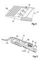
- Fig. 5 shows in a perspective detail view of such a module connector profile 13 and the connector 15 arranged thereon in more detail. It can be seen that the cross section of the profile 13 is flat trapezoidal, so its overall shape is considered to be wedge-shaped. On its upper side, a plurality of small wedge-shaped formations 13a is provided, which in use should largely prevent any rising of precipitation water between the profile 13 and the solar cell module 3 ' mounted thereon behind its rear side.
- Fig. 6 shows the module connector profile 13 with one of the connectors 15 again in cross-section, in its use as a connector means for placing a favorhutze 17 on the upper edge of the solar cell roof system 1 '.
- This end cap 17 serves to guide the outgoing from the back of the solar cell roof system airflow L3 while preventing the ingress of rainwater. It includes a cross-sectionally U-shaped air channel 17 a, which is formed with the involvement of the module connector profile 13 .
- An integrally formed extension 17b ensures a watertight fit under roofing element (not shown) adjoining the top of the solar cell roof system.
- Fig. 7 shows in a perspective detail view as another part of the embodiment of the invention explained here special connector profiles 13 ', which are to be used as the lowest profile of a solar cell roof system and this at the lower edge recesses 13a' , the penetration of an air flow L1 behind the back of the roof system allow from its lower edge.
Landscapes
- Engineering & Computer Science (AREA)
- Architecture (AREA)
- Civil Engineering (AREA)
- Structural Engineering (AREA)
- Roof Covering Using Slabs Or Stiff Sheets (AREA)
- Photovoltaic Devices (AREA)
Applications Claiming Priority (1)
| Application Number | Priority Date | Filing Date | Title |
|---|---|---|---|
| DE102011077229A DE102011077229A1 (de) | 2011-06-08 | 2011-06-08 | Solarzellen-Dachsystem mit einer Mehrzahl von Solarmodulen |
Publications (2)
| Publication Number | Publication Date |
|---|---|
| EP2533301A2 true EP2533301A2 (fr) | 2012-12-12 |
| EP2533301A3 EP2533301A3 (fr) | 2013-05-29 |
Family
ID=46085353
Family Applications (1)
| Application Number | Title | Priority Date | Filing Date |
|---|---|---|---|
| EP12163545.2A Withdrawn EP2533301A3 (fr) | 2011-06-08 | 2012-04-10 | Système de cellules solaires sur toiture avec une multitude de modules solaires |
Country Status (3)
| Country | Link |
|---|---|
| US (1) | US20120312350A1 (fr) |
| EP (1) | EP2533301A3 (fr) |
| DE (1) | DE102011077229A1 (fr) |
Families Citing this family (2)
| Publication number | Priority date | Publication date | Assignee | Title |
|---|---|---|---|---|
| CN104539232A (zh) * | 2015-01-04 | 2015-04-22 | 浙江晶科能源有限公司 | 一种散热型光伏组件 |
| US11543155B2 (en) * | 2019-02-15 | 2023-01-03 | Gregory S. Daniels | Devices and systems for ventilation of solar roofs |
Family Cites Families (8)
| Publication number | Priority date | Publication date | Assignee | Title |
|---|---|---|---|---|
| EP0907209A1 (fr) * | 1997-10-03 | 1999-04-07 | Kämpfer & Co. | Tuile pour toiture |
| US20040221886A1 (en) * | 2003-02-26 | 2004-11-11 | Kyocera Corporation | Solar cell module and solar cell array using same |
| US8276329B2 (en) * | 2005-05-27 | 2012-10-02 | Sunpower Corporation | Fire resistant PV shingle assembly |
| US8701360B2 (en) * | 2007-05-25 | 2014-04-22 | General Electric Company | Method and apparatus for assembling photovoltaic modules |
| US8938919B2 (en) * | 2007-09-21 | 2015-01-27 | Andalay Solar, Inc. | Electrical connectors for solar modules |
| EP2216829A1 (fr) * | 2009-02-10 | 2010-08-11 | Darvan Invest N.V. | Ensemble de tuile de toiture solaire |
| US20100313501A1 (en) * | 2009-06-10 | 2010-12-16 | Gangemi Ronald J | Roof mounting bracket for photovoltaic power generation system |
| WO2011059559A1 (fr) * | 2009-11-16 | 2011-05-19 | Sunpower Corporation | Appareils résistant à l'eau pour modules photovoltaïques |
-
2011
- 2011-06-08 DE DE102011077229A patent/DE102011077229A1/de not_active Withdrawn
-
2012
- 2012-04-10 EP EP12163545.2A patent/EP2533301A3/fr not_active Withdrawn
- 2012-06-07 US US13/491,144 patent/US20120312350A1/en not_active Abandoned
Non-Patent Citations (1)
| Title |
|---|
| None |
Also Published As
| Publication number | Publication date |
|---|---|
| EP2533301A3 (fr) | 2013-05-29 |
| DE102011077229A1 (de) | 2012-12-13 |
| US20120312350A1 (en) | 2012-12-13 |
Similar Documents
| Publication | Publication Date | Title |
|---|---|---|
| EP2242112B1 (fr) | Système de recouvrement de toit pour modules solaires | |
| EP2518421A2 (fr) | Agencement solaire | |
| DE102019112799A1 (de) | Photovoltaikdachpfanne mit Nutzung der Abwärme | |
| DE202015000200U1 (de) | Solardachplattensystem | |
| AT524775B1 (fr) | ||
| DE112014004754T5 (de) | Befestigungsstruktur eines Dünnschicht-Photovoltaikzellenmoduls | |
| WO2017153269A1 (fr) | Tuile photovoltaïque dotée d'une ligne électrique de longueur variable | |
| EP2190030A2 (fr) | Unité photovoltaïque, système photovoltaïque ainsi que procédé de fabrication d'une unité photovoltaïque | |
| DE202008015141U1 (de) | Eindeckung und Solaranlage | |
| EP2533301A2 (fr) | Système de cellules solaires sur toiture avec une multitude de modules solaires | |
| AT523015B1 (de) | Rahmen eines Moduls für ein modulares Photovoltaiksystem, damit hergestelltes Modul und modulares Photovoltaiksystem | |
| DE102005039494B4 (de) | Verwendung einer Photovoltaik-Anlage | |
| DE202010012826U1 (de) | Parkplatzüberdachung mit applizierten Solarmodulen | |
| DE102022207465A1 (de) | Solarmodul und Verfahren zu dessen Montage | |
| EP1873321A2 (fr) | Construction dotée d'au moins un élément solaire comprenant un toit | |
| DE202019002746U1 (de) | Montageprofil für Solarmodule für indach Anlagen | |
| DE202008010046U1 (de) | Metall-Leichtbau-Dachkonstruktion mit integriertem Photovoltaikmodul | |
| DE202013010199U1 (de) | Indach-/Aufdach-Solarsystemanordnung | |
| DE102012102234A1 (de) | Solarmodul-System, Solarmodul-Baukasten und Solarmodul-Anordnung | |
| DE202013002774U1 (de) | Anordnung von flach ausgebildeten Photovoltaikmodulen | |
| DE20013940U1 (de) | Solarmodul | |
| AT525079B1 (de) | Schrägdachaufbau | |
| WO2013186207A1 (fr) | Disposition de modules photovoltaïques de configuration plate | |
| DE102024123778A1 (de) | Befestigungssystem für ein plattenförmiges Bauelement an einer Dachkonstruktion und Modul für ein Dach | |
| EP3648339B1 (fr) | Couverture de toiture solaire |
Legal Events
| Date | Code | Title | Description |
|---|---|---|---|
| PUAI | Public reference made under article 153(3) epc to a published international application that has entered the european phase |
Free format text: ORIGINAL CODE: 0009012 |
|
| AK | Designated contracting states |
Kind code of ref document: A2 Designated state(s): AL AT BE BG CH CY CZ DE DK EE ES FI FR GB GR HR HU IE IS IT LI LT LU LV MC MK MT NL NO PL PT RO RS SE SI SK SM TR |
|
| AX | Request for extension of the european patent |
Extension state: BA ME |
|
| PUAL | Search report despatched |
Free format text: ORIGINAL CODE: 0009013 |
|
| AK | Designated contracting states |
Kind code of ref document: A3 Designated state(s): AL AT BE BG CH CY CZ DE DK EE ES FI FR GB GR HR HU IE IS IT LI LT LU LV MC MK MT NL NO PL PT RO RS SE SI SK SM TR |
|
| AX | Request for extension of the european patent |
Extension state: BA ME |
|
| RIC1 | Information provided on ipc code assigned before grant |
Ipc: H01L 31/052 20060101ALI20130424BHEP Ipc: H01L 31/048 20060101AFI20130424BHEP |
|
| STAA | Information on the status of an ep patent application or granted ep patent |
Free format text: STATUS: THE APPLICATION IS DEEMED TO BE WITHDRAWN |
|
| 18D | Application deemed to be withdrawn |
Effective date: 20131130 |