EP2533408A2 - Stromversorgungsanordnung für einen einendigen Verstärker der Klasse D - Google Patents
Stromversorgungsanordnung für einen einendigen Verstärker der Klasse D Download PDFInfo
- Publication number
- EP2533408A2 EP2533408A2 EP11172638A EP11172638A EP2533408A2 EP 2533408 A2 EP2533408 A2 EP 2533408A2 EP 11172638 A EP11172638 A EP 11172638A EP 11172638 A EP11172638 A EP 11172638A EP 2533408 A2 EP2533408 A2 EP 2533408A2
- Authority
- EP
- European Patent Office
- Prior art keywords
- winding
- primary winding
- flyback
- power supply
- control
- Prior art date
- Legal status (The legal status is an assumption and is not a legal conclusion. Google has not performed a legal analysis and makes no representation as to the accuracy of the status listed.)
- Granted
Links
Images

Classifications
-
- H—ELECTRICITY
- H03—ELECTRONIC CIRCUITRY
- H03F—AMPLIFIERS
- H03F3/00—Amplifiers with only discharge tubes or only semiconductor devices as amplifying elements
- H03F3/20—Power amplifiers, e.g. Class B amplifiers, Class C amplifiers
- H03F3/21—Power amplifiers, e.g. Class B amplifiers, Class C amplifiers with semiconductor devices only
- H03F3/217—Class D power amplifiers; Switching amplifiers
-
- H—ELECTRICITY
- H02—GENERATION; CONVERSION OR DISTRIBUTION OF ELECTRIC POWER
- H02M—APPARATUS FOR CONVERSION BETWEEN AC AND AC, BETWEEN AC AND DC, OR BETWEEN DC AND DC, AND FOR USE WITH MAINS OR SIMILAR POWER SUPPLY SYSTEMS; CONVERSION OF DC OR AC INPUT POWER INTO SURGE OUTPUT POWER; CONTROL OR REGULATION THEREOF
- H02M3/00—Conversion of DC power input into DC power output
- H02M3/22—Conversion of DC power input into DC power output with intermediate conversion into AC
- H02M3/24—Conversion of DC power input into DC power output with intermediate conversion into AC by static converters
- H02M3/28—Conversion of DC power input into DC power output with intermediate conversion into AC by static converters using discharge tubes with control electrode or semiconductor devices with control electrode to produce the intermediate AC
- H02M3/325—Conversion of DC power input into DC power output with intermediate conversion into AC by static converters using discharge tubes with control electrode or semiconductor devices with control electrode to produce the intermediate AC using devices of a triode or a transistor type requiring continuous application of a control signal
- H02M3/335—Conversion of DC power input into DC power output with intermediate conversion into AC by static converters using discharge tubes with control electrode or semiconductor devices with control electrode to produce the intermediate AC using devices of a triode or a transistor type requiring continuous application of a control signal using semiconductor devices only
- H02M3/33569—Conversion of DC power input into DC power output with intermediate conversion into AC by static converters using discharge tubes with control electrode or semiconductor devices with control electrode to produce the intermediate AC using devices of a triode or a transistor type requiring continuous application of a control signal using semiconductor devices only having several active switching elements
-
- H—ELECTRICITY
- H03—ELECTRONIC CIRCUITRY
- H03F—AMPLIFIERS
- H03F3/00—Amplifiers with only discharge tubes or only semiconductor devices as amplifying elements
- H03F3/181—Low-frequency amplifiers, e.g. audio preamplifiers
- H03F3/183—Low-frequency amplifiers, e.g. audio preamplifiers with semiconductor devices only
- H03F3/185—Low-frequency amplifiers, e.g. audio preamplifiers with semiconductor devices only with field-effect devices
-
- H—ELECTRICITY
- H03—ELECTRONIC CIRCUITRY
- H03F—AMPLIFIERS
- H03F3/00—Amplifiers with only discharge tubes or only semiconductor devices as amplifying elements
- H03F3/20—Power amplifiers, e.g. Class B amplifiers, Class C amplifiers
- H03F3/21—Power amplifiers, e.g. Class B amplifiers, Class C amplifiers with semiconductor devices only
- H03F3/217—Class D power amplifiers; Switching amplifiers
- H03F3/2171—Class D power amplifiers; Switching amplifiers with field-effect devices
-
- H—ELECTRICITY
- H02—GENERATION; CONVERSION OR DISTRIBUTION OF ELECTRIC POWER
- H02M—APPARATUS FOR CONVERSION BETWEEN AC AND AC, BETWEEN AC AND DC, OR BETWEEN DC AND DC, AND FOR USE WITH MAINS OR SIMILAR POWER SUPPLY SYSTEMS; CONVERSION OF DC OR AC INPUT POWER INTO SURGE OUTPUT POWER; CONTROL OR REGULATION THEREOF
- H02M1/00—Details of apparatus for conversion
- H02M1/0003—Details of control, feedback or regulation circuits
- H02M1/0006—Arrangements for supplying an adequate voltage to the control circuit of converters
Definitions
- This invention relates to DC-DC and DC-AC conversion for Audio where the inverter stage (DC-AC) is a Single-Ended class-D amplifier.
- the two predominant topologies, known in prior art, and used for class-D amplifiers are the full-bridge- and the half-bridge topology.
- the half-bridge topology has a distinct advantage over the full-bridge since only half the number of power switches, drivers and output inductors is needed. Even though the voltage rating of the power switches is doubled in the half-bridge topology, there is still a manufacturing and cost benefit of the reduction. Since the speaker output terminals are referenced to ground, overload protection and output sensing becomes easier compared to the full-bridge topology.
- the drawback of the half-bridge class-D topology is the need for a dual rail supply and the fact that this topology will pump current back to the opposite supply rail from where the power is being drained.
- an embodiment of the invention relates to power supply arrangement
- power supply arrangement comprising power supply unit with a positive supply rail and a negative supply rail for supplying a single ended class D amplifier, and a transformer arrangement connected between the positive and negative power rails.
- the transformer arrangement includes a first primary winding connected in series with a first switch between the positive supply rail and ground, a second primary winding in phase with the first primary winding and connected in series with a second switch between the negative supply rail and ground, and a controller adapted to apply a control signal to the first and second switches, the control signal (Q) having ON-pulses of a predefined pulse time (pt) separated by a dead time.
- the first winding When the first and second switches are closed (ON), the first winding will experience a first potential difference and the second winding will experience a second potential difference. If the first potential difference is greater than the second potential difference, the second switch will act as a rectifier, and energy will be transformed from the first winding to the second winding, and if the second potential difference is greater than the first potential difference, the first switch will act as a rectifier, and energy will be transformed from the second winding to the first winding.
- the invention enables all the benefits of the single-ended amplifier structure without introducing the classical problems that arises with the supply rail pumping phenomena.
- any front-end +/- supply rail, switch mode or linear power supply will work since the power supply only needs to source current.
- the power supply arrangement further includes a pump current control arrangement, including a transformer having a pump current control primary winding connected in series with the first primary winding, a pump current control secondary winding for monitoring a magnitude of a pump current through the pump current control primary winding, and a feedback path for feeding pump current information from the secondary winding back to an audio signal control path of a single ended class D amplifier connected to the power supply arrangement in order to enable pump current regulation.
- a pump current control arrangement including a transformer having a pump current control primary winding connected in series with the first primary winding, a pump current control secondary winding for monitoring a magnitude of a pump current through the pump current control primary winding, and a feedback path for feeding pump current information from the secondary winding back to an audio signal control path of a single ended class D amplifier connected to the power supply arrangement in order to enable pump current regulation.
- the transformer arrangement preferably transformer arrangement further comprises an air-gap and at least one secondary winding, 180 degrees phase shifted from the aid first and second primary windings, for supplying at least one secondary voltage.
- the power supply arrangement is adapted to store energy in the transformer air gap during the forward cycle, and the stored energy can be distributed to the secondary windings to provide flyback voltages during the second cycle (flyback cycle).
- the secondary voltages may be used for various "house-keeping" purposes, such as power supply for operational amplifiers and driving field effect transistors in an audio amplifier.
- This embodiment provides a flyback converter with pump cancelling functionality in a very simple and cost efficient manner.
- the primary winding subject to the greater potential difference will form part of a flyback converter, and convert power to the secondary windings, while the other primary winding reflects the voltage across the power converting primary with a reversed polarity during the forward cycle, to achieve pump cancelling.
- the power supply arrangement according to this embodiment essentially includes a fly-back converter which has been provided with an additional primary winding enabling it to provide pump cancelling of a single ended class D amplifier connected to the positive and negative supply rails.
- any of the two primary windings can be used for power conversion; the opposite primary will reflect the voltage across the converting primary with reversed polarity during the forward cycle.
- the secondary voltage(s) may advantageously be regulated by pulse width modulation of the control signal that is provided to the switches in the transformer arrangement.
- the power supply arrangement is provided with a flyback control arrangement, including a flyback control transformer having a first flyback control primary winding connected in series with said first primary winding, a second flyback control primary winding connected in series with said second primary winding and in phase with said first flyback control primary winding, and a flyback control secondary winding coupled in phase with said first and second flyback control primary windings, for monitoring a magnitude of a flyback current through the flyback control primary winding, and a feedback path for feeding flyback current information from said flyback control secondary winding back to said controller for regulating any flyback secondary voltages by pulse width modulation of the control signal (Q).
- a flyback control transformer having a first flyback control primary winding connected in series with said first primary winding, a second flyback control primary winding connected in series with said second primary winding and in phase with said first flyback control primary winding, and a flyback control secondary winding coupled in phase with said first and second flyback control primary windings, for monitoring a magnitude of a fly
- Cycle by cycle current limiting can thus be obtained for both supply pump regulation and secondary flyback regulation.
- the current limit levels may be set separately for the two modes.
- An arrangement according to the present invention is advantageously embedded into consumer or professional multimedia products including audio/video providers.
- a power supply arrangement according to the present invention may be implemented in any consumer or professional product including means to provide audio to a user; this being, but not limited to: audio/video systems, multimedia players, audio/video appliances in automobiles, in boats and alike.
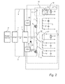
- Figure 1 illustrates an audio system comprising a single ended class D amplifier 1 connected to a power supply unit (PSU) 2 fed by a power source 3.
- the power source 3 may be AC or DC, and the power supply unit may be of switch mode type or a simple linear PSU.
- the PSU 2 has two supply rail outputs, a positive rail 4 and a negative rail 5, which are connected to and provide power to the single ended class D amplifier 1.
- the system further comprises a transformer arrangement, connected between the rails 4, 5.
- the transformer arrangement comprises a first primary winding 7 connected in series with a first switch 8 between the positive rail 4 and ground, and a second primary winding 9, connected in series with a second switch 10 between the negative rail and ground.
- the number of turns in each primary winding is preferably the same.
- the switches may be for example MOSFET transistors. The simple drive pattern of the MOSFETs enables a simple way to implement soft-switching techniques of the switches.
- the transformer arrangement further comprises one or several, in the illustrated case four, secondary windings 11, 12, 13, 14, 180 degrees phase shifted from the primary windings. These windings form an auxiliary power supply for supplying a number of housekeeping voltages for class-D amplifier operation.
- the windings 11 and 12 provide positive and negative drive voltages (typically plus or minus 5 V) for signal amplifiers (e.g. operational amplifiers) in the class D amplifier 1.
- the winding 13 provides a single voltage output intended to supply low side class-D amplifier FET-drivers. This voltage can be bootstrapped to provide a high side voltage for the FET drivers.
- the winding 14 provides an auxiliary flyback voltage. Any additional application specific flyback output voltages could be added.
- the switches 8 and 10 are controlled by a control signal Q from a controller 15, here a current mode controller.
- the control signal can be a square pulse signal, including ON-pulses separated by dead-time.
- the transformer arrangement can be implemented by a single magnetic structure.
- the transformer arrangement is a planar transformer where the windings 7, 8, 11, 12, 13, 14 are formed on a printed circuit board (PCB).
- PCB printed circuit board
- the system in figure 1 further comprises a pump current control 16, comprising a primary winding 17 connected between the first primary winding 7 and the positive rail 4, and a secondary winding 18 for detecting a magnitude of a bidirectional current through the primary winding 17.
- the pump current control 16 further comprises a feedback path 21 with a full bridge rectifier 19 and a resistor 20, which is adapted to feed a voltage across the resistor 20 back to an amplifier controller 22 connected to the single ended class D amplifier 1.
- the feedback path is here also connected to the current mode controller 15.
- the system further comprises a flyback control 23 having a first primary winding 24 connected in series with the first primary winding 7 and a second primary winding 25 connected in series with the second primary winding 9.
- the primary windings 24 and 25 are in phase.
- the flyback control 23 further comprises a secondary winding 26 coupled in phase with the primary windings 24, 25, for monitoring a magnitude of a current through the primary windings 24 and 25.
- the flyback control further comprises a feedback path 27 feeding the voltage across a resistor 28 back to the current mode controller 15.
- the primary windings 24, 25 are arranged in such a manner that the contributions from the pump currents through windings 24 and 25 cancel each other, ensuring that only the flyback current will be detected by the winding 26 and supplied to the current mode controller 15.
- the amplifier 1 is driven by the positive and negative rails 4, 5.
- the switches 8, 10 are controlled by the controller 15, to switch between a forward cycle, during which both switches 8, 10 are closed, and a flyback cycle, during which both switches are open.
- This is referred to as a supply pump reduction system, which redistributes any pumping charge from the single ended class D-amplifier by forcing current flow from the rail with the highest numerical voltage to the rail with the lowest numerical voltage.
- the pump reduction action occurs continuously cycle by cycle.
- the primary winding subject to the greatest potential difference will also charge the air gap of the transformer arrangement.
- Information about the pump current is fed back to the amplifier controller 22, and to the current mode controller 15, by the feedback path 21, for regulating the pump current and to provide over-current protection.
- the operating point and secondary output voltages of the flyback can be tailored to match any demand.
- the transformer arrangement comprises an additional clamp diode 29 connected with its anode to the drain node of the switch 10 and its cathode connected to the positive rail 4.
- additional clamp diode 29 Through this additional clamp diode 29, any energy stored in the leakage inductance of the primary windings 7 and 9 during the forward cycle will be returned to the positive rail 4 through the clamp diode 29 during the flyback cycle.
- the control signal Q controlling the switches 8, 10 preferably has a duty cycle close to 50%, which is optimum with respect to the regulation of rail imbalance due to pump cancelling.
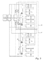
- the transformer arrangement comprises an additional set of transformer windings and switches 31, in addition to the set 30 described above.
- the additional switches 32, 33 are controlled by a control signal Q not , which is phase shifted 180 degrees with respect to Q. In other words, when Q is ON, Q neg is OFF, and vice versa.
- Q is ON, Q neg is OFF, and vice versa.
- the interleaving will enable the forward pump canceller duty cycle to be close to 100% hence obtaining almost continuous pump cancelling.
Landscapes
- Engineering & Computer Science (AREA)
- Power Engineering (AREA)
- Multimedia (AREA)
- Amplifiers (AREA)
- Dc-Dc Converters (AREA)
Priority Applications (3)
| Application Number | Priority Date | Filing Date | Title |
|---|---|---|---|
| US14/115,372 US9077257B2 (en) | 2011-05-25 | 2012-05-21 | Power supply arrangement for single ended class D amplifier |
| PCT/EP2012/059363 WO2012160021A1 (en) | 2011-05-25 | 2012-05-21 | Power supply arrangement for single ended class d amplifier |
| CN201280024234.9A CN103548249B (zh) | 2011-05-25 | 2012-05-21 | 用于单端d类放大器的供电装置 |
Applications Claiming Priority (1)
| Application Number | Priority Date | Filing Date | Title |
|---|---|---|---|
| DKPA201100397 | 2011-05-25 |
Publications (3)
| Publication Number | Publication Date |
|---|---|
| EP2533408A2 true EP2533408A2 (de) | 2012-12-12 |
| EP2533408A3 EP2533408A3 (de) | 2017-11-01 |
| EP2533408B1 EP2533408B1 (de) | 2020-01-22 |
Family
ID=45715328
Family Applications (1)
| Application Number | Title | Priority Date | Filing Date |
|---|---|---|---|
| EP11172638.6A Active EP2533408B1 (de) | 2011-05-25 | 2011-07-05 | Stromversorgungsanordnung für einen einendigen Verstärker der Klasse D |
Country Status (4)
| Country | Link |
|---|---|
| US (1) | US9077257B2 (de) |
| EP (1) | EP2533408B1 (de) |
| CN (1) | CN103548249B (de) |
| WO (1) | WO2012160021A1 (de) |
Families Citing this family (15)
| Publication number | Priority date | Publication date | Assignee | Title |
|---|---|---|---|---|
| CN103762834A (zh) * | 2013-12-31 | 2014-04-30 | 江苏嘉钰新能源技术有限公司 | 一种三相三电平vienna整流器的辅助电源 |
| TWI536727B (zh) * | 2014-05-06 | 2016-06-01 | 國立清華大學 | 脈衝電流漣波消除電路與轉換系統 |
| US9843265B2 (en) * | 2015-12-17 | 2017-12-12 | Dell Products L.P. | Zero voltage switching flyback converter |
| KR102708696B1 (ko) * | 2016-04-21 | 2024-09-24 | 삼성전자주식회사 | 전원공급장치, 이를 구비한 디스플레이 장치 및 전원 공급 방법 |
| DE102016222268A1 (de) * | 2016-11-14 | 2018-05-17 | Hochschule Reutlingen | Vorrichtung und Verfahren zur selbstverstärkenden Ansteuerung eines ladungsgesteuerten Schaltelements sowie Verwendung eines Transformators |
| JP6760051B2 (ja) * | 2016-12-27 | 2020-09-23 | Tdk株式会社 | コンバータ装置 |
| US10439414B2 (en) | 2017-03-23 | 2019-10-08 | Eaton Intelligent Power Limited | Auto adjusting balancer apparatus |
| US10381917B2 (en) * | 2017-03-23 | 2019-08-13 | Eaton Intelligent Power Limited | Power converter apparatus and methods using adaptive node balancing |
| US11958622B2 (en) | 2020-05-15 | 2024-04-16 | Pratt & Whitney Canada Corp. | Protection functions |
| US11827372B2 (en) | 2020-05-15 | 2023-11-28 | Pratt & Whitney Canada Corp. | Engine characteristics matching |
| US11794917B2 (en) | 2020-05-15 | 2023-10-24 | Pratt & Whitney Canada Corp. | Parallel control loops for hybrid electric aircraft |
| US11876445B2 (en) * | 2020-10-05 | 2024-01-16 | Infineon Technologies Austria Ag | Trans-inductance multi-phase power converters and control |
| JP7688699B2 (ja) * | 2020-11-04 | 2025-06-04 | ハーマン プロフェッショナル, インコーポレイテッド | クラスdオーディオアンプの電源レールパンピングを低減させるためのシステム及び方法 |
| US12030651B2 (en) | 2021-01-05 | 2024-07-09 | Pratt & Whitney Canada Corp. | Parallel hybrid power plant with hollow motor |
| JP7247247B2 (ja) * | 2021-03-11 | 2023-03-28 | 株式会社京三製作所 | 電力変換装置 |
Citations (1)
| Publication number | Priority date | Publication date | Assignee | Title |
|---|---|---|---|---|
| US20090102295A1 (en) | 2006-02-24 | 2009-04-23 | Lars Petersen | Audio Power Conversion System |
Family Cites Families (11)
| Publication number | Priority date | Publication date | Assignee | Title |
|---|---|---|---|---|
| FI19992660A7 (fi) * | 1999-12-10 | 2001-06-11 | Abb Industry Oy | Kondensaattoreiden jännitteenjaon tasauskytkentä |
| US6300829B1 (en) * | 2000-01-21 | 2001-10-09 | Harris Corporation | RF power amplifier system having inductive steering |
| CN1126236C (zh) * | 2001-08-24 | 2003-10-29 | 艾默生网络能源有限公司 | 一种用于电源变换器的均压电路 |
| US6639815B1 (en) * | 2002-05-04 | 2003-10-28 | Jeff Gucyski | Precision switching power amplifier comprising instantaneously interruptible power source |
| WO2005091497A1 (en) * | 2004-03-12 | 2005-09-29 | Koninklijke Philips Electronics N.V. | Switch mode power supply with output voltage equalizer |
| JP4735826B2 (ja) * | 2005-10-05 | 2011-07-27 | サンケン電気株式会社 | 電力変換装置 |
| US7961482B2 (en) * | 2007-05-09 | 2011-06-14 | International Rectifier Corporation | Bi-directional HEMT/GaN half-bridge circuit |
| US8018279B2 (en) * | 2007-06-01 | 2011-09-13 | International Rectifier Corporation | Class D amplifier circuit with bi-directional power switch |
| US8140035B2 (en) * | 2008-05-21 | 2012-03-20 | Nautel Limited | Amplifier providing power recovery from a narrow-band antenna |
| WO2010022220A1 (en) | 2008-08-22 | 2010-02-25 | Abb Inc. | Stacked flyback converter with independent current loop control |
| CN201490910U (zh) * | 2009-09-09 | 2010-05-26 | 瑞谷科技(深圳)有限公司 | 并联钳位反激电路 |
-
2011
- 2011-07-05 EP EP11172638.6A patent/EP2533408B1/de active Active
-
2012
- 2012-05-21 US US14/115,372 patent/US9077257B2/en active Active
- 2012-05-21 CN CN201280024234.9A patent/CN103548249B/zh not_active Expired - Fee Related
- 2012-05-21 WO PCT/EP2012/059363 patent/WO2012160021A1/en not_active Ceased
Patent Citations (1)
| Publication number | Priority date | Publication date | Assignee | Title |
|---|---|---|---|---|
| US20090102295A1 (en) | 2006-02-24 | 2009-04-23 | Lars Petersen | Audio Power Conversion System |
Also Published As
| Publication number | Publication date |
|---|---|
| CN103548249B (zh) | 2017-05-10 |
| EP2533408B1 (de) | 2020-01-22 |
| CN103548249A (zh) | 2014-01-29 |
| WO2012160021A1 (en) | 2012-11-29 |
| EP2533408A3 (de) | 2017-11-01 |
| US9077257B2 (en) | 2015-07-07 |
| US20140070885A1 (en) | 2014-03-13 |
Similar Documents
| Publication | Publication Date | Title |
|---|---|---|
| EP2533408B1 (de) | Stromversorgungsanordnung für einen einendigen Verstärker der Klasse D | |
| US8149597B2 (en) | Intermediate bus architecture with a quasi-regulated bus converter | |
| US6058026A (en) | Multiple output converter having a single transformer winding and independent output regulation | |
| JP4844674B2 (ja) | スイッチング電源装置 | |
| EP3282571B1 (de) | Leistungswandler mit verlängerter pufferzeit | |
| US9444246B2 (en) | Power converter with switching element | |
| US6344768B1 (en) | Full-bridge DC-to-DC converter having an unipolar gate drive | |
| EP1459431A1 (de) | Sperrleistungswandler | |
| JP4632023B2 (ja) | 電力変換装置 | |
| US8300437B2 (en) | Multi-output DC-to-DC conversion apparatus with voltage-stabilizing function | |
| US9160238B2 (en) | Power converter with current feedback loop | |
| CN101120501B (zh) | Ac/dc变换器 | |
| US8711588B1 (en) | Power supply device | |
| JP2010124567A (ja) | スイッチング電源装置 | |
| JP2000152615A (ja) | 循環コンデンサを使用する電源およびその操作方法 | |
| JP7612055B2 (ja) | 電源回路 | |
| CN102067426B (zh) | 绝缘型开关电源装置 | |
| KR101813778B1 (ko) | 하이브리드 방식 led 전원장치 | |
| Jung et al. | Novel techniques of the reduction of standby power consumption for multiple output converters | |
| JP2006158137A (ja) | スイッチング電源装置 | |
| TW202034599A (zh) | 直流脈衝電源裝置 | |
| Jung et al. | Low standby power consumption and high cross regulation of active clamp flyback converter with SSPR | |
| JP7603793B2 (ja) | スイッチング電源装置および電力供給システム | |
| JP2004166420A (ja) | 多出力スイッチング電源装置 | |
| GB2436176A (en) | Power converter with a buck power factor correction stage |
Legal Events
| Date | Code | Title | Description |
|---|---|---|---|
| PUAI | Public reference made under article 153(3) epc to a published international application that has entered the european phase |
Free format text: ORIGINAL CODE: 0009012 |
|
| AK | Designated contracting states |
Kind code of ref document: A2 Designated state(s): AL AT BE BG CH CY CZ DE DK EE ES FI FR GB GR HR HU IE IS IT LI LT LU LV MC MK MT NL NO PL PT RO RS SE SI SK SM TR |
|
| AX | Request for extension of the european patent |
Extension state: BA ME |
|
| RAP1 | Party data changed (applicant data changed or rights of an application transferred) |
Owner name: ICEPOWER A/S |
|
| REG | Reference to a national code |
Ref country code: DE Ref legal event code: R079 Ref document number: 602011064705 Country of ref document: DE Free format text: PREVIOUS MAIN CLASS: H02M0003335000 Ipc: H02M0003337000 |
|
| PUAL | Search report despatched |
Free format text: ORIGINAL CODE: 0009013 |
|
| AK | Designated contracting states |
Kind code of ref document: A3 Designated state(s): AL AT BE BG CH CY CZ DE DK EE ES FI FR GB GR HR HU IE IS IT LI LT LU LV MC MK MT NL NO PL PT RO RS SE SI SK SM TR |
|
| AX | Request for extension of the european patent |
Extension state: BA ME |
|
| RIC1 | Information provided on ipc code assigned before grant |
Ipc: H02M 3/337 20060101AFI20170927BHEP Ipc: H03F 3/217 20060101ALI20170927BHEP |
|
| STAA | Information on the status of an ep patent application or granted ep patent |
Free format text: STATUS: REQUEST FOR EXAMINATION WAS MADE |
|
| 17P | Request for examination filed |
Effective date: 20180502 |
|
| RBV | Designated contracting states (corrected) |
Designated state(s): AL AT BE BG CH CY CZ DE DK EE ES FI FR GB GR HR HU IE IS IT LI LT LU LV MC MK MT NL NO PL PT RO RS SE SI SK SM TR |
|
| GRAP | Despatch of communication of intention to grant a patent |
Free format text: ORIGINAL CODE: EPIDOSNIGR1 |
|
| STAA | Information on the status of an ep patent application or granted ep patent |
Free format text: STATUS: GRANT OF PATENT IS INTENDED |
|
| INTG | Intention to grant announced |
Effective date: 20190925 |
|
| GRAS | Grant fee paid |
Free format text: ORIGINAL CODE: EPIDOSNIGR3 |
|
| GRAA | (expected) grant |
Free format text: ORIGINAL CODE: 0009210 |
|
| STAA | Information on the status of an ep patent application or granted ep patent |
Free format text: STATUS: THE PATENT HAS BEEN GRANTED |
|
| AK | Designated contracting states |
Kind code of ref document: B1 Designated state(s): AL AT BE BG CH CY CZ DE DK EE ES FI FR GB GR HR HU IE IS IT LI LT LU LV MC MK MT NL NO PL PT RO RS SE SI SK SM TR |
|
| REG | Reference to a national code |
Ref country code: GB Ref legal event code: FG4D |
|
| REG | Reference to a national code |
Ref country code: CH Ref legal event code: EP |
|
| REG | Reference to a national code |
Ref country code: AT Ref legal event code: REF Ref document number: 1227587 Country of ref document: AT Kind code of ref document: T Effective date: 20200215 |
|
| REG | Reference to a national code |
Ref country code: IE Ref legal event code: FG4D |
|
| REG | Reference to a national code |
Ref country code: DE Ref legal event code: R096 Ref document number: 602011064705 Country of ref document: DE |
|
| REG | Reference to a national code |
Ref country code: NL Ref legal event code: MP Effective date: 20200122 |
|
| REG | Reference to a national code |
Ref country code: LT Ref legal event code: MG4D |
|
| PG25 | Lapsed in a contracting state [announced via postgrant information from national office to epo] |
Ref country code: PT Free format text: LAPSE BECAUSE OF FAILURE TO SUBMIT A TRANSLATION OF THE DESCRIPTION OR TO PAY THE FEE WITHIN THE PRESCRIBED TIME-LIMIT Effective date: 20200614 Ref country code: NL Free format text: LAPSE BECAUSE OF FAILURE TO SUBMIT A TRANSLATION OF THE DESCRIPTION OR TO PAY THE FEE WITHIN THE PRESCRIBED TIME-LIMIT Effective date: 20200122 Ref country code: RS Free format text: LAPSE BECAUSE OF FAILURE TO SUBMIT A TRANSLATION OF THE DESCRIPTION OR TO PAY THE FEE WITHIN THE PRESCRIBED TIME-LIMIT Effective date: 20200122 Ref country code: NO Free format text: LAPSE BECAUSE OF FAILURE TO SUBMIT A TRANSLATION OF THE DESCRIPTION OR TO PAY THE FEE WITHIN THE PRESCRIBED TIME-LIMIT Effective date: 20200422 Ref country code: FI Free format text: LAPSE BECAUSE OF FAILURE TO SUBMIT A TRANSLATION OF THE DESCRIPTION OR TO PAY THE FEE WITHIN THE PRESCRIBED TIME-LIMIT Effective date: 20200122 |
|
| PG25 | Lapsed in a contracting state [announced via postgrant information from national office to epo] |
Ref country code: BG Free format text: LAPSE BECAUSE OF FAILURE TO SUBMIT A TRANSLATION OF THE DESCRIPTION OR TO PAY THE FEE WITHIN THE PRESCRIBED TIME-LIMIT Effective date: 20200422 Ref country code: IS Free format text: LAPSE BECAUSE OF FAILURE TO SUBMIT A TRANSLATION OF THE DESCRIPTION OR TO PAY THE FEE WITHIN THE PRESCRIBED TIME-LIMIT Effective date: 20200522 Ref country code: GR Free format text: LAPSE BECAUSE OF FAILURE TO SUBMIT A TRANSLATION OF THE DESCRIPTION OR TO PAY THE FEE WITHIN THE PRESCRIBED TIME-LIMIT Effective date: 20200423 Ref country code: SE Free format text: LAPSE BECAUSE OF FAILURE TO SUBMIT A TRANSLATION OF THE DESCRIPTION OR TO PAY THE FEE WITHIN THE PRESCRIBED TIME-LIMIT Effective date: 20200122 Ref country code: LV Free format text: LAPSE BECAUSE OF FAILURE TO SUBMIT A TRANSLATION OF THE DESCRIPTION OR TO PAY THE FEE WITHIN THE PRESCRIBED TIME-LIMIT Effective date: 20200122 Ref country code: HR Free format text: LAPSE BECAUSE OF FAILURE TO SUBMIT A TRANSLATION OF THE DESCRIPTION OR TO PAY THE FEE WITHIN THE PRESCRIBED TIME-LIMIT Effective date: 20200122 |
|
| REG | Reference to a national code |
Ref country code: DE Ref legal event code: R097 Ref document number: 602011064705 Country of ref document: DE |
|
| PG25 | Lapsed in a contracting state [announced via postgrant information from national office to epo] |
Ref country code: ES Free format text: LAPSE BECAUSE OF FAILURE TO SUBMIT A TRANSLATION OF THE DESCRIPTION OR TO PAY THE FEE WITHIN THE PRESCRIBED TIME-LIMIT Effective date: 20200122 Ref country code: CZ Free format text: LAPSE BECAUSE OF FAILURE TO SUBMIT A TRANSLATION OF THE DESCRIPTION OR TO PAY THE FEE WITHIN THE PRESCRIBED TIME-LIMIT Effective date: 20200122 Ref country code: DK Free format text: LAPSE BECAUSE OF FAILURE TO SUBMIT A TRANSLATION OF THE DESCRIPTION OR TO PAY THE FEE WITHIN THE PRESCRIBED TIME-LIMIT Effective date: 20200122 Ref country code: SM Free format text: LAPSE BECAUSE OF FAILURE TO SUBMIT A TRANSLATION OF THE DESCRIPTION OR TO PAY THE FEE WITHIN THE PRESCRIBED TIME-LIMIT Effective date: 20200122 Ref country code: EE Free format text: LAPSE BECAUSE OF FAILURE TO SUBMIT A TRANSLATION OF THE DESCRIPTION OR TO PAY THE FEE WITHIN THE PRESCRIBED TIME-LIMIT Effective date: 20200122 Ref country code: SK Free format text: LAPSE BECAUSE OF FAILURE TO SUBMIT A TRANSLATION OF THE DESCRIPTION OR TO PAY THE FEE WITHIN THE PRESCRIBED TIME-LIMIT Effective date: 20200122 Ref country code: RO Free format text: LAPSE BECAUSE OF FAILURE TO SUBMIT A TRANSLATION OF THE DESCRIPTION OR TO PAY THE FEE WITHIN THE PRESCRIBED TIME-LIMIT Effective date: 20200122 Ref country code: LT Free format text: LAPSE BECAUSE OF FAILURE TO SUBMIT A TRANSLATION OF THE DESCRIPTION OR TO PAY THE FEE WITHIN THE PRESCRIBED TIME-LIMIT Effective date: 20200122 |
|
| REG | Reference to a national code |
Ref country code: AT Ref legal event code: MK05 Ref document number: 1227587 Country of ref document: AT Kind code of ref document: T Effective date: 20200122 |
|
| PLBE | No opposition filed within time limit |
Free format text: ORIGINAL CODE: 0009261 |
|
| STAA | Information on the status of an ep patent application or granted ep patent |
Free format text: STATUS: NO OPPOSITION FILED WITHIN TIME LIMIT |
|
| 26N | No opposition filed |
Effective date: 20201023 |
|
| PG25 | Lapsed in a contracting state [announced via postgrant information from national office to epo] |
Ref country code: IT Free format text: LAPSE BECAUSE OF FAILURE TO SUBMIT A TRANSLATION OF THE DESCRIPTION OR TO PAY THE FEE WITHIN THE PRESCRIBED TIME-LIMIT Effective date: 20200122 Ref country code: AT Free format text: LAPSE BECAUSE OF FAILURE TO SUBMIT A TRANSLATION OF THE DESCRIPTION OR TO PAY THE FEE WITHIN THE PRESCRIBED TIME-LIMIT Effective date: 20200122 |
|
| PG25 | Lapsed in a contracting state [announced via postgrant information from national office to epo] |
Ref country code: PL Free format text: LAPSE BECAUSE OF FAILURE TO SUBMIT A TRANSLATION OF THE DESCRIPTION OR TO PAY THE FEE WITHIN THE PRESCRIBED TIME-LIMIT Effective date: 20200122 Ref country code: MC Free format text: LAPSE BECAUSE OF FAILURE TO SUBMIT A TRANSLATION OF THE DESCRIPTION OR TO PAY THE FEE WITHIN THE PRESCRIBED TIME-LIMIT Effective date: 20200122 Ref country code: SI Free format text: LAPSE BECAUSE OF FAILURE TO SUBMIT A TRANSLATION OF THE DESCRIPTION OR TO PAY THE FEE WITHIN THE PRESCRIBED TIME-LIMIT Effective date: 20200122 |
|
| REG | Reference to a national code |
Ref country code: CH Ref legal event code: PL |
|
| REG | Reference to a national code |
Ref country code: BE Ref legal event code: MM Effective date: 20200731 |
|
| PG25 | Lapsed in a contracting state [announced via postgrant information from national office to epo] |
Ref country code: CH Free format text: LAPSE BECAUSE OF NON-PAYMENT OF DUE FEES Effective date: 20200731 Ref country code: LI Free format text: LAPSE BECAUSE OF NON-PAYMENT OF DUE FEES Effective date: 20200731 Ref country code: IE Free format text: LAPSE BECAUSE OF NON-PAYMENT OF DUE FEES Effective date: 20200705 Ref country code: LU Free format text: LAPSE BECAUSE OF NON-PAYMENT OF DUE FEES Effective date: 20200705 |
|
| PG25 | Lapsed in a contracting state [announced via postgrant information from national office to epo] |
Ref country code: BE Free format text: LAPSE BECAUSE OF NON-PAYMENT OF DUE FEES Effective date: 20200731 |
|
| PG25 | Lapsed in a contracting state [announced via postgrant information from national office to epo] |
Ref country code: TR Free format text: LAPSE BECAUSE OF FAILURE TO SUBMIT A TRANSLATION OF THE DESCRIPTION OR TO PAY THE FEE WITHIN THE PRESCRIBED TIME-LIMIT Effective date: 20200122 Ref country code: MT Free format text: LAPSE BECAUSE OF FAILURE TO SUBMIT A TRANSLATION OF THE DESCRIPTION OR TO PAY THE FEE WITHIN THE PRESCRIBED TIME-LIMIT Effective date: 20200122 Ref country code: CY Free format text: LAPSE BECAUSE OF FAILURE TO SUBMIT A TRANSLATION OF THE DESCRIPTION OR TO PAY THE FEE WITHIN THE PRESCRIBED TIME-LIMIT Effective date: 20200122 |
|
| PG25 | Lapsed in a contracting state [announced via postgrant information from national office to epo] |
Ref country code: MK Free format text: LAPSE BECAUSE OF FAILURE TO SUBMIT A TRANSLATION OF THE DESCRIPTION OR TO PAY THE FEE WITHIN THE PRESCRIBED TIME-LIMIT Effective date: 20200122 Ref country code: AL Free format text: LAPSE BECAUSE OF FAILURE TO SUBMIT A TRANSLATION OF THE DESCRIPTION OR TO PAY THE FEE WITHIN THE PRESCRIBED TIME-LIMIT Effective date: 20200122 |
|
| P01 | Opt-out of the competence of the unified patent court (upc) registered |
Effective date: 20230523 |
|
| PGFP | Annual fee paid to national office [announced via postgrant information from national office to epo] |
Ref country code: GB Payment date: 20250604 Year of fee payment: 15 |
|
| PGFP | Annual fee paid to national office [announced via postgrant information from national office to epo] |
Ref country code: FR Payment date: 20250603 Year of fee payment: 15 |
|
| PGFP | Annual fee paid to national office [announced via postgrant information from national office to epo] |
Ref country code: DE Payment date: 20250603 Year of fee payment: 15 |