EP2533423B1 - Verfahren zur zeitlich hochgenauen Detektion eines grenzwertüberschreitenden Moments durch ein Signal - Google Patents
Verfahren zur zeitlich hochgenauen Detektion eines grenzwertüberschreitenden Moments durch ein Signal Download PDFInfo
- Publication number
- EP2533423B1 EP2533423B1 EP11425151.5A EP11425151A EP2533423B1 EP 2533423 B1 EP2533423 B1 EP 2533423B1 EP 11425151 A EP11425151 A EP 11425151A EP 2533423 B1 EP2533423 B1 EP 2533423B1
- Authority
- EP
- European Patent Office
- Prior art keywords
- signal
- comparison
- instant
- module
- amplitude
- Prior art date
- Legal status (The legal status is an assumption and is not a legal conclusion. Google has not performed a legal analysis and makes no representation as to the accuracy of the status listed.)
- Active
Links
- 238000000034 method Methods 0.000 title claims description 51
- 230000002123 temporal effect Effects 0.000 title claims description 22
- 238000001514 detection method Methods 0.000 claims description 129
- 238000005070 sampling Methods 0.000 claims description 53
- 238000004364 calculation method Methods 0.000 claims description 32
- 238000012360 testing method Methods 0.000 claims description 22
- 230000004913 activation Effects 0.000 claims description 20
- 230000000875 corresponding effect Effects 0.000 claims description 20
- 238000006243 chemical reaction Methods 0.000 claims description 17
- 230000007274 generation of a signal involved in cell-cell signaling Effects 0.000 claims description 16
- 230000001360 synchronised effect Effects 0.000 claims description 10
- 230000003111 delayed effect Effects 0.000 claims description 9
- 230000002596 correlated effect Effects 0.000 claims description 5
- 230000004044 response Effects 0.000 claims description 5
- 230000000630 rising effect Effects 0.000 claims description 5
- 238000012545 processing Methods 0.000 description 8
- 230000005540 biological transmission Effects 0.000 description 5
- 238000010586 diagram Methods 0.000 description 5
- 230000006870 function Effects 0.000 description 4
- 239000003990 capacitor Substances 0.000 description 3
- 230000008859 change Effects 0.000 description 2
- 230000001419 dependent effect Effects 0.000 description 2
- 230000004807 localization Effects 0.000 description 2
- 238000005192 partition Methods 0.000 description 2
- 230000008054 signal transmission Effects 0.000 description 2
- 108010076504 Protein Sorting Signals Proteins 0.000 description 1
- 238000013459 approach Methods 0.000 description 1
- 230000003247 decreasing effect Effects 0.000 description 1
- 230000001934 delay Effects 0.000 description 1
- 238000013461 design Methods 0.000 description 1
- 230000006866 deterioration Effects 0.000 description 1
- 238000005265 energy consumption Methods 0.000 description 1
- 230000006872 improvement Effects 0.000 description 1
- 230000008569 process Effects 0.000 description 1
- 230000009466 transformation Effects 0.000 description 1
- 230000001131 transforming effect Effects 0.000 description 1
Images


Classifications
-
- H—ELECTRICITY
- H04—ELECTRIC COMMUNICATION TECHNIQUE
- H04B—TRANSMISSION
- H04B17/00—Monitoring; Testing
- H04B17/10—Monitoring; Testing of transmitters
- H04B17/15—Performance testing
- H04B17/17—Detection of non-compliance or faulty performance, e.g. response deviations
-
- H—ELECTRICITY
- H03—ELECTRONIC CIRCUITRY
- H03K—PULSE TECHNIQUE
- H03K5/00—Manipulating of pulses not covered by one of the other main groups of this subclass
- H03K5/01—Shaping pulses
- H03K5/08—Shaping pulses by limiting; by thresholding; by slicing, i.e. combined limiting and thresholding
-
- H—ELECTRICITY
- H03—ELECTRONIC CIRCUITRY
- H03K—PULSE TECHNIQUE
- H03K5/00—Manipulating of pulses not covered by one of the other main groups of this subclass
- H03K5/153—Arrangements in which a pulse is delivered at the instant when a predetermined characteristic of an input signal is present or at a fixed time interval after this instant
- H03K5/1534—Transition or edge detectors
Definitions
- the present invention relates to the detection of a threshold crossing instant by an electrical signal, by means of an electronic device.
- the invention relates to a method and a device capable of detecting, with a high temporal accuracy, a threshold crossing instant of an electrical signal converted in digital form.
- the threshold crossing may be representative, in different application scopes, of different events: for example, it may be associated to a change in the digital logical level, or it may discriminate a condition of signal "absence” (off) from a condition of signal "presence” (on), or vice versa.
- the crossing instant of a threshold may represent a "time of arrival” (TOA) or a “time of transmission” (TOT) of the signal.
- TOA time of arrival
- TOT time of transmission
- TOA and TOT are well known in the considered technical field, especially in the context of systems for which the time of arrival or transmission of a signal is essential: this is true, for example, in reception and transmission systems for radar signals, or in localization (such as the GPS system) or synchronization systems.
- the detection in such systems it is essential for the detection to be temporally accurate, that is, it should occur in an instant having a fixed delay, known with a high accuracy and steady, relative to the instant at which the signal is physically received, for example by an analogue receiver.
- the requirements of a system for detecting the time of arrival relate not much to the instantaneity of the detection but to the temporal accuracy thereof.
- the time of arrival of a signal may be defined as the instant at which the leading edge thereof crosses a threshold depending on the maximum amplitude of the signal itself, where the threshold may be defined in linear scale or in logarithmic scale.
- a level is chosen as a threshold whereat the time derivative of the signal is high, or even maximum, in order to facilitate the detection.
- threshold level a level corresponding to 50% of the maximum signal amplitude, in linear notation, which in logarithmic notation corresponds to a level set at -6dB relative to the maximum peak reached.
- the threshold crossing in this case a sort of signal recording is required, in analogue or digital form, which allows evaluating the amplitude thereof, and thus calculating the threshold (in this example corresponding to 50% of the amplitude), determining the instant at which the signal crosses such threshold and emitting a detection signal of a time of arrival, having a fixed and known delay relative to the time of arrival.
- a known method for determining the time of arrival of the signal consists in detecting the signal peak (that is, the maximum amplitude reached), dividing such peak by two (that is, attenuating it by 6 dB) for generating a constant halved peak signal, and comparing such constant halved peak signal with the original signal delayed by a delay T0, at least equal to the time taken by the signal for rising from 50% to 100% of its peak level.
- the first crossing between the halved peak signal and the original delayed signal takes place at 50% (that is, at -6 dB) of the peak level of the original delayed signal.
- a detection signal, or “trigger” of the time of arrival is generated at the instant at which such crossing takes place, trigger which is synchronised with the time of arrival, with a delay equal to delay T0 imposed to the signal.
- the method described above may be implemented by analogue electronics. In this case, however, the detection accuracy of the time of arrival is related to noise and thermal drift features of the analogue circuits that are used.
- the analogue detection method is less and less least used, because of the accuracy limitations due to the reasons mentioned above. Moreover, the analogue nature of such method does not allow having numerical results and outcomes and therefore it cannot be used in the field of digital electronics, nowadays prevailing.
- the state of the art envisages that the same functional method for determining the time of arrival, described above, is converted in a mathematical algorithm implementable through a digital circuitry, which in particular may be an FPGA (Field Programmable Gate Array) circuitry.
- a digital circuitry which in particular may be an FPGA (Field Programmable Gate Array) circuitry.
- the input signal is acquired with an analogue-digital converter (ADC), and all the following process is performed through numerical calculations.
- ADC analogue-digital converter
- the use of clocks with cost and complexity compatible with the scope considered limits the temporal resolution of the detection of the threshold crossing instant: the order of magnitude of such resolution is comparable to the clock period.
- the detection error margin, comparable to the clock period may be unsatisfactory for many applications, such as the already mentioned reception and transmission systems for radars or for GPS localizers.
- the object of the present invention is to devise and provide a method and a device for detecting a threshold crossing instant by an electrical signal, improved in such a way as to obviate at least partly to the drawbacks mentioned above with reference to the prior art.
- a method for detecting a threshold crossing instant which exhibits a high temporal accuracy, such as to make the temporal detection error much lower than the clock period of the clock of the device that implements said method.
- a method for asserting a trigger, with fast edge compared to the edge of an electrical signal, having a known delay and such an accuracy as to make it indicative of the threshold crossing instant, by the electrical signal, with an expected resolution.
- An electronic detection device configured for implementing the method according to the invention is defined in claim 12.
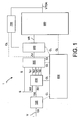
- an electronic device 1 for detecting a threshold crossing instant TOA, at which an electrical signal V crosses a threshold S, is described, according to an example of the present invention.
- the detection device 1 comprises an analogue to digital conversion module 100 having an input 101 and an output 102 of conversion module.
- the conversion module 100 is configured for sampling the electrical signal V, provided to input 101, with a sampling period T, and for providing a sequence of sampled signal values Vn to output 102.
- sampling is performed at sampling instants Ts, temporally equally spaced from one another by a sampling period T, which belong to a more general sequence of clock instants Tn, defined by a clock signal CL having clock period T equal to the sampling period T.
- the sequence of sampled signal values Vn comprises a sampled signal value Vn in each one of the sampling instants Ts.
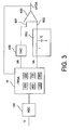
- the conversion module 100 may consist, for example, of an analogue-digital converter (ADC), per se known, as shown in figure 3 .
- ADC analogue-digital converter
- the clock signal CL is generated by a synchronization unit 800, comprised in the detection device 1.
- the synchronization unit 800 is configured for generating a clock signal CL having a clock period T equal to the sampling period T, so as to define the sequence of clock instants Tn; moreover, the synchronization unit is operatively connected to the conversion module 100 and to further modules of the device 1 that will be described hereinafter (for example, detection module 200, calculation module 300, setting module 400 and comparison module 500), for providing the clock signal CL.
- the detection device 1 further comprises a detection module 200 having a first detection module input 201 operatively connected to the conversion module output 102, for receiving the sequence of sampled signal values Vn, and a second detection module input 202 for receiving a value representative of threshold S (that hereinafter will also be defined as "threshold").
- the detection module 200 is configured for detecting a first sampling instant Ts1 and a subsequent consecutive second sampling instant Ts2, such that in one of said first Ts1 and second Ts2sampling instants the sampled signal value has a first signal value V1 lower than, or equal to, threshold S, and in the other one of said first Ts1 and second sampling instants Ts1 the sampled signal value takes on a second signal value V2 higher than the threshold.
- the value V1 is the sampled signal value at instant Ts1
- the value V2 is the sampled signal value at instant Ts2; and vice versa, if signal V is decreasing.
- the detection module 200 is further configured for providing in output the first signal value V1, the second signal value V2 and the threshold S.
- the detection module 200 also specifies in output which are the first Ts1 and the second Ts2 sampling instants detected.
- the detection module 200 may consist, for example, of a digital circuit, per se known.
- FIG. 4A A temporal diagram exemplifying what illustrated above is shown in figure 4A , wherein there are shown in particular the sampled signal values Vn at the output of the detection module 200, as well as the first Ts1 and the second Ts2 sampling instants detected, and the respective first signal value V1 and second signal value V2.
- Figure 4A also shows the threshold crossing instant TOA, which is to be detected, which lies necessarily between said first Ts1 and second Ts2 sampling instant.
- device 1 further comprises a time interval calculation module 300 , which is operatively connected to the detection module 200 for receiving the first signal value V1, the second signal value V2 and the threshold S.
- the calculation module 300 is configured for calculating and providing in output, on the basis of the first signal value V1, the second signal value V2 and the threshold S, a value of a first time interval At, indicative of a temporal distance between the threshold crossing instant TOA and the first sampling instant Ts1.
- the calculation module 300 may consist, for example, of a logical digital circuit, per se known, or it may be implemented by a processor present in device 1.
- the first time interval At is fractional with respect to the sampling period T since, as already noted, the threshold crossing instant TOA lies between the first and the second sampling instants. For this reason, such first time interval is calculated by the device 1 and is not directly detected.
- the threshold crossing instant TOA would be approximated to the first Ts1 or to the second Ts2 sampling instant detected.
- the identification of the fractional interval At is aimed at a more accurate detection, as will be further illustrated hereinafter.
- At it may be performed on the basis of a linear interpolation, according to an exemplary embodiment.
- the first time interval At is calculated as proportional to the ratio between the difference between the threshold value S and the first signal value V1, and the difference between the second signal value V2 and the first signal value V1.
- the calculation module 300 is configured for performing the above calculations in linear scale or in logarithmic scale.
- the detection device 1 then comprises a reference amplitude setting module 400, operatively connected to the calculation module 300 for receiving the calculated value of the first time interval At, and also configured for setting a reference electrical signal VR (hereinafter also defined as “reference signal VR”), having a reference amplitude VR representative of the first time interval value At, relative to a reference scale.
- a reference electrical signal VR hereinafter also defined as "reference signal VR”
- the setting module 400 therefore has the twofold function of transforming a first time interval value At into a respective reference amplitude value VR, in biunique correspondence with one another; and thus of generating a reference electrical signal having an amplitude equal to the reference amplitude VR.
- Such reference electrical signal in the embodiments described herein, is preferably a voltage; in further embodiments, it may be another type of signal, for example a current.
- the setting module 400 therefore comprises a logical digital circuit for the processing required for the transformation from At to VR; and a voltage generator, per se known as well, driven by said processing circuit for generating a reference electrical signal with amplitude equal to VR.
- the detection device 1 further comprises a comparison module 500, operatively connected to the setting module 400 for receiving the reference signal VR.
- the comparison module 500 is configured for generating a threshold crossing detection signal VTOA, at a threshold crossing detection instant TTOA (hereinafter also defined as "detection instant TTOA"), so that the detection instant TTOA depends on the reference amplitude VR, that is, on the amplitude of the reference electrical signal VR that is received in input.
- detection instant TTOA a threshold crossing detection instant TTOA
- the relation between a reference amplitude VR and the respective detection instant is known and is characteristic of the comparison module 500, so that the detection instant TTOA is delayed by a second time interval At' relative to a reference instant Tr belonging to the sequence of clock instants Tn.
- the comparison module 500 may consist, for example, of analogue or digital circuits, or of combinations of analogue and digital circuits. A preferred embodiment of the comparison module 500 will be illustrated hereinafter, while describing figure 2 .
- the reference instant Tr depends on the processing times and on the delays introduced by the elements of the processing chain of the detection device 1 (for example, the elements shown in figure 1 ).
- the delay of such reference instant Tr relative to the first sampling instant Ts1 is therefore known, once the structure of the device 1 has been defined.
- the temporal distance between Tr and the first sampling instant Ts1 is a multiple of the clock period T, thanks to the fact that instant Tr belongs to sequence Tn of clock signals, which dictates the operation of the entire system.
- the threshold crossing detection instant TTOA is not bound to belong to the sequence Tn, and usually it is not.
- this aspect allows to release from the resolution imposed by the clock period and advantageously, to improve the temporal accuracy of the detection.
- the second time interval At' that is, the delay of instant TTOA relative to instant Tr, is fractional relative to the clock period T.
- the detection device further comprises a calibration module 700, operatively connected to the setting module 400 on one side, and to the comparison module 500 on the other.
- the calibration module 700 is configured for calibrating the reference scale of the reference amplitude VR so that the second time interval At' is substantially equal to the first time interval At.
- said calibration may be performed by an operating test of the setting module 400 and of the comparison module 500; or by means of calculations based on relations that are predefined on the basis of the actual implementation of said modules; or on a combination of said two approaches.
- the calibration module 700 may be implemented, for example, by means of a logical digital circuitry.
- the calibration module 700 allows to ensure that the threshold crossing detection instant TTOA is synchronous with respect to the threshold crossing instant TOA, with a known and fixed delay.
- Tr - Ts1 that is, the delay between Tr and Ts1
- Tr the delay between Tr and Ts1
- the extent of the delay elapsing between the instant at which the threshold crossing TTOA is detected and instant TOA at which the threshold has been crossed is not a problem for a detection device, provided that such delay is known and fixed, as ensured by the device according to the invention.
- the threshold crossing detection signal VTOA is therefore a valid indicator of the threshold crossing by signal V, since it is synchronous with the threshold crossing instant, with a known and fixed delay.
- a detection signal of a crossing instant may change status only upon the occurrence of clock instants Tn of the system, and therefore the accuracy thereof is limited by such discretization granularity.
- the generation of the detection signal VTOA is not bound to an instant of the sequence of clock signals Tn, but can occur in any instant, and is therefore capable of detecting the threshold crossing instant with a higher accuracy than the clock period of the device.
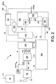
- the comparison module 500 comprises a comparison signal generation circuit 550, having an input 551 provided for receiving an electrical activation signal VA at an activation instant Ta.
- the comparison signal generation circuit 550 is configured for generating, in response to the electrical activation signal VA, an electrical comparison signal VC, having a substantially linear evolution over time, starting from a comparison start instant Tc and during a comparison period ⁇ TC longer than the clock period T, so as to cover a comparison signal range ⁇ VC in a time period equal to the clock period T.
- comparison signal range ⁇ VC must be correlated in a known manner to the reference scale of the reference amplitude VR, as will be described hereinafter.
- the comparison module 500 further comprises a comparator circuit 600 having a first comparator circuit input 601 operatively connected to the comparison signal generation circuit 550 for receiving the comparison signal VC, and a second comparator circuit input 602 operatively connected to the setting module 400 for receiving the reference signal VR.
- the comparator circuit 600 is configured for providing a comparator output signal VTOA at a comparator output signal instant TTOA, which is synchronous, with a nominally fixed delay, relative to a crossing instant Ti at which the comparison signal VC reaches an amplitude equal to the reference electrical signal VR.
- the setting module 400 provides a reference amplitude in digital format.
- the comparison module 500 further comprises a digital to analogue conversion module 450, configured for converting the reference amplitude in digital format into a reference amplitude in analogue format.
- the digital to analogue conversion module 450 is operatively connected to the setting module 400, for receiving the reference amplitude VR in digital format, and to the second input of the comparator circuit 600, for providing the reference amplitude in analogue format.
- the comparator output signal VTOA is just the threshold crossing detection signal VTOA
- the comparator output signal instant TTOA is the detection instant TTOA.
- the detection signal VTOA is emitted with a known nominal delay, typical of the comparator circuit, relative to said crossing instant between the comparison signal VC and the reference signal VR.
- the comparison signal generator circuit 550 in an embodiment shown in figure 3 , is an analogue circuit 550 comprising a resistor r and a capacitor c and having a time constant rc longer than the sampling period T.
- the activation signal VA is typically a step voltage signal that has the goal of charging the capacitor c.
- the charging of capacitor c, over time, at the output of the analogue circuit 550, generates a voltage signal having for a first portion an almost linear evolution , which may serve as comparison signal VC.
- the synchronization unit 800 is further configured for generating the activation signal VA in the activation instant Ta, and further operatively connected to input 551 of the comparison signal generator circuit 550 for providing such activation signal VA.
- the activation signal VA, resistor r, capacity c, and thus the time constant rc of the analogue circuit 550 are sized according to well known criteria, so as to obtain an almost linear rising of the comparison signal VC, for a period longer than the clock period T.
- the comparison period ⁇ TC is longer than the clock period T and advantageously, is longer than two clock periods.
- the comparison signal VC rises linearly, in the comparison period ⁇ TC, from a minimum comparison signal value VCmin, taken at the comparison start instant Tc, to a maximum comparison signal value VCmax, taken at instant Tc + ⁇ TC, at the end of the comparison period.
- the calibration module 700 and the setting module 400 cooperate so as to define the reference scale of the reference amplitude VR as a linear scale, on the basis of a reference amplitude range ⁇ VR between a minimum reference amplitude VRmin and a maximum reference amplitude VRmax, so that the following conditions occur: the crossing between the comparison signal VC and the minimum reference amplitude VRmin occurs at an instant TRmin comprised within the comparison period ⁇ TC; the crossing between the comparison signal VC and the maximum reference amplitude VRmax occurs at an instant TRmax comprised within the comparison period ⁇ TC; the reference amplitude range ⁇ VR is equal to the comparison signal range ⁇ VC, so that the length of the time interval between TRmin and TRmax is equal to a sampling period T; for each reference amplitude value VR comprised between said values VRmin and VRmax, the crossing between the comparison signal VC and said amplitude VR occurs at a crossing instant Ti, comprised between said instants TRmin and TRmax.
- the minimum reference amplitude VRmin is equal to, or higher than, the minimum comparison signal value VCmin; the maximum reference amplitude VRmax is equal to, or lower than, a maximum comparison signal value VCmax.
- the crossing instant Ti at which the comparison signal VC reaches an amplitude VR, comprised between VRmin and VRmax, varies within the time period T, between instants TRmin and TRmax, in a linear manner with respect to amplitude VR.
- the reference amplitude VR is calculated, on the basis of the time interval At, so that the ratio between a reference difference, between the reference amplitude VR and the minimum reference amplitude VRmin, and the reference amplitude range ⁇ VR is substantially equal to the ratio between the first time interval At and the clock period T.
- the calculation for determining the reference amplitude VR, corresponding to the above formula (7), is performed by the calibration module 700.
- the calculation for determining the reference amplitude VR, corresponding to the above formula (7), is performed by the setting module 400.
- the detection device 1 further comprises a memory unit 900 provided for storing a correspondence table, comprising a pair of correspondence fields for each one of a plurality of time intervals At; such pair of correspondence fields comprises a first field containing a respective time interval value At and a second field containing a corresponding reference amplitude VR calculated, for example, on the basis of formula (7).
- the calibration module 700 is further configured for calculating a reference amplitude for each of the reference amplitudes VR of the correspondence table, for example by formula (7).
- the calibration module 700 is also operatively connected to the memory unit 900 for storing such calculated reference amplitudes to the correspondence table of the memory unit.
- the memory unit 900 is operatively connected to the setting module 400 for receiving a time interval value At there from and for providing, in response thereto, the corresponding reference amplitude VR, stored in the second field of the pair of correspondence fields which contains said received time interval value (At) in the first field. In this way, the setting module 400 can set the correct reference amplitude VR.
- a similar use of the memory unit 900 may of course be provided when the mathematical relation between quantities At and VR differs from formula (7), being for example a non linear relation.
- the correspondence table provides for N pairs of correspondence fields (where N may be any number, for example typically, 100) and this implies that a single clock period T contains N sub-periods that define the fine granularity with which the first time interval At can be detected.
- the accuracy with which the threshold crossing instant can be detected increases by a factor N (for example 100, that is, two orders of magnitude) relative to the clock period T.
- the detection device 1 employed for example in case the electrical signal V is a pulse or step signal, rising or descending, having a leading or trailing edge substantially monotonic, and further having a peak value Vmax; and wherein threshold S is correlated to the peak value (Vmax) by a multiplicative parameter f comprised between 0 and 1.
- a multiplicative parameter f comprisesd between 0 and 1.
- such multiplicative parameter takes a value 0.5, which corresponds to the case in which the threshold is defined as 50% of the peak value Vmax.
- the detection device 1 further comprises a reception module 50 of the electrical signal V, operatively connected to the conversion module 100, for providing the electrical signal V.
- the detection device 1 comprises a threshold calculation module 150, operatively connected to the conversion module 100 for receiving the sampled electrical signal in digital format, provided at output 102, and configured for detecting the peak value Vmax and for attenuating such peak value by the multiplicative parameter f, so as to obtain a threshold value S.
- the threshold calculation module 150 is also operatively connected to input 202 of the detection module 200 for providing the calculated threshold value S.
- the threshold calculation module 150 is further configured for introducing an initial delay T0, on the electrical signal sampled, so as to provide the threshold level S before a comparison with the sampled signal values Vn, by the detection module 200.
- the threshold calculation module 150 for example comprises a digital delay module (not shown in figure 2 ).
- the initial delay T0 may be introduced by the reception module 50, on the electrical signal V in analogue format.
- the peak value Vmax and the calculation of the threshold value S are performed by the reception module 50, on the electrical signal V in analogue format.
- the threshold calculation module 150 is not provided and the reception module 50 is operatively connected to the detection module 200, for providing the threshold value S.
- the threshold calculation module 150, the detection module 200, the calculation module 300, the setting module 400, the calibration module 700 and the memory unit 900 are comprised in a processing module 10 of the detection device 1 (shown in figure 3 ).
- the processing module 10 consists of an FPGA (Field Programmable Gate Array) digital circuitry.
- the partition of the FPGA digital circuitry may also differ from the functional partition of device 1, but generally carrying out the same functions.
- analogue parts consisting of analogue circuits: for example, these are the comparison signal generation circuit 550 and the comparator circuit 600.
- the features of such analogue parts sometimes have such tolerances as to at least partly reduce the temporal accuracy of the detection.
- some of such features depend on temperature and may slowly vary over time.
- the calibration module 700 is further configured for performing the following further calibration operations: providing a sequence of test reference electrical signals to the comparison module 500; then, determining a minimum test reference signal amplitude for which the comparison module 500 generates the threshold crossing detection signal TTOA synchronized with the reference instant Tr; then, determining a maximum test reference signal amplitude for which the comparison module 500 generates the threshold crossing detection signal VTOA with a delay equal to the clock period T relative to the reference instant Tr; finally, defining the reference scale of the reference amplitude VR on the basis of said maximum test reference signal amplitude and minimum test reference signal amplitude.
- the reference scale may be defined as a linear scale having said minimum test reference signal amplitude as minimum reference amplitude VRmin; and said maximum test reference signal amplitude as maximum reference amplitude VRmax.
- minimum VRmin and maximum VRmax reference amplitudes and thus also the reference amplitude range ⁇ VR, it is possible to calculate the relations referred to the other reference amplitudes VR, for example using formulae (6) and (7).
- the above calibration allows to move the interval of amplitudes from VRmin to VRmax, within the wider interval from VCmin to VCmax; and consequently this allows to move the time period T, between instants TRmin and TRmax, within the wider comparison time period ⁇ TC, so that the detection instant TTOA, for which At is equal to 0, remains linked to the reference instant Tr.
- the sequence of further calibration operations is carried out periodically, in different periods than the normal operating periods of the detection device 1.
- the periodicity of such sequences is shorter than the average stability time of the analogue parameters of device 1, the fluctuations whereof are to be compensated, so that such fluctuations never impair the detection accuracy.
- the calibration module 700 comprises a disabling output 705, and is configured for providing a disabling signal VDIS through such disabling output 705 to an electrical circuit, arranged downstream of device 1, which uses the detection signal VTOA.
- a disabling signal VDIS is activated during the periods in which said sequence of further calibration operations is performed, during which the detection device does not perform the standard detection operations.
- said sequence of further calibration operations mainly aims at obviating drifts of age and temperature the passive analogue components of device 1 may optionally be subject to; and moreover it allows to check that the comparison signal generation circuit 550 continues to operate in linear zone, and exhibits no excessive variations due to possible deteriorations or breakage.
- the invention comprises a method for detecting, through an electronic detection device 1, a threshold crossing instant TOA at which an electrical signal V crosses a threshold S, comprising the following steps: defining a sequence of discrete clock instants Tn by a clock signal CL, such that two consecutive clock instants of the sequence are spaced in time from one another by a clock period T; then, sampling the electrical signal V with a sampling period T equal to the clock period T, in a plurality of sampling instants Ts belonging to the sequence of clock instants Tn; then detecting a first sampling instant Ts1 and a subsequent consecutive second sampling instant Ts2, such that at one of said first Ts1 and second Ts2 sampling instant the sampled signal value has a first signal value V1 lower than, or equal to, threshold S, and at the other one of said first Ts1 and second Ts2 sampling instant the sampled signal value has a second signal value V2 higher than threshold S; moreover, calculating, on the basis of the first signal value V1, of the second signal value V
- the method provides that the step of calibrating further comprises the following steps: firstly, providing a sequence of test reference electrical signals to the module with controlled delay 500; then, determining a minimum test reference signal amplitude for which the comparison module 500 generates the threshold crossing detection signal TTOA synchronized with the reference instant Tr; likewise, determining a maximum test reference signal amplitude for which the module with controlled delay 500 generates the threshold crossing detection signal TTOA with a delay equal to the clock period T relative to the reference instant Tr; finally, defining the reference scale of the reference amplitude VR on the basis of said maximum amplitude and minimum amplitude of test reference.
- the method provides that the step of calibrating further comprises, on the contrary, the following steps: defining the reference scale of the reference amplitude VR on the basis of a reference amplitude range ⁇ VR between a minimum reference amplitude VRmin and a maximum reference amplitude VRmax; then, calculating the reference amplitude VR, depending on the time interval At, so that the reference amplitude VR and the minimum reference amplitude VRmin define a reference difference such that the ratio between said reference difference and the reference amplitude range ⁇ VR is substantially equal to the ratio between the first time interval At and the clock period T.
- the comparison module 500 is configured for generating the threshold crossing detection signal VTOA with a delay linearly depending on the reference amplitude VR. It should be noted that, in this embodiment of the method, formula (7) shown above is used.
- a further embodiment of the method according to the invention comprises the steps of both the second and the third embodiment mentioned above.
- the minimum reference amplitude VRmin is equal to the minimum test reference signal amplitude
- the maximum reference amplitude VRmax is equal to the maximum test reference signal amplitude
- the reference scale of the reference amplitude is a linear scale comprised between the minimum reference amplitude VRmin and the maximum reference amplitude VRmax
- the calculation of the reference amplitude VR depending on the first time interval At is performed on the basis of formula (7).
- the method according to the invention provides that the step of calculating the reference amplitude comprises calculating a plurality of reference amplitudes VR, each corresponding to one of a plurality of first time intervals At, so that each reference amplitude VR and the minimum reference amplitude VRmin define a respective reference difference such that the ratio between each reference difference and the reference amplitude range ⁇ VR is substantially equal to the ratio between the respective first time interval At and the sampling period T. It should be observed that the above calculations are performed, also in this case, on the basis of formula (7).
- the method further provides for setting up, in a memory unit 900 of the electronic detection device 1, a correspondence table comprising a pair of correspondence fields for each one of said plurality of first time intervals At; such pair of correspondence fields comprises a first field, containing a respective first time interval value At, and a second field, containing the corresponding calculated reference amplitude VR; and finally, the method provides for looking through the correspondence table, by a setting module 400 of the electronic detection device 1, for determining, given a first time interval value At, the corresponding reference amplitude VR.
- the method comprises storing reference amplitudes, calculated on the basis of formula (7), in the correspondence table and then periodically updating such amplitudes, after the periodical execution of the steps provided in the second embodiment of the method described above.
- the method provides that the step of calculating a first time interval At comprises the further steps of calculating a first difference between the threshold value S and the first signal value V1; further calculating a second difference between the second signal value V2 and the first signal value V1; finally, calculating a ratio between said first difference and said second difference, and multiplying such ratio by the clock period T, for obtaining the first time interval At.
- formula (1) shown above is used.
- the method provides that the step of generating a threshold crossing detection signal VTOA comprises the steps of: generating, by means of the comparison module 500, an electrical comparison signal VC, having a substantially linear evolution over time, starting from a comparison start instant Tc and during a comparison period ⁇ TC longer than the clock period T, , so as to cover a comparison signal range ⁇ VC in a period equal to the clock period T (it should be noted that such comparison signal range ⁇ VC is correlated to the reference scale of the reference amplitude VR); then, performing a comparison between the reference amplitude VR and the electrical comparison signal VC; finally, generating the threshold crossing detection signal VTOA on the basis of said comparison.
- the correlation between said reference scale of the reference amplitude VR and the comparison signal VC provides that the reference amplitude range ⁇ VR is equal to the comparison signal range ⁇ VC; and also provides that the minimum reference amplitude VRmin is equal to or higher than a minimum comparison signal value VCmin, taken by the comparison signal VC during the comparison period ⁇ TC, and that the maximum reference amplitude VRmax is equal to or lower than a maximum comparison signal value VCmax, taken by the comparison signal VC during the comparison period ⁇ TC.
- the method provides that the step of generating an electrical comparison signal VC further comprises the steps of: providing a comparison signal generation circuit 550, configured for generating the electrical comparison signal VC, in response to an electrical activation signal VA, provided to an input 551 of the comparison signal generation circuit 550, at an activation instant Ta prior to the comparison start instant Tc; then, providing the electrical activation signal VA to the input 551 of the comparison signal generation circuit 550 at the activation instant Ta, so as to generate the electrical comparison signal VC at the output of the comparison signal generation circuit 550.
- the method provides that the step of performing a comparison comprises the further steps of: providing a comparator circuit 600 of the comparison module 500; then, providing the comparison signal VC to a first input 601 of the comparator circuit 600 and providing the electrical reference signal VR to a second input 602 of the comparator circuit 600.
- the step of generating the detection signal comprises: generating the threshold crossing detection signal VTOA, by the comparator circuit 600, at a detection instant TTOA delayed by a nominally fixed delay relative to a crossing instant Ti at which the comparison signal VC reaches an amplitude equal to the amplitude of the reference electrical signal VR.
- the method provides that the electrical signal V is a pulse or step signal, rising or descending, having a leading or trailing edge substantially monotonic, and further having a peak value Vmax; and that the threshold S is correlated to the peak value Vmax by a multiplicative parameter f comprised between 0 and 1.
- the detection step further comprises detecting the peak value Vmax of the electrical signal V; then, attenuating the peak value Vmax by the multiplicative parameter f for obtaining a threshold level corresponding to threshold S; then, introducing an initial delay TI on the electrical signal V, so as to provide the threshold level before a comparison with the sampled signal values Vn; finally, comparing each of the sampled signal values Vn with the threshold level.
- the object of the present invention is achieved by the detection device 1, and by the detection method described above by virtue of their features.
- the method for detecting a threshold crossing instant of the present invention allows a high temporal accuracy, such as to make the temporal detection error much lower than the clock period of the clock of the device that implements the method.
- a detection instant comprised between two clock signals can be detected by means of calculation; a temporal value corresponding to such detection instant is transformed, through a suitable relation, in an electrical variable, which is in turn transformed, through a further relation, in a temporal variable that allows to generate a detection signal in turn comprised between two clock signals.
- the threshold crossing instant and the threshold crossing detection instant can thus be different from instants belonging to the clock instant sequence, thus releasing from the resolution limits imposed by the clock.
- the threshold crossing instant and the threshold crossing detection instant are made synchronous, that is, time spaced by a delay which is known, fixed and multiple of a clock period, by means of a suitable calibration, as described.
- the present invention is particularly useful within the context of systems for which the time of arrival or transmission of a signal is essential, while keeping limited complexity and costs: this happens, for example, in reception and transmission systems for radar signals, and in localization (such as the GPS system) or synchronization systems. In fact in such systems the quantity representing the relevant information is just the time of arrival TOA or of transmission TOT of a signal.
- a temporal detection accuracy in the order of 1 ns or, preferably, of a fraction of ns, may be required.
- a conventional digital detection device having resolution equal to the clock period, should therefore include a clock having a clock period of 1 ns or even 0.1 ns.
- the detection device is capable of ensuring an accuracy that can be from one to two orders of magnitude better than the clock resolution.
- the device can thus achieve, for example, accuracies of 0.7 - 0.8 ns, typically, and in some cases up to 0.1 ns, having a clock with clock period of 10 ns, which is perfectly compatible with medium-low complexity and cost clocks.
Landscapes
- Physics & Mathematics (AREA)
- Nonlinear Science (AREA)
- Electromagnetism (AREA)
- Engineering & Computer Science (AREA)
- Computer Networks & Wireless Communication (AREA)
- Signal Processing (AREA)
- Manipulation Of Pulses (AREA)
- Analogue/Digital Conversion (AREA)
- Measurement Of Unknown Time Intervals (AREA)
Claims (15)
- Verfahren zum Erfassen eines Schwellenwertdurchgang-Moments (TOA) durch eine elektronische Erfassungsvorrichtung (1), zu welchem ein elektrisches Signal (V) einen Schwellenwert (S) kreuzt, umfassend:- Definieren einer Sequenz von diskreten Taktmomenten (Tn) durch ein Taktsignal (CL), so dass zwei aufeinanderfolgende Taktmomente der Sequenz zeitlich voneinander durch eine Taktperiode (T) beabstandet sind;- Abtasten des elektrischen Signals (V) mit einer Abtastperiode (T), welche gleich der Taktperiode (T) ist, zu einer Mehrzahl von Abtastmomenten (Ts), welche zu der Sequenz von Taktmomenten (Tn) gehören;- Erfassen eines ersten Abtastmoments (Ts1) und eines darauf nachfolgenden zweiten Abtastmoments (Ts2), so dass in einem aus dem ersten (Ts1) und dem zweiten (Ts2) Abtastmoment der Abtastsignalwert einen ersten Signalwert (V1) aufweist, welcher kleiner oder gleich dem Schwellenwert (S) ist, und in dem anderen aus dem ersten (Ts1) und dem zweiten (Ts2) Abtastmoment der Abtastsignalwert einen zweiten Signalwert (V2) aufweist, welcher größer als der Schwellenwert ist;- Berechnen eines ersten Zeitintervalls (Δt), auf der Grundlage des ersten Signalwerts (V1), des zweiten Signalwerts (V2) und des Schwellenwerts (S), welches einen zeitlichen Abstand zwischen dem Schwellenwertdurchgang-Moment (TOA) und dem ersten Abtastmoment (Ts1) anzeigt;- Setzen eines elektrischen Referenzsignals (VR), welches eine Referenzamplitude (VR) aufweist, welche das erste Zeitintervall (Δt) in Bezug auf eine Referenzskala darstellt;- Bereitstellen des elektrischen Referenzsignals (VR) an die Eingabe eines Vergleichsmoduls (500), welches in der elektronischen Erfassungseinheit (1) umfasst ist;- Erzeugen eines Schwellenwertdurchgang-Erfassungssignals (VTOA) durch das Vergleichsmodul (500) zu einem Schwellenwertdurchgang-Erfassungsmoment (TTOA), welcher durch ein zweites Zeitintervall (Δt') relativ zu einem Referenzmoment (Tr), welcher zu der Taktmomentsequenz (Tn) gehört, verzögert wird, wobei das zweite Zeitintervall (Δt') von der Referenzamplitude (VR) abhängt;- Kalibrieren der Referenzskala der Referenzamplitude (VR) derart, dass das zweite Zeitintervall (Δt') im Wesentlichen gleich lang ist wie das erste Zeitintervall (Δt).
- Verfahren nach Anspruch 1, wobei der Schritt des Berechnens eines ersten Zeitintervalls (Δt) umfasst:- Berechnen eines ersten Unterschieds zwischen dem Schwellenwert (S) und dem ersten Signalwert (V1);- Berechnen eines zweiten Unterschieds zwischen dem zweiten Signalwert (V2) und dem ersten Signalwert (V1);- Berechnen eines Verhältnisses zwischen dem ersten Unterschied und dem zweiten Unterschied, und Multiplizieren des Verhältnisses mit der Taktperiode (T), um das erste Zeitintervall (Δt) zu erhalten.
- Verfahren nach einem der Ansprüche 1 oder 2, wobei der Schritt des Kalibrierens umfasst:- Bereitstellen einer Sequenz von elektrischen Testreferenzsignalen an das Vergleichsmodul (500);- Bestimmen einer minimalen Testreferenzsignalamplitude, für welche das Vergleichsmodul (500) das mit dem Referenzmoment (Tr) synchronisierte Schwellenwertdurchgang-Erfassungssignal (VTOA) erzeugt;- Bestimmen einer maximalen Testreferenztestsignalamplitude, für welche das Vergleichsmodul (500) das Schwellenwertdurchgang-Erfassungssignal (VTOA) mit einer Verzögerung erzeugt, welche gleich der Taktperiode (T) relativ zu dem Referenzmoment (Tr) ist;- Definieren der Referenzskala der Referenzamplitude (VR) auf der Grundlage der maximalen Testreferenzsignalamplitude und der minimalen Testreferenzsignalamplitude.
- Verfahren nach einem der Ansprüche 1 oder 2, wobei der Schritt des Kalibrierens umfasst:- Definieren der Referenzskala der Referenzamplitude (VR) auf der Grundlage eines Referenzamplitudenbereichs (ΔVR) zwischen einer minimalen Referenzamplitude (VRmin) und einer maximalen Referenzamplitude (VRmax);- Berechnen der Referenzamplitude (VR), welche von dem Zeitintervall (Δt) abhängt, so dass die Referenzamplitude (VR) und die minimale Referenzamplitude (VRmin) einen Referenzunterschied derart definieren, dass das Verhältnis zwischen dem Referenzunterschied und dem Referenzamplitudenbereich (ΔVR) im Wesentlichen gleich dem Verhältnis zwischen dem ersten Zeitintervall (Δt) und der Taktperiode (T) ist;und wobei das Vergleichsmodul (500) dazu eingerichtet ist, das Schwellenwertdurchgang-Referenzsignal (VTOA) mit einer Verzögerung zu erzeugen, welche linear von der Referenzamplitude (VR) abhängt.
- Verfahren nach Ansprüchen 3 und 4, wobei:- die minimale Referenzamplitude (VRmin) gleich der minimalen Testreferenzsignalamplitude ist;- die maximale Referenzamplitude (VRmax) gleich der maximalen Testreferenzsignalamplitude ist;- die Referenzskala der Referenzamplitude eine lineare Skala ist, welche zwischen der minimalen Referenzamplitude (VRmin) und der maximalen Referenzamplitude (VRmax) enthalten ist.
- Verfahren nach einem der Ansprüche 1 oder 4, wobei der Schritt des Erzeugens eines Schwellenwertdurchgang-Erfassungssignals (VTOA) umfasst:- Erzeugen eines elektrischen Vergleichssignals (VC), welches eine im Wesentlichen lineare Entwicklung über die Zeit aufweist, welches von einem Vergleichsstartmoment (Tc) und während einer Vergleichsperiode (ΔTC) beginnt, welche länger ist als die Taktperiode (T), mittels des Vergleichsmoduls (500), um einen Vergleichssignalbereich (ΔVC) in einer Periode, welche gleich der Taktperiode (T) ist, abzudecken, wobei der Vergleichssignalbereich (ΔVC) eine Korrelation mit der Referenzskala der Referenzamplitude (VR) aufweist;- Durchführen eines Vergleichs zwischen dem Referenzsignal (VR) und dem elektrischen Vergleichssignal (VC);- Erzeugen des Schwellenwertdurchgang-Erfassungssignals, (VTOA) auf der Grundlage des Vergleichs.
- Verfahren nach Anspruch 6, wobei:- der Referenzamplitudenbereich (ΔVR) gleich dem Vergleichssignalbereich (ΔVC) ist;- die minimale Referenzamplitude (VRmin) größer oder gleich einem minimalen Vergleichssignalwert (VCmin) ist, welcher durch das Vergleichssignal (VC) während der Vergleichsperiode (ΔTC) genommen wird, und die maximale Referenzamplitude (VRmax) kleiner oder gleich einem maximalen Vergleichssignalwert (Vcmax) ist, welcher durch das Vergleichssignal (VC) während der Vergleichsperiode (ΔTC) genommen wird.
- Verfahren nach Anspruch 6, wobei der Schritt des Erzeugens eines elektrischen Vergleichssignals (VC) umfasst:- Bereitstellen eines Vergleichssignal-Erzeugungsschaltkreises (550) des Vergleichsmoduls (500), welcher dazu eingerichtet ist, das elektrische Vergleichssignal (VC) zu einem Aktivierungsmoment (Ta) vor dem Vergleichsstartmoment (Tc) in Antwort auf ein elektrisches Aktivierungssignal (VA) zu erzeugen, welches an eine Eingabe (551) des Vergleichssignal-Erzeugungsschaltkreises (550) bereitgestellt wird;- Bereitstellen des elektrischen Aktivierungssignals (VA) an die Eingabe (551) des Vergleichssignal-Erzeugungsschaltkreises (550) zu dem Aktivierungsmoment (Ta), um das elektrische Vergleichssignal (VC) an der Ausgabe des Vergleichssignal-Erzeugungsschaltkreises (550) zu erzeugen;und wobei der Schritt des Durchführens eines Vergleichs umfasst:- Bereitstellen eines Vergleicherschaltkreises (600) des Vergleichsmoduls (500);- Bereitstellen des Vergleichssignals (VC) an eine erste Eingabe (601) des Vergleicherschaltkreises (600);- Bereitstellen des elektrischen Referenzsignals (VR) an eine zweite Eingabe (602) des Vergleicherschaltkreises (600);und wobei der Schritt des Erzeugens des Erfassungssignals umfasst:- Erzeugen des Schwellenwertdurchgang-Erfassungssignals (VTOA), durch den Vergleicherschaltkreis (600) zu einem Erfassungsmoment (TTOA), welcher um eine nominal fixierte Verzögerung relativ zu einem Überschreitungsmoment (Ti) verzögert wird, zu welchem das Vergleichssignal (VC) eine Amplitude erreicht, welche gleich der Amplitude des elektrischen Referenzsignals (VR) ist.
- Verfahren nach einem der Ansprüche 4 oder 5, wobei der Schritt des Berechnens der Referenzamplitude (VR) umfasst:- Berechnen einer Mehrzahl von Referenzamplituden (VR), wobei jede einem aus einer Mehrzahl von ersten Zeitintervallen (Δt) entspricht, so dass jede Referenzamplitude (VR) und die minimale Referenzamplitude (VRmin) einen jeweiligen Referenzunterschied derart definieren, dass das Verhältnis zwischen jedem Referenzunterschied und dem Referenzamplitudenbereich (ΔVR) im Wesentlichen gleich dem Verhältnis zwischen dem jeweiligen ersten Zeitintervall (Δt) und der Abtastperiode (T) ist;- Aufstellen einer Entsprechungstabelle, welche ein Paar von entsprechenden Feldern für jedes der Mehrzahl von ersten Zeitintervallen (Δt) umfasst, in einer Speichereinheit (900) der elektronischen Erfassungsvorrichtung (1), wobei das Paar von Feldern ein erstes Feld, welches einen jeweiligen ersten Zeitintervallwert (Δt) enthält, und ein zweites Feld, welches die entsprechend berechnete Referenzamplitude (VR) enthält, umfasst;- Durchsehen der Entsprechungstabelle durch ein Setzmodul (400) der elektronischen Erfassungsvorrichtung (1) zum Bestimmen der Referenzamplitude (VR) auf der Grundlage des ersten Zeitintervalls (Δt).
- Verfahren nach einem der vorhergehenden Ansprüche, wobei:- das elektrische Signal (V) ein Puls- oder Schrittsignal ist, welches ansteigt oder absteigt, wobei es einen im Wesentlichen monotonen Vorder- oder Hinterrand aufweist, und ferner einen Spitzenwert (Vmax) aufweist;- der Schwellenwert (S) mit dem Spitzenwert (Vmax) durch einen multiplikativen Parameter (f), welcher zwischen 0 und 1 enthalten ist, korreliert ist.
- Verfahren nach Anspruch 10, wobei der Erfassungsschritt ferner umfasst:- Erfassen des Spitzenwerts (Vmax) des elektrischen Signals (V);- Dämpfen des Spitzenwerts (Vmax) um den multiplikativen Parameter (f) zum Erhalten eines dem Schwellenwert (S) entsprechenden Schwellenwertniveaus;- Einführen einer anfänglichen Verzögerung (T0) auf das elektrische Signal (V), um das Schwellenwertniveau vor einem Vergleich mit den abgetasteten Signalwerten (Vn) bereitzustellen;- Vergleichen jedes der abgetasteten Signalwerte (Vn) mit dem Schwellenwertniveau.
- Vorrichtung zum Erfassen eines Schwellenwertdurchgang-Moments (TOA), zu welchem ein elektrisches Signal (V) einen Schwellenwert (S) kreuzt, umfassend:- ein Analog-Digital-Wandlermodul (100), welches dazu eingerichtet ist, das elektrische Signal (V) mit einer Abtastperiode (T) zu Abtastmomenten (Ts), welche zu einer Taktmomentsequenz (Tn) gehören, abzutasten, und eine Sequenz von abgetasteten Signalwerten (Vn) an eine Wandlermodulausgabe (102) bereitzustellen, welche einen abgetasteten Signalwert (Vn) in jedem der Abtastmomente (Ts) umfassen;- ein Erfassungsmodul (200), welches eine erste Erfassungsmoduleingabe (201), welche mit der Wandlermodulausgabe (102) zum Erhalten der Sequenz von abgetasteten Signalwerten (Vn) betriebsmäßig verbunden ist, und eine zweite Erfassungsmoduleingabe (202) zum Erhalten des Schwellenwerts (S) aufweist; wobei das Erfassungsmodul (200) dazu eingerichtet ist, einen ersten Abtastmoment (Ts1) und einen darauf nachfolgenden zweiten Abtastmoment (Ts2) derart zu erfassen, dass zu einem aus dem ersten (Ts1) und zweiten (Ts2) Abtastmoment der abgetastete Signalwert einen ersten Signalwert (V1), welcher kleiner oder gleich dem Schwellenwert (S) ist, aufweist, und zu dem anderen aus dem ersten (Ts1) und zweiten (Ts2) Abtastmoment der abgetastete Signalwert einen zweiten Signalwert (V2) aufweist, welcher größer ist als der Schwellenwert; wobei das Erfassungsmodul (200) ferner dazu eingerichtet ist, den ersten Signalwert (V1), den zweiten Signalwert (V2) und den Schwellenwert (S) auszugeben;- ein Zeitintervallberechnungsmodul (300), welches mit dem Erfassungsmodul (200) zum Erhalten des ersten Signalwerts (V1), des zweiten Signalwerts (V2) und des Schwellenwerts (S) betriebsmäßig verbunden ist; wobei das Berechnungsmodul (300) dazu eingerichtet ist, auf der Grundlage des ersten Signalwerts (V1), des zweiten Signalwerts (V2) und des Schwellenwerts (S) einen ersten Zeitintervallwert (Δt), welcher einen zeitlichen Abstand zwischen dem Schwellenwertdurchgang-Moment (TOA) und dem ersten Abtastmoment (Ts1) anzeigt, zu berechnen und als Ausgabe bereitzustellen;- ein elektrisches Referenzsignalsetzmodul (400), welches mit dem Berechnungsmodul (300) betriebsmäßig verbunden ist, um den ersten Zeitintervallwert (Δt) zu erhalten; wobei das Setzmodul (400) dazu eingerichtet ist, ein elektrisches Referenzsignal (VR), welches eine Referenzamplitude (VR) aufweist, welche den ersten Zeitintervallwert (Δt) relativ zu einer Referenzskala darstellt, zu setzen;- ein Vergleichsmodul (500), welches mit dem Setzmodul (400) betriebsmäßig verbunden ist, um das elektrische Referenzsignal (VR) zu erhalten; wobei das Wandlermodul (500) dazu eingerichtet ist, ein Schwellenwertdurchgang-Erfassungssignal (VTOA) zu einem Schwellenwertdurchgang-Erfassungsmoment (TTOA) zu erzeugen, welcher um ein zweites Zeitintervall (Δt') relativ zu einem zu der Taktmomentsequenz (Tn) gehörenden Referenzmoment (Tr) verzögert wird, wobei das zweite Zeitintervall (Δt') von der Referenzamplitude (VR) abhängt;- ein Kalibrierungsmodul (700), welches mit dem Setzmodul (400) und dem Wandlermodul (500) betriebsmäßig verbunden ist; wobei das Kalibrierungsmodul (700) dazu eingerichtet ist, die Referenzskala der Referenzamplitude (VR) zu kalibrieren, so dass das zweite Zeitintervall (Δt') im Wesentlichen gleich dem ersten Zeitintervall (Δt) ist;- eine Synchronisierungseinheit (800), welche dazu eingerichtet ist, ein Taktsignal (CL) zu erzeugen, welches eine Taktperiode (T) aufweist, welche gleich der Abtastperiode (T) ist, um die Sequenz von Taktmomenten (Tn) zu definieren; wobei die Synchronisierungseinheit mit dem Wandlermodul (100), dem Erfassungsmodul (200), dem Berechnungsmodul (300), dem Setzmodul (400) und dem Vergleichsmodul (500) betriebsmäßig verbunden ist, um das Taktsignal (CL) bereitzustellen.
- Vorrichtung (1) nach Anspruch 12, wobei das Vergleichsmodul (500) umfasst:- einen Vergleichssignal-Erzeugungsschaltkreis (550), welcher eine Eingabe (551) aufweist, welche zum Erhalten eines elektrischen Aktivierungssignals (VA) zu einem Aktivierungsmoment (Ta) vorgesehen ist; wobei der Vergleichssignal-Erzeugungsschaltkreis (550) dazu eingerichtet ist, in Antwort auf das elektrische Aktivierungssignal (VA), ein elektrisches Vergleichssignal (VC) zu erzeugen, welches eine im Wesentlichen lineare Entwicklung über die Zeit aufweist, welches von einem Vergleichsstartmoment (Tc) und während einer Vergleichsperiode (ΔTC), welche länger ist als die Taktperiode (T), beginnt, um einen Vergleichssignalbereich (ΔVC) in einer Zeitperiode abzudecken, welche gleich der Taktperiode (T) ist, wobei der Vergleichssignalbereich (ΔVC) eine Korrelation mit der Referenzskala der Referenzamplitude (VR) aufweist;- einen Vergleicherschaltkreis (600), welcher eine erste Vergleicherschaltkreiseingabe (601), welche mit dem Vergleichssignal-Erzeugungsschaltkreis (550) zum Erhalten des Vergleichssignals (VC) betriebsmäßig verbunden ist, und eine zweite Vergleicherschaltkreiseingabe (602) aufweist, welche mit dem Setzmodul (400) zum Erhalten des elektrischen Referenzsignals (VR) betriebsmäßig verbunden ist; wobei der Vergleicherschaltkreis dazu eingerichtet ist, ein Vergleicherausgabesignal (VTOA) zu einem Vergleicherausgabesignalmoment (TTOA) synchron, mit einer nominal fixierten Verzögerung, relativ zu einem Durchgangsmoment (Ti) bereitzustellen, zu welchem das Vergleichssignal (VC) eine Amplitude erreicht, welche gleich der Amplitude des elektrischen Referenzsignals (VR) ist.
- Vorrichtung (1) nach Anspruch 12, ferner umfassend eine Speichereinheit (900), welche zum Speichern einer Entsprechungstabelle vorgesehen ist, welche ein Paar von Entsprechungsfeldern für jedes aus einer Mehrzahl von Zeitintervallen (Δt) umfasst, wobei das Paar von Feldern ein erstes Feld, welches einen jeweiligen Zeitintervallwert (Δt) enthält, und ein zweites Feld umfasst, welches eine entsprechend berechnete Referenzamplitude (VR) enthält; wobei die Speichereinheit (900) mit dem Setzmodul (400) zum Erhalten eines Zeitintervallwerts (Δt) und zum Bereitstellen der entsprechenden Referenzamplitude (VR), welche in dem zweiten Feld des Paares der Felder gespeichert ist, welche den erhaltenen Zeitintervallwert (Δt) in dem ersten Feld enthalten, betriebsmäßig verbunden ist;
und wobei das Kalibrierungsmodul (700) ferner dazu eingerichtet ist, um eine aktualisierte Referenzamplitude für jede der Referenzamplituden (VR) der Entsprechungstabelle zu berechnen, und mit der Speichereinheit (900) zum Speichern der aktualisierten Referenzamplituden in die Entsprechungstabelle der Speichereinheit (900) betriebsmäßig verbunden ist. - Vorrichtung (1) nach einem der Ansprüche 12 bis 14, ferner umfassend ein Schwellenwertberechnungsmodul (150), welches dazu eingerichtet ist, um einen Spitzenwert (Vmax) des elektrischen Signals zu erfassen, und um den Spitzenwert durch einen multiplikativen Parameter (f) zu dämpfen, um einen Schwellenwert (S) zu erhalten; wobei das Schwellenwertberechnungsmodul (150) mit dem Wandlermodul (100) zum Erhalten der Sequenz von abgetasteten Signalwerten (Vn) des elektrischen Signals (V) und mit dem Erfassungsmodul (200) zum Bereitstellen des Schwellenwerts (S) betriebsmäßig verbunden ist.
Priority Applications (3)
| Application Number | Priority Date | Filing Date | Title |
|---|---|---|---|
| EP11425151.5A EP2533423B1 (de) | 2011-06-06 | 2011-06-06 | Verfahren zur zeitlich hochgenauen Detektion eines grenzwertüberschreitenden Moments durch ein Signal |
| CN201210185476.8A CN102818940B (zh) | 2011-06-06 | 2012-06-06 | 具有高时间精度的用信号检测阈值跨越瞬间的方法 |
| US13/741,032 US8934524B2 (en) | 2011-06-06 | 2013-01-14 | Method for detecting with a high temporal accuracy a threshold crossing instant by a signal |
Applications Claiming Priority (1)
| Application Number | Priority Date | Filing Date | Title |
|---|---|---|---|
| EP11425151.5A EP2533423B1 (de) | 2011-06-06 | 2011-06-06 | Verfahren zur zeitlich hochgenauen Detektion eines grenzwertüberschreitenden Moments durch ein Signal |
Publications (2)
| Publication Number | Publication Date |
|---|---|
| EP2533423A1 EP2533423A1 (de) | 2012-12-12 |
| EP2533423B1 true EP2533423B1 (de) | 2015-03-04 |
Family
ID=44582796
Family Applications (1)
| Application Number | Title | Priority Date | Filing Date |
|---|---|---|---|
| EP11425151.5A Active EP2533423B1 (de) | 2011-06-06 | 2011-06-06 | Verfahren zur zeitlich hochgenauen Detektion eines grenzwertüberschreitenden Moments durch ein Signal |
Country Status (3)
| Country | Link |
|---|---|
| US (1) | US8934524B2 (de) |
| EP (1) | EP2533423B1 (de) |
| CN (1) | CN102818940B (de) |
Families Citing this family (11)
| Publication number | Priority date | Publication date | Assignee | Title |
|---|---|---|---|---|
| CN104935346B (zh) * | 2015-05-08 | 2018-08-03 | 上海交通大学 | 一种超低功耗事件驱动型模/数转换器及其压缩采样方法 |
| ITUB20154142A1 (it) * | 2015-10-02 | 2017-04-02 | Marposs Spa | Sonda di misura a contatto e relativo metodo per la misura dimensionale e/o di posizione e/o di profilo di un pezzo meccanico |
| CN106771652B (zh) * | 2016-11-15 | 2019-11-12 | 中国电子科技集团公司第四十一研究所 | 一种短时间间隔调制域测量时序设计方法 |
| CN108958092B (zh) * | 2017-05-23 | 2022-11-04 | 佛山市顺德海尔电器有限公司 | 单片机时钟异常检测方法及装置、计算机可读存储介质、设备 |
| EP3508865B1 (de) * | 2018-01-08 | 2022-07-20 | Delta Electronics (Thailand) Public Co., Ltd. | Verfahren zur schätzung einer signaleigenschaft |
| CN110988834B (zh) * | 2019-11-22 | 2021-10-01 | 航天恒星科技有限公司 | 一种基于自适应阈值双门限的脉冲到达时间测量方法 |
| WO2021251801A1 (ko) * | 2020-06-12 | 2021-12-16 | 한국전기연구원 | 온도 이산화 디지털 소자 |
| CN113064060B (zh) * | 2021-03-17 | 2024-03-01 | 胜达克半导体科技(上海)股份有限公司 | 一种芯片自动测试机内测试通道信号传输时间的校准方法 |
| CN113702737B (zh) * | 2021-08-25 | 2024-04-23 | 山东省计量科学研究院 | 一种充电桩和应用于充电桩的检验方法、装置及设备 |
| CN116295799A (zh) * | 2021-12-20 | 2023-06-23 | 武汉市聚芯微电子有限责任公司 | 用于检测信号突变的方法和装置及电子设备 |
| CN117871920B (zh) * | 2024-03-13 | 2024-06-11 | 上海知白智能科技有限公司 | 眼图采集方法、装置、系统及存储介质 |
Family Cites Families (9)
| Publication number | Priority date | Publication date | Assignee | Title |
|---|---|---|---|---|
| US5266953A (en) * | 1991-08-01 | 1993-11-30 | Allied-Signal Inc. | Adaptive fixed-threshold pulse time-of-arrival detection apparatus for precision distance measuring equipment applications |
| DE69623683T2 (de) * | 1995-04-27 | 2003-08-07 | Fluke Corp., Everett | Delta-T-Messschaltung |
| US6081484A (en) | 1997-10-14 | 2000-06-27 | Schlumberger Technologies, Inc. | Measuring signals in a tester system |
| US6571186B1 (en) * | 1999-09-14 | 2003-05-27 | Textronix, Inc. | Method of waveform time stamping for minimizing digitization artifacts in time interval distribution measurements |
| US7082172B1 (en) * | 2002-02-05 | 2006-07-25 | Alliant Techsystems Inc. | Digital signal gating apparatus and method in a pulse receiver system |
| US7194379B1 (en) * | 2006-03-10 | 2007-03-20 | L3 Communications Integrated Systems L.P. | High resolution TOA circuit |
| SG137726A1 (en) * | 2006-06-06 | 2007-12-28 | Sony Corp | A method and apparatus for measuring distance between a target and a receiver in a ranging system |
| SG138490A1 (en) * | 2006-06-23 | 2008-01-28 | Sony Corp | Methods and apparatus for estimating time of arrival of a pulse in a train of pulses in a ranging system |
| US7460441B2 (en) * | 2007-01-12 | 2008-12-02 | Microchip Technology Incorporated | Measuring a long time period |
-
2011
- 2011-06-06 EP EP11425151.5A patent/EP2533423B1/de active Active
-
2012
- 2012-06-06 CN CN201210185476.8A patent/CN102818940B/zh not_active Expired - Fee Related
-
2013
- 2013-01-14 US US13/741,032 patent/US8934524B2/en not_active Expired - Fee Related
Also Published As
| Publication number | Publication date |
|---|---|
| CN102818940A (zh) | 2012-12-12 |
| US20130128939A1 (en) | 2013-05-23 |
| CN102818940B (zh) | 2017-01-18 |
| EP2533423A1 (de) | 2012-12-12 |
| US8934524B2 (en) | 2015-01-13 |
Similar Documents
| Publication | Publication Date | Title |
|---|---|---|
| EP2533423B1 (de) | Verfahren zur zeitlich hochgenauen Detektion eines grenzwertüberschreitenden Moments durch ein Signal | |
| EP2955539B1 (de) | Vorrichtung zur Distanzmessung | |
| KR101584394B1 (ko) | 위상 측정 장치, 및 주파수 측정 장치 | |
| CN112994690B (zh) | 时间-数字转换器以及转换方法 | |
| KR100982103B1 (ko) | 시간-디지털 변환기, 시간-디지털 변환 방법 및 컴퓨터 판독가능한 저장 매체 | |
| CN108061848B (zh) | 基于fpga的加法进位链延时的测量方法及系统 | |
| CN107843903B (zh) | 一种多阀值tdc高精度激光脉冲测距方法 | |
| EP3729013B1 (de) | Präziser analog-digital-wandler-abtasttakt für hochgenaues radar mit drahtlos geführter welle | |
| KR101978608B1 (ko) | 고해상도를 가지는 디지털 도메인 라이다 시스템 | |
| US10972116B2 (en) | Time to digital converter and A/D conversion circuit | |
| KR101031890B1 (ko) | 무선 거리 측정장치 및 그 방법 | |
| CN111033307B (zh) | 传感器装置以及测定方法 | |
| CN1940777B (zh) | 高分辨率时间间隔测量设备和方法 | |
| CN109444856A (zh) | 一种应用于高分辨率时间数字转换器的整数周期测量电路 | |
| EP1756678B1 (de) | Jitter-messung | |
| KR101223953B1 (ko) | 표준 시각 동기용 주파수를 이용한 자체 온도 보상 기능을 갖는 고 분해능 정밀 시각 측정 장치 및 방법 | |
| Li et al. | Large dynamic range accurate digitally programmable delay line with 250-ps resolution | |
| RU2385479C2 (ru) | Интерполирующий преобразователь время-код | |
| JP7288086B2 (ja) | 信号のエッジの時点を検出するための方法及び評価ユニット | |
| JP5509624B2 (ja) | 信号発生装置 | |
| Määttä et al. | Accurate time interval measurement electronics for pulsed time of flight laser radar | |
| Lee et al. | Automatic calibration of time to digital converter | |
| Junzhi | Design of adjustable pulse module with FPGA-based 0.1 ns resolution | |
| PL224966B1 (pl) | Sposób i urządzenie do pomiaru czasu opóźnienia sygnału w dalmierzach | |
| PL223554B1 (pl) | Sposób i urządzenie do pomiaru odległości |
Legal Events
| Date | Code | Title | Description |
|---|---|---|---|
| PUAI | Public reference made under article 153(3) epc to a published international application that has entered the european phase |
Free format text: ORIGINAL CODE: 0009012 |
|
| AK | Designated contracting states |
Kind code of ref document: A1 Designated state(s): AL AT BE BG CH CY CZ DE DK EE ES FI FR GB GR HR HU IE IS IT LI LT LU LV MC MK MT NL NO PL PT RO RS SE SI SK SM TR |
|
| AX | Request for extension of the european patent |
Extension state: BA ME |
|
| 17P | Request for examination filed |
Effective date: 20130605 |
|
| RAX | Requested extension states of the european patent have changed |
Extension state: ME Payment date: 20130605 Extension state: BA Payment date: 20130605 |
|
| RBV | Designated contracting states (corrected) |
Designated state(s): AL AT BE BG CH CY CZ DE DK EE ES FI FR GB GR HR HU IE IS IT LI LT LU LV MC MK MT NL NO PL PT RO RS SE SI SK SM TR |
|
| GRAP | Despatch of communication of intention to grant a patent |
Free format text: ORIGINAL CODE: EPIDOSNIGR1 |
|
| RIC1 | Information provided on ipc code assigned before grant |
Ipc: H03K 5/1534 20060101ALI20140903BHEP Ipc: H04B 1/7163 20110101ALI20140903BHEP Ipc: H03K 5/08 20060101AFI20140903BHEP |
|
| INTG | Intention to grant announced |
Effective date: 20140924 |
|
| GRAS | Grant fee paid |
Free format text: ORIGINAL CODE: EPIDOSNIGR3 |
|
| GRAA | (expected) grant |
Free format text: ORIGINAL CODE: 0009210 |
|
| RAP1 | Party data changed (applicant data changed or rights of an application transferred) |
Owner name: THALES ITALIA S.P.A. |
|
| AK | Designated contracting states |
Kind code of ref document: B1 Designated state(s): AL AT BE BG CH CY CZ DE DK EE ES FI FR GB GR HR HU IE IS IT LI LT LU LV MC MK MT NL NO PL PT RO RS SE SI SK SM TR |
|
| AX | Request for extension of the european patent |
Extension state: BA ME |
|
| REG | Reference to a national code |
Ref country code: GB Ref legal event code: FG4D |
|
| REG | Reference to a national code |
Ref country code: CH Ref legal event code: EP |
|
| REG | Reference to a national code |
Ref country code: IE Ref legal event code: FG4D |
|
| REG | Reference to a national code |
Ref country code: AT Ref legal event code: REF Ref document number: 714642 Country of ref document: AT Kind code of ref document: T Effective date: 20150415 |
|
| REG | Reference to a national code |
Ref country code: DE Ref legal event code: R096 Ref document number: 602011014299 Country of ref document: DE Effective date: 20150416 |
|
| REG | Reference to a national code |
Ref country code: RO Ref legal event code: EPE |
|
| REG | Reference to a national code |
Ref country code: AT Ref legal event code: MK05 Ref document number: 714642 Country of ref document: AT Kind code of ref document: T Effective date: 20150304 Ref country code: NL Ref legal event code: VDEP Effective date: 20150304 |
|
| PG25 | Lapsed in a contracting state [announced via postgrant information from national office to epo] |
Ref country code: ES Free format text: LAPSE BECAUSE OF FAILURE TO SUBMIT A TRANSLATION OF THE DESCRIPTION OR TO PAY THE FEE WITHIN THE PRESCRIBED TIME-LIMIT Effective date: 20150304 Ref country code: FI Free format text: LAPSE BECAUSE OF FAILURE TO SUBMIT A TRANSLATION OF THE DESCRIPTION OR TO PAY THE FEE WITHIN THE PRESCRIBED TIME-LIMIT Effective date: 20150304 Ref country code: SE Free format text: LAPSE BECAUSE OF FAILURE TO SUBMIT A TRANSLATION OF THE DESCRIPTION OR TO PAY THE FEE WITHIN THE PRESCRIBED TIME-LIMIT Effective date: 20150304 Ref country code: NO Free format text: LAPSE BECAUSE OF FAILURE TO SUBMIT A TRANSLATION OF THE DESCRIPTION OR TO PAY THE FEE WITHIN THE PRESCRIBED TIME-LIMIT Effective date: 20150604 Ref country code: HR Free format text: LAPSE BECAUSE OF FAILURE TO SUBMIT A TRANSLATION OF THE DESCRIPTION OR TO PAY THE FEE WITHIN THE PRESCRIBED TIME-LIMIT Effective date: 20150304 Ref country code: LT Free format text: LAPSE BECAUSE OF FAILURE TO SUBMIT A TRANSLATION OF THE DESCRIPTION OR TO PAY THE FEE WITHIN THE PRESCRIBED TIME-LIMIT Effective date: 20150304 |
|
| REG | Reference to a national code |
Ref country code: LT Ref legal event code: MG4D |
|
| PG25 | Lapsed in a contracting state [announced via postgrant information from national office to epo] |
Ref country code: RS Free format text: LAPSE BECAUSE OF FAILURE TO SUBMIT A TRANSLATION OF THE DESCRIPTION OR TO PAY THE FEE WITHIN THE PRESCRIBED TIME-LIMIT Effective date: 20150304 Ref country code: LV Free format text: LAPSE BECAUSE OF FAILURE TO SUBMIT A TRANSLATION OF THE DESCRIPTION OR TO PAY THE FEE WITHIN THE PRESCRIBED TIME-LIMIT Effective date: 20150304 Ref country code: AT Free format text: LAPSE BECAUSE OF FAILURE TO SUBMIT A TRANSLATION OF THE DESCRIPTION OR TO PAY THE FEE WITHIN THE PRESCRIBED TIME-LIMIT Effective date: 20150304 |
|
| REG | Reference to a national code |
Ref country code: GR Ref legal event code: EP Ref document number: 20150401133 Country of ref document: GR Effective date: 20150720 |
|
| PG25 | Lapsed in a contracting state [announced via postgrant information from national office to epo] |
Ref country code: NL Free format text: LAPSE BECAUSE OF FAILURE TO SUBMIT A TRANSLATION OF THE DESCRIPTION OR TO PAY THE FEE WITHIN THE PRESCRIBED TIME-LIMIT Effective date: 20150304 |
|
| PG25 | Lapsed in a contracting state [announced via postgrant information from national office to epo] |
Ref country code: CZ Free format text: LAPSE BECAUSE OF FAILURE TO SUBMIT A TRANSLATION OF THE DESCRIPTION OR TO PAY THE FEE WITHIN THE PRESCRIBED TIME-LIMIT Effective date: 20150304 Ref country code: EE Free format text: LAPSE BECAUSE OF FAILURE TO SUBMIT A TRANSLATION OF THE DESCRIPTION OR TO PAY THE FEE WITHIN THE PRESCRIBED TIME-LIMIT Effective date: 20150304 Ref country code: SK Free format text: LAPSE BECAUSE OF FAILURE TO SUBMIT A TRANSLATION OF THE DESCRIPTION OR TO PAY THE FEE WITHIN THE PRESCRIBED TIME-LIMIT Effective date: 20150304 |
|
| PG25 | Lapsed in a contracting state [announced via postgrant information from national office to epo] |
Ref country code: IS Free format text: LAPSE BECAUSE OF FAILURE TO SUBMIT A TRANSLATION OF THE DESCRIPTION OR TO PAY THE FEE WITHIN THE PRESCRIBED TIME-LIMIT Effective date: 20150704 Ref country code: PL Free format text: LAPSE BECAUSE OF FAILURE TO SUBMIT A TRANSLATION OF THE DESCRIPTION OR TO PAY THE FEE WITHIN THE PRESCRIBED TIME-LIMIT Effective date: 20150304 |
|
| REG | Reference to a national code |
Ref country code: DE Ref legal event code: R097 Ref document number: 602011014299 Country of ref document: DE |
|
| PLBE | No opposition filed within time limit |
Free format text: ORIGINAL CODE: 0009261 |
|
| STAA | Information on the status of an ep patent application or granted ep patent |
Free format text: STATUS: NO OPPOSITION FILED WITHIN TIME LIMIT |
|
| PG25 | Lapsed in a contracting state [announced via postgrant information from national office to epo] |
Ref country code: MC Free format text: LAPSE BECAUSE OF FAILURE TO SUBMIT A TRANSLATION OF THE DESCRIPTION OR TO PAY THE FEE WITHIN THE PRESCRIBED TIME-LIMIT Effective date: 20150304 Ref country code: DK Free format text: LAPSE BECAUSE OF FAILURE TO SUBMIT A TRANSLATION OF THE DESCRIPTION OR TO PAY THE FEE WITHIN THE PRESCRIBED TIME-LIMIT Effective date: 20150304 |
|
| REG | Reference to a national code |
Ref country code: CH Ref legal event code: PL |
|
| 26N | No opposition filed |
Effective date: 20151207 |
|
| PG25 | Lapsed in a contracting state [announced via postgrant information from national office to epo] |
Ref country code: SI Free format text: LAPSE BECAUSE OF FAILURE TO SUBMIT A TRANSLATION OF THE DESCRIPTION OR TO PAY THE FEE WITHIN THE PRESCRIBED TIME-LIMIT Effective date: 20150304 Ref country code: LU Free format text: LAPSE BECAUSE OF FAILURE TO SUBMIT A TRANSLATION OF THE DESCRIPTION OR TO PAY THE FEE WITHIN THE PRESCRIBED TIME-LIMIT Effective date: 20150606 |
|
| REG | Reference to a national code |
Ref country code: IE Ref legal event code: MM4A |
|
| PG25 | Lapsed in a contracting state [announced via postgrant information from national office to epo] |
Ref country code: CH Free format text: LAPSE BECAUSE OF NON-PAYMENT OF DUE FEES Effective date: 20150630 Ref country code: IE Free format text: LAPSE BECAUSE OF NON-PAYMENT OF DUE FEES Effective date: 20150606 Ref country code: LI Free format text: LAPSE BECAUSE OF NON-PAYMENT OF DUE FEES Effective date: 20150630 |
|
| REG | Reference to a national code |
Ref country code: FR Ref legal event code: PLFP Year of fee payment: 6 |
|
| PG25 | Lapsed in a contracting state [announced via postgrant information from national office to epo] |
Ref country code: BE Free format text: LAPSE BECAUSE OF FAILURE TO SUBMIT A TRANSLATION OF THE DESCRIPTION OR TO PAY THE FEE WITHIN THE PRESCRIBED TIME-LIMIT Effective date: 20150304 |
|
| PG25 | Lapsed in a contracting state [announced via postgrant information from national office to epo] |
Ref country code: MT Free format text: LAPSE BECAUSE OF FAILURE TO SUBMIT A TRANSLATION OF THE DESCRIPTION OR TO PAY THE FEE WITHIN THE PRESCRIBED TIME-LIMIT Effective date: 20150304 |
|
| PG25 | Lapsed in a contracting state [announced via postgrant information from national office to epo] |
Ref country code: SM Free format text: LAPSE BECAUSE OF FAILURE TO SUBMIT A TRANSLATION OF THE DESCRIPTION OR TO PAY THE FEE WITHIN THE PRESCRIBED TIME-LIMIT Effective date: 20150304 Ref country code: BG Free format text: LAPSE BECAUSE OF FAILURE TO SUBMIT A TRANSLATION OF THE DESCRIPTION OR TO PAY THE FEE WITHIN THE PRESCRIBED TIME-LIMIT Effective date: 20150304 Ref country code: HU Free format text: LAPSE BECAUSE OF FAILURE TO SUBMIT A TRANSLATION OF THE DESCRIPTION OR TO PAY THE FEE WITHIN THE PRESCRIBED TIME-LIMIT; INVALID AB INITIO Effective date: 20110606 |
|
| PG25 | Lapsed in a contracting state [announced via postgrant information from national office to epo] |
Ref country code: CY Free format text: LAPSE BECAUSE OF FAILURE TO SUBMIT A TRANSLATION OF THE DESCRIPTION OR TO PAY THE FEE WITHIN THE PRESCRIBED TIME-LIMIT Effective date: 20150304 |
|
| REG | Reference to a national code |
Ref country code: FR Ref legal event code: PLFP Year of fee payment: 7 |
|
| PG25 | Lapsed in a contracting state [announced via postgrant information from national office to epo] |
Ref country code: TR Free format text: LAPSE BECAUSE OF FAILURE TO SUBMIT A TRANSLATION OF THE DESCRIPTION OR TO PAY THE FEE WITHIN THE PRESCRIBED TIME-LIMIT Effective date: 20150304 |
|
| PG25 | Lapsed in a contracting state [announced via postgrant information from national office to epo] |
Ref country code: MK Free format text: LAPSE BECAUSE OF FAILURE TO SUBMIT A TRANSLATION OF THE DESCRIPTION OR TO PAY THE FEE WITHIN THE PRESCRIBED TIME-LIMIT Effective date: 20150304 Ref country code: PT Free format text: LAPSE BECAUSE OF FAILURE TO SUBMIT A TRANSLATION OF THE DESCRIPTION OR TO PAY THE FEE WITHIN THE PRESCRIBED TIME-LIMIT Effective date: 20150304 |
|
| REG | Reference to a national code |
Ref country code: FR Ref legal event code: PLFP Year of fee payment: 8 |
|
| PGFP | Annual fee paid to national office [announced via postgrant information from national office to epo] |
Ref country code: GR Payment date: 20180614 Year of fee payment: 8 Ref country code: IT Payment date: 20180611 Year of fee payment: 8 Ref country code: FR Payment date: 20180629 Year of fee payment: 8 Ref country code: RO Payment date: 20180605 Year of fee payment: 8 |
|
| PG25 | Lapsed in a contracting state [announced via postgrant information from national office to epo] |
Ref country code: AL Free format text: LAPSE BECAUSE OF FAILURE TO SUBMIT A TRANSLATION OF THE DESCRIPTION OR TO PAY THE FEE WITHIN THE PRESCRIBED TIME-LIMIT Effective date: 20150304 |
|
| PGFP | Annual fee paid to national office [announced via postgrant information from national office to epo] |
Ref country code: DE Payment date: 20180831 Year of fee payment: 8 Ref country code: GB Payment date: 20180620 Year of fee payment: 8 |
|
| REG | Reference to a national code |
Ref country code: DE Ref legal event code: R119 Ref document number: 602011014299 Country of ref document: DE |
|
| PG25 | Lapsed in a contracting state [announced via postgrant information from national office to epo] |
Ref country code: RO Free format text: LAPSE BECAUSE OF NON-PAYMENT OF DUE FEES Effective date: 20190606 |
|
| GBPC | Gb: european patent ceased through non-payment of renewal fee |
Effective date: 20190606 |
|
| PG25 | Lapsed in a contracting state [announced via postgrant information from national office to epo] |
Ref country code: IT Free format text: LAPSE BECAUSE OF NON-PAYMENT OF DUE FEES Effective date: 20190606 Ref country code: GR Free format text: LAPSE BECAUSE OF NON-PAYMENT OF DUE FEES Effective date: 20200107 Ref country code: DE Free format text: LAPSE BECAUSE OF NON-PAYMENT OF DUE FEES Effective date: 20200101 Ref country code: GB Free format text: LAPSE BECAUSE OF NON-PAYMENT OF DUE FEES Effective date: 20190606 |
|
| PG25 | Lapsed in a contracting state [announced via postgrant information from national office to epo] |
Ref country code: FR Free format text: LAPSE BECAUSE OF NON-PAYMENT OF DUE FEES Effective date: 20190630 |