EP2533954B1 - Dispositif tenu manuellement pour la coupe des alliments - Google Patents
Dispositif tenu manuellement pour la coupe des alliments Download PDFInfo
- Publication number
- EP2533954B1 EP2533954B1 EP20110703328 EP11703328A EP2533954B1 EP 2533954 B1 EP2533954 B1 EP 2533954B1 EP 20110703328 EP20110703328 EP 20110703328 EP 11703328 A EP11703328 A EP 11703328A EP 2533954 B1 EP2533954 B1 EP 2533954B1
- Authority
- EP
- European Patent Office
- Prior art keywords
- handle
- food
- blade members
- slicer
- fingers
- Prior art date
- Legal status (The legal status is an assumption and is not a legal conclusion. Google has not performed a legal analysis and makes no representation as to the accuracy of the status listed.)
- Not-in-force
Links
- 235000013305 food Nutrition 0.000 title claims description 74
- 238000000034 method Methods 0.000 claims description 7
- 240000008790 Musa x paradisiaca Species 0.000 description 8
- 235000018290 Musa x paradisiaca Nutrition 0.000 description 8
- 240000008067 Cucumis sativus Species 0.000 description 3
- 241000234295 Musa Species 0.000 description 3
- 235000021015 bananas Nutrition 0.000 description 3
- 230000008878 coupling Effects 0.000 description 3
- 238000010168 coupling process Methods 0.000 description 3
- 238000005859 coupling reaction Methods 0.000 description 3
- 238000005520 cutting process Methods 0.000 description 3
- 238000002360 preparation method Methods 0.000 description 3
- 230000008569 process Effects 0.000 description 3
- 240000007087 Apium graveolens Species 0.000 description 2
- 235000015849 Apium graveolens Dulce Group Nutrition 0.000 description 2
- 235000010591 Appio Nutrition 0.000 description 2
- 235000009849 Cucumis sativus Nutrition 0.000 description 2
- 244000000626 Daucus carota Species 0.000 description 2
- 235000002767 Daucus carota Nutrition 0.000 description 2
- 238000000465 moulding Methods 0.000 description 2
- 235000013580 sausages Nutrition 0.000 description 2
- 238000003860 storage Methods 0.000 description 2
- 230000007704 transition Effects 0.000 description 2
- 235000010799 Cucumis sativus var sativus Nutrition 0.000 description 1
- 244000141359 Malus pumila Species 0.000 description 1
- 208000027418 Wounds and injury Diseases 0.000 description 1
- 230000009471 action Effects 0.000 description 1
- 235000021016 apples Nutrition 0.000 description 1
- 235000013339 cereals Nutrition 0.000 description 1
- 230000000295 complement effect Effects 0.000 description 1
- 230000006835 compression Effects 0.000 description 1
- 238000007906 compression Methods 0.000 description 1
- 238000007796 conventional method Methods 0.000 description 1
- 230000006378 damage Effects 0.000 description 1
- 238000000151 deposition Methods 0.000 description 1
- 230000001747 exhibiting effect Effects 0.000 description 1
- 235000012055 fruits and vegetables Nutrition 0.000 description 1
- 208000014674 injury Diseases 0.000 description 1
- 230000001788 irregular Effects 0.000 description 1
- 230000013011 mating Effects 0.000 description 1
- 230000007246 mechanism Effects 0.000 description 1
Images


Classifications
-
- B—PERFORMING OPERATIONS; TRANSPORTING
- B26—HAND CUTTING TOOLS; CUTTING; SEVERING
- B26D—CUTTING; DETAILS COMMON TO MACHINES FOR PERFORATING, PUNCHING, CUTTING-OUT, STAMPING-OUT OR SEVERING
- B26D3/00—Cutting work characterised by the nature of the cut made; Apparatus therefor
- B26D3/16—Cutting rods or tubes transversely
- B26D3/161—Cutting rods or tubes transversely for obtaining more than one product at a time
-
- B—PERFORMING OPERATIONS; TRANSPORTING
- B26—HAND CUTTING TOOLS; CUTTING; SEVERING
- B26B—HAND-HELD CUTTING TOOLS NOT OTHERWISE PROVIDED FOR
- B26B13/00—Hand shears; Scissors
- B26B13/06—Hand shears; Scissors characterised by the shape of the blades
-
- B—PERFORMING OPERATIONS; TRANSPORTING
- B26—HAND CUTTING TOOLS; CUTTING; SEVERING
- B26B—HAND-HELD CUTTING TOOLS NOT OTHERWISE PROVIDED FOR
- B26B29/00—Guards or sheaths or guides for hand cutting tools; Arrangements for guiding hand cutting tools
- B26B29/06—Arrangements for guiding hand cutting tools
- B26B29/063—Food related applications
-
- B—PERFORMING OPERATIONS; TRANSPORTING
- B26—HAND CUTTING TOOLS; CUTTING; SEVERING
- B26B—HAND-HELD CUTTING TOOLS NOT OTHERWISE PROVIDED FOR
- B26B3/00—Hand knives with fixed blades
- B26B3/04—Hand knives with fixed blades for performing several incisions simultaneously; Multiple-blade knives
-
- B—PERFORMING OPERATIONS; TRANSPORTING
- B26—HAND CUTTING TOOLS; CUTTING; SEVERING
- B26D—CUTTING; DETAILS COMMON TO MACHINES FOR PERFORATING, PUNCHING, CUTTING-OUT, STAMPING-OUT OR SEVERING
- B26D1/00—Cutting through work characterised by the nature or movement of the cutting member or particular materials not otherwise provided for; Apparatus or machines therefor; Cutting members therefor
- B26D1/01—Cutting through work characterised by the nature or movement of the cutting member or particular materials not otherwise provided for; Apparatus or machines therefor; Cutting members therefor involving a cutting member which does not travel with the work
- B26D1/12—Cutting through work characterised by the nature or movement of the cutting member or particular materials not otherwise provided for; Apparatus or machines therefor; Cutting members therefor involving a cutting member which does not travel with the work having a cutting member moving about an axis
- B26D1/25—Cutting through work characterised by the nature or movement of the cutting member or particular materials not otherwise provided for; Apparatus or machines therefor; Cutting members therefor involving a cutting member which does not travel with the work having a cutting member moving about an axis with a non-circular cutting member
- B26D1/26—Cutting through work characterised by the nature or movement of the cutting member or particular materials not otherwise provided for; Apparatus or machines therefor; Cutting members therefor involving a cutting member which does not travel with the work having a cutting member moving about an axis with a non-circular cutting member moving about an axis substantially perpendicular to the line of cut
- B26D1/30—Cutting through work characterised by the nature or movement of the cutting member or particular materials not otherwise provided for; Apparatus or machines therefor; Cutting members therefor involving a cutting member which does not travel with the work having a cutting member moving about an axis with a non-circular cutting member moving about an axis substantially perpendicular to the line of cut with limited pivotal movement to effect cut
-
- B—PERFORMING OPERATIONS; TRANSPORTING
- B26—HAND CUTTING TOOLS; CUTTING; SEVERING
- B26D—CUTTING; DETAILS COMMON TO MACHINES FOR PERFORATING, PUNCHING, CUTTING-OUT, STAMPING-OUT OR SEVERING
- B26D3/00—Cutting work characterised by the nature of the cut made; Apparatus therefor
- B26D3/16—Cutting rods or tubes transversely
- B26D3/169—Hand held tube cutters
-
- B—PERFORMING OPERATIONS; TRANSPORTING
- B26—HAND CUTTING TOOLS; CUTTING; SEVERING
- B26D—CUTTING; DETAILS COMMON TO MACHINES FOR PERFORATING, PUNCHING, CUTTING-OUT, STAMPING-OUT OR SEVERING
- B26D5/00—Arrangements for operating and controlling machines or devices for cutting, cutting-out, stamping-out, punching, perforating, or severing by means other than cutting
- B26D5/08—Means for actuating the cutting member to effect the cut
- B26D5/10—Hand or foot actuated means
Definitions
- This disclosure is related to kitchen and/or food preparation tools, and more particularly, to a handheld device for slicing a food item, such as a banana.
- a handheld food slicer according to the preamble part of claim 1 is known from US 550 483 A and US 4 393 588 A .
- US 5 499 578 A discloses a sausage cutter comprised of a cutting block having two portions. Each of the two portions has an upper surface, a lower surface, an inner surface, and an outer surface. The two portions are hingedly secured together at the lower surface thereof. Each inner surface has a longitudinally oriented concave recess formed therein. When the two portions are closed together each concave recess forms a containment chamber. Each of the two portions has a plurality of transversely oriented slots extending downwardly through the upper surface thereof to a position below the longitudinally oriented concave recess. The two portions serve to contain a sausage within the containment chamber formed by the longitudinally oriented concave recesses as the two portions are closed together.
- the handheld food slicers described herein are particularly well suited for quickly and efficiently cutting food items into multiple slices and in a manner that allows for direct placement or depositing of the same at a location of interest, such as, for example, a prepared dish or a storage container.
- a handheld food slicer exhibiting the features of claim 1 is provided.
- the handheld food slicer may further include a spring to bias the first and the second handles toward the expanded configuration.
- a pivot pin may rotatably couple the second handle to the first handle.
- a curvilinear portion of each of the fingers of the first handle may cooperate with the blade members to collectively define the food receiving passageway.
- the food receiving passageway may be substantially cylindrical.
- the distal end of the second handle may be formed about a portion of each of the blade members to rigidly secure the blade members thereto.
- the blade members may be spaced equally along a central axis of the food receiving passageway or may be irregularly spaced along the central axis.
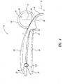
- FIGs 1-5 illustrate a handheld food slicer 10 according to one embodiment which includes a first handle 20, a second handle 30 and blade members 50.
- the slicer 10 further includes a pivot pin 40 for rotatably coupling the first handle 20 and the second handle 30 together about a central rotation axis R.
- a spring 60 biases the handles 20, 30 away from each other such that the slicer 10 is urged towards a generally expanded configuration E ( Figures 1 and 3 ) in which it is configured to insertably receive food items.
- a respective first end 21, 31 of the first and the second handles 20, 30 interoperate to limit the range of movement of the slicer 10 to the expanded configuration E.
- the slicer 10 is sized and its range of movement is limited such that it may fit comfortably in the grasp of an average sized hand throughout operation.
- a user may effortlessly grasp the slicer 10 in one hand and apply a force or pressure to overcome the bias of the spring 60 and transition the slicer 10 from the expanded configuration E to a compressed configuration C ( Figure 4 ).
- the spring 60 urges the handles 20, 30 back toward the expanded configuration E.
- the slicer 10 is selectively and repeatably movable between the expanded configuration E and the compressed configuration C by the intermittent application of force or pressure (i.e., by squeezing and releasing the handles 20, 30).
- Each of the handles 20, 30 is generally elongated and includes the respective first end 21, 31 and a respective second end 22, 32 (also referred to as a distal end).
- a connection structure is located proximate the first end 21 of the first handle 20 for coupling or mating the first handle 20 to the second handle 30.
- the connection structure may take the form of upstanding lugs 23 having pivot apertures 24 sized to receive the pivot pin 40.
- the pivot pin 40 may comprise, for example, a multi-part structure including complementary threaded pin members 40a, 40b.
- the lugs 23 may be spaced apart at a distance sufficient to receive the spring 60 therebetween.
- the spring 60 may be a helical torsion spring, a compression spring or the like.
- a connection structure is similarly located proximate the first end 31 of the second handle 30.
- the connection structure of the second handle 30 may likewise take the form of upstanding lugs 33 having pivot apertures 34 sized to receive the pivot pin 40.
- the lugs 33 of the second handle 30 may be positioned to fit between the lugs 23 of the first handle 20, as illustrated in Figure 5 , or in alternate embodiments, may be positioned to fall outside the lugs 23 of the first handle 20.
- each of the handles 20, 30 is illustrated as including two separate lugs 23, 33, either handle 20, 30 may include a single centrally located lug configured to be received between a pair of lugs of the opposing handle. In such an embodiment, two axially offset springs may be utilized instead of a single centrally located spring 60.
- a plurality of elongated fingers 26 are located at the second end 22 of the first handle 20.
- the fingers 26 are separated from each other by blade receiving slots 27.
- the blade receiving slots 27 have a width approximately equal to a corresponding blade member 50 coupled to the second end 32 of the second handle 30.
- the handheld food slicer 10 may include more or fewer fingers 26.
- a width of the fingers 26 may vary in accordance with a desired width of sliced food items. For example, thinner fingers 26 may be provided for applications in which thinly sliced food items are desired. Conversely, wider fingers 26 may be provided for applications in which thicker sliced food items are desired.
- the fingers 26 may extend seamlessly from a base of the first handle 20 such that an outer surface of the first handle 20 appears uninterrupted.
- the second handle 30 may also include a contoured outer surface that likewise appears uninterrupted and which may be complementarily shaped with respect to the first handle 20.
- the outer surface of the handles 20, 30 may be complementarily shaped to reflect a food item for which the slicer 10 is particularly adapted to slice.
- a slicer 10 particularly adapted to receive and slice bananas may include handles 20, 30 having outer surfaces that reflect part of a banana, as illustrated in Figure 3 .
- Other examples include a carrot shaped slicer for slicing carrots, a celery shaped slicer for slicing celery and a cucumber shaped slicer for slicing cucumbers.
- blade members 50 are coupled to the second end 32 of the second handle 30.
- the blade members 50 are spaced along a central axis A to align with the blade receiving slots 27 of the first handle 20.
- the blade members 50 and hence blade receiving slots 27 may be spaced in equal intervals, as illustrated, or in alternate embodiments may be irregularly spaced.
- Each of the blade members 50 includes a blade edge profile 56 that generally corresponds to the shape of a food item to be sliced.
- each blade member 50 may include an arcuate or a circular blade edge profile 56 corresponding to a shape of a food item having a generally circular cross-sectional profile, such as, for example, a banana.
- the blade members 50 and fingers 26 are positioned to collectively define a food receiving passageway P that extends generally transverse to a length of the elongated handles 20, 30.
- the blade edge profiles 56 may comprise closed profiles, such as complete circular or elliptical profiles. In other embodiments, the blade edge profiles 56 may comprise open profiles.
- the embodiment illustrated in Figures 6A-6C has blade members 50 each including a u-shaped blade edge profile 56 which is bridged or capped by a portion 28 of a respective finger 26 of the first handle 20 to form the food receiving passageway P. In this manner, a portion 28 of the fingers 26 may cooperate with the blade members 50 to collectively define the food receiving passageway P.
- a curvilinear portion 28 of the fingers 26 of the first handle 20 cooperates with the blade members 50 to collectively define a substantially cylindrical food receiving passageway P extending along central axis A.
- Each blade member 50 further includes a structure for coupling to the second handle 30.
- This structure may comprise, for example, a protruding portion 52 adapted to be received by or otherwise coupled to the second handle 30.
- the blade members 50 may be attached to the second handle 30 by clips, snaps, detents or other fastening structures or may be formed integrally therewith.
- the second handle 30 may be formed around the protruding portion 52 of each blade member 50 via a molding process.
- the blade members 50 may further include one or more apertures 54 for receiving material of the second handle 30 during a molding process to facilitate secure attachment.
- the food slicer 10 is configured to be held initially in an expanded configuration E.
- the second end 22 (or distal end) of the first handle 20 and the second end 32 (or distal end) of the second handle 30 are spaced apart under the bias of spring 60 such that the fingers 26 of the first handle 20 are positioned to one side of the food receiving passageway P.
- the blade members 50 align with and at least partially engage the blade receiving slots 27 between the fingers 26.
- food items may be inserted in the food receiving passageway P for subsequent slicing. More particularly, a user may grasp the slicer 10 with one hand and a food item with the other.
- the user may then insert the food item into the receiving passageway P and position the slicer 10 with the food item therein in various orientations prior to slicing. For example, a user may insert a banana into the food receiving passageway P and position the slicer 10 over a bowl of cereal for subsequent placement of sliced banana pieces in the bowl directly.
- the handheld food slicer 10 is transitionable from the expanded configuration E to a compressed configuration C, as indicated by the arrow labeled 70.
- the slicer 10 may be moved to the compressed configuration C by grasping the slicer 10 in the palm of one's hand and squeezing the handles 20, 30 to overcome the bias of the spring 60 and bring the second ends 22, 32 (or distal ends) of the handles 20, 30 relatively closer together.
- the spring 60 may be sized and/or shaped such that the spring bias is easily overcome by a moderate squeezing action. In this manner, the slicer 10 is particularly well suited for one-handed operation.
- the fingers 26 of the first handle 20 pass through the food receiving passageway P adjacent the blade members 50.
- the fingers 26 push the food item into engagement with the blade edge profile 56 of each blade member 50.
- the blade members 50 penetrate the food item and cut the same into sliced pieces.
- the slicer 10 may be manipulated during the slicing process to various orientations. Accordingly, a user can selectively place sliced food products into storage containers or onto prepared dishes, for example, without additional handling.
- the slicer 10 thus provides a particularly versatile food slicing mechanism.
Landscapes
- Engineering & Computer Science (AREA)
- Life Sciences & Earth Sciences (AREA)
- Forests & Forestry (AREA)
- Mechanical Engineering (AREA)
- Food Science & Technology (AREA)
- Food-Manufacturing Devices (AREA)
Claims (7)
- Trancheur alimentaire tenu manuellement (10), comprenant :- une première poignée (20) comportant une pluralité de doigts allongés (26), chaque doigt (26) étant séparé d'un doigt adjacent (26) par une fente de réception de lame (27) ;- une seconde poignée (30) couplée de façon mobile à la première poignée (20) ; et- une pluralité d'éléments à lame (50) couplés à la seconde poignée (30) en alignement espacé avec la fente de réception de lames (27) pour s'accoupler avec les doigts (26) pour définir collectivement une voie de passage de réception d'aliment (P) lorsque les première et seconde poignées (20, 30) sont dans une configuration déployée dans laquelle une extrémité distale (22) de la première poignée (20) est au moins partiellement espacée d'une extrémité distale (32) de la seconde poignée (30), les doigts (26) de la première poignée (30) étant configurés pour passer à travers la voie de passage de réception d'aliment (P) de façon adjacente aux éléments à lame (50) lorsque les première et seconde poignées (20, 30) se déplacent à partir de la configuration déployée vers une configuration comprimée dans laquelle l'extrémité distale (22, 32) de chacune des première et seconde poignées (20, 30) est relativement plus proche de l'autre,
caractérisé en ce que les éléments à lame (50) et les doigts (26) sont positionnés pour définir collectivement la voie de passage de réception d'aliment (P),
dans lequel la voie de passage de réception d'aliment (P) est sensiblement cylindrique ou dans lequel chaque élément à lame (50) comprend un profil de bord de lame arqué ou circulaire (56), dans lequel le profil de bord de lame (56) est un profil fermé, tel que des profils circulaires ou elliptiques complets. - Trancheur alimentaire tenu manuellement (10) selon la revendication 1, comprenant en outre :- un ressort (60) pour solliciter les première et seconde poignées (20, 30) vers la configuration déployée.
- Trancheur alimentaire tenu manuellement (10) selon la revendication 1 ou 2, comprenant en outre :- une goupille de pivotement (40) pour coupler de façon rotative la seconde poignée (30) à la première poignée (20).
- Trancheur alimentaire tenu manuellement (10) selon une quelconque des revendications précédentes, dans lequel une partie curviligne de chacun des doigts (26) coopère avec les éléments à lame (50) pour définir collectivement la voie de passage de réception d'aliment (50).
- Trancheur alimentaire tenu manuellement (10) selon une quelconque des revendications précédentes, dans lequel l'extrémité distale (32) de la seconde poignée (30) est formée autour d'une partie de chacun des éléments à lame (50) pour fixer de façon rigide les éléments à lame (50) à celle-ci.
- Trancheur alimentaire tenu manuellement (10) selon une quelconque des revendications précédentes, dans lequel les éléments à lame (50) sont espacés de façon égale le long d'un axe central (A) de la voie de passage de réception d'aliment (P).
- Procédé pour l'utilisation dans le découpage en tranche d'un article alimentaire avec un trancheur alimentaire tenu manuellement (10) selon une des revendications 1 à 6 avec une main, le procédé comprenant :- l'installation de la première poignée (20) du trancheur alimentaire (10) dans une main, avec l'extrémité distale (22) de la première poignée (20) en saillie au-delà de la main,- la retenue de la seconde poignée (30) du trancheur alimentaire (10) avec au moins un doigt de la même main, avec l'extrémité distale (32) de la seconde poignée (30) en saillie au-delà de la main,- le positionnement d'au moins une partie de l'article alimentaire entre les doigts (26) et les éléments à lame (50) ; et- le serrage de la seconde partie de poignée (30) vers la première poignée (20) pour faire en sorte que les doigts (26) et les éléments à lame (50) se rapprochent les uns des autres jusqu'à ce que la partie de l'article alimentaire ait été tranchée par les éléments à lame (50).
Applications Claiming Priority (2)
| Application Number | Priority Date | Filing Date | Title |
|---|---|---|---|
| US30341910P | 2010-02-11 | 2010-02-11 | |
| PCT/US2011/022861 WO2011100126A1 (fr) | 2010-02-11 | 2011-01-28 | Trancheuse d'aliments de poche |
Publications (2)
| Publication Number | Publication Date |
|---|---|
| EP2533954A1 EP2533954A1 (fr) | 2012-12-19 |
| EP2533954B1 true EP2533954B1 (fr) | 2014-06-11 |
Family
ID=43858046
Family Applications (1)
| Application Number | Title | Priority Date | Filing Date |
|---|---|---|---|
| EP20110703328 Not-in-force EP2533954B1 (fr) | 2010-02-11 | 2011-01-28 | Dispositif tenu manuellement pour la coupe des alliments |
Country Status (7)
| Country | Link |
|---|---|
| US (1) | US9186806B2 (fr) |
| EP (1) | EP2533954B1 (fr) |
| AU (1) | AU2011216160B2 (fr) |
| CA (1) | CA2788353C (fr) |
| DK (1) | DK2533954T3 (fr) |
| ES (1) | ES2496769T3 (fr) |
| WO (1) | WO2011100126A1 (fr) |
Families Citing this family (11)
| Publication number | Priority date | Publication date | Assignee | Title |
|---|---|---|---|---|
| US20120017731A1 (en) * | 2010-07-23 | 2012-01-26 | Mastroianni Michael R | Slicer for food items |
| US9242384B2 (en) | 2012-05-14 | 2016-01-26 | Culinary Expressions Inc. | Food slicer |
| US9694506B2 (en) * | 2013-01-25 | 2017-07-04 | Edlund Company, Llc | Food-product slicers having food-product cradles |
| CN103586917A (zh) * | 2013-11-04 | 2014-02-19 | 杨杰 | 一种瓜果切片器 |
| US9486098B2 (en) * | 2014-04-04 | 2016-11-08 | King's Flair Development Ltd. | Tool for preparing an avocado |
| GB2511991B (en) * | 2014-06-11 | 2015-11-11 | Imre Ivan Szilagyi | Bite Slicer Apparatus |
| CN105397857B (zh) * | 2015-11-27 | 2018-03-23 | 南通江海港建设工程有限公司 | 切片装置 |
| CN106913186B (zh) * | 2015-12-24 | 2019-08-13 | 科劲发展有限公司 | 食物加工装置 |
| USD863872S1 (en) * | 2018-10-25 | 2019-10-22 | Pian Chen | Melon cutter |
| US10625434B1 (en) * | 2019-07-29 | 2020-04-21 | Dana Nadeau | Tomato dicing assembly and method of use |
| CN113664897B (zh) * | 2021-08-06 | 2022-10-28 | 海南师范大学 | 一种海巴戟切片装置 |
Family Cites Families (29)
| Publication number | Priority date | Publication date | Assignee | Title |
|---|---|---|---|---|
| US255429A (en) * | 1882-03-28 | Feed-cutter | ||
| US550483A (en) | 1895-11-26 | Ob masticating implement | ||
| US1107950A (en) * | 1913-08-22 | 1914-08-18 | Joseph John Holsen | Watch-charm. |
| US1113105A (en) * | 1914-03-16 | 1914-10-06 | Deman Klous Mfg Company | Cutter for cigar-tips. |
| US1177098A (en) * | 1915-04-30 | 1916-03-28 | Bates And Bacon | Cigar-cutter. |
| US1504589A (en) * | 1923-11-08 | 1924-08-12 | William G Wagner | Cigar cutter |
| US2006023A (en) * | 1929-10-09 | 1935-06-25 | Winthrop Chem Co Inc | Medicinal preparation |
| US2288385A (en) * | 1941-10-29 | 1942-06-30 | Charles L Beard | Rivet cutter |
| US2516959A (en) * | 1945-04-30 | 1950-08-01 | Ward I Coull | Dehorner |
| US2527735A (en) * | 1946-01-28 | 1950-10-31 | Johnson Elvin | Rivet cutter |
| US2826355A (en) * | 1952-12-23 | 1958-03-11 | Laval Separator Co De | Centrifugal separator |
| US3164899A (en) * | 1961-07-11 | 1965-01-12 | Douglas D Raze | Compression type tool |
| US3883953A (en) * | 1973-03-08 | 1975-05-20 | James W Saullo | Decorative ribbon shredder |
| US4092774A (en) * | 1977-01-21 | 1978-06-06 | Homer Watts | Plastic tube cutter |
| US4158914A (en) * | 1978-05-04 | 1979-06-26 | Kurtz Thomas D | Hand shear for opening dispensing cartridges |
| US4393588A (en) * | 1981-03-09 | 1983-07-19 | Elpo Industries, Inc. | Food mincer |
| SE8406388D0 (sv) * | 1984-12-14 | 1984-12-14 | Laux Friedrich G | Zweischneidiger kabelschneider |
| US4742616A (en) * | 1986-12-16 | 1988-05-10 | Hilti Aktiengesellschaft | Cutting device |
| US5035056A (en) | 1989-12-12 | 1991-07-30 | William Sheffield | Banana slicer |
| US4976029A (en) * | 1990-01-12 | 1990-12-11 | Kennedy Thomas W | Hot dog cutter apparatus and method |
| US5499578A (en) | 1995-02-23 | 1996-03-19 | Payne; Patricia K. | Sausage cutter |
| US6123001A (en) * | 1998-02-11 | 2000-09-26 | Owen Oil Tools, Inc. | Detonating cord cutter |
| US5937523A (en) * | 1998-04-30 | 1999-08-17 | Van Keppel; Kurt | Cigar cutter |
| DE60106408D1 (de) * | 2000-04-04 | 2004-11-18 | Wenco Llc New York | Mehrklingenschneidegerät |
| FR2861262B1 (fr) * | 2003-10-24 | 2006-09-22 | Credo | Dispositif coupe-cigares |
| US20060230892A1 (en) * | 2005-04-14 | 2006-10-19 | Carlos Osuna | Banana chip maker |
| US7346986B2 (en) * | 2006-02-23 | 2008-03-25 | Rain Bird Corporation | Cutting tool for flexible conduit |
| US7266894B1 (en) | 2006-05-16 | 2007-09-11 | John Robert Hinckley | Apparatus for slicing fruit and other items |
| US8181560B2 (en) * | 2009-10-27 | 2012-05-22 | Progressive International Corporation | Food processing tool |
-
2011
- 2011-01-28 WO PCT/US2011/022861 patent/WO2011100126A1/fr not_active Ceased
- 2011-01-28 ES ES11703328.2T patent/ES2496769T3/es active Active
- 2011-01-28 EP EP20110703328 patent/EP2533954B1/fr not_active Not-in-force
- 2011-01-28 US US13/016,168 patent/US9186806B2/en active Active
- 2011-01-28 AU AU2011216160A patent/AU2011216160B2/en not_active Ceased
- 2011-01-28 DK DK11703328T patent/DK2533954T3/da active
- 2011-01-28 CA CA2788353A patent/CA2788353C/fr not_active Expired - Fee Related
Also Published As
| Publication number | Publication date |
|---|---|
| AU2011216160B2 (en) | 2016-10-13 |
| DK2533954T3 (da) | 2014-09-15 |
| AU2011216160A1 (en) | 2012-08-30 |
| CA2788353A1 (fr) | 2011-08-18 |
| EP2533954A1 (fr) | 2012-12-19 |
| CA2788353C (fr) | 2017-09-19 |
| ES2496769T3 (es) | 2014-09-19 |
| WO2011100126A1 (fr) | 2011-08-18 |
| US20110192036A1 (en) | 2011-08-11 |
| US9186806B2 (en) | 2015-11-17 |
Similar Documents
| Publication | Publication Date | Title |
|---|---|---|
| EP2533954B1 (fr) | Dispositif tenu manuellement pour la coupe des alliments | |
| CA2355225C (fr) | Robot culinaire portatif | |
| US7690285B2 (en) | Manual safety vegetable cutter | |
| US6619194B1 (en) | Omni-bearing peeler | |
| US6318222B1 (en) | Apparatus and method for uniform even slicing | |
| EP1955628B1 (fr) | Trancheuse et râpe pour aliments | |
| EP3184006B1 (fr) | Dispositif de traitement d'aliments | |
| US20140230253A1 (en) | Handheld kitchen utensil | |
| WO2010101866A1 (fr) | Trancheuse d'aliments | |
| EP3213892B1 (fr) | Dispositif de retenue des aliments pour une trancheuse d'aliments, et trancheuse d'aliments | |
| US20150075012A1 (en) | Outil a main perfectionne | |
| EP1793720A1 (fr) | Ustensile de cuisine multi-usage | |
| US20070144326A1 (en) | Safety cutter for cutting vegetables into spirals | |
| US10933543B2 (en) | Multipurpose scissors | |
| US20120017731A1 (en) | Slicer for food items | |
| US5899133A (en) | Frozen hamburger patty separator | |
| US3376639A (en) | Pinching knife | |
| US20160106265A1 (en) | Spatula Knife Utensil | |
| US20150151441A1 (en) | Effortless kitchen knife | |
| US8887608B1 (en) | Cleaver and cutting board combination with self-locking hinge | |
| KR20170000400U (ko) | 파 절단 장치 | |
| JP3240431U (ja) | 手動式食品スライサー | |
| KR101024682B1 (ko) | 다기능 주방용 슬라이서 | |
| KR20110105267A (ko) | 마늘 파 세절기 | |
| US20050005783A1 (en) | Device for cutting vegetables into ribbons or into strips including housing therefor |
Legal Events
| Date | Code | Title | Description |
|---|---|---|---|
| PUAI | Public reference made under article 153(3) epc to a published international application that has entered the european phase |
Free format text: ORIGINAL CODE: 0009012 |
|
| 17P | Request for examination filed |
Effective date: 20120726 |
|
| AK | Designated contracting states |
Kind code of ref document: A1 Designated state(s): AL AT BE BG CH CY CZ DE DK EE ES FI FR GB GR HR HU IE IS IT LI LT LU LV MC MK MT NL NO PL PT RO RS SE SI SK SM TR |
|
| RAP1 | Party data changed (applicant data changed or rights of an application transferred) |
Owner name: CHEF'N CORPORATION |
|
| RIN1 | Information on inventor provided before grant (corrected) |
Inventor name: HOLCOMB, DAVID, A. Inventor name: KRUS, MATTHEW |
|
| DAX | Request for extension of the european patent (deleted) | ||
| 17Q | First examination report despatched |
Effective date: 20130522 |
|
| RIN1 | Information on inventor provided before grant (corrected) |
Inventor name: HOLCOMB, DAVID, A. Inventor name: KRUS, MATTHEW |
|
| GRAP | Despatch of communication of intention to grant a patent |
Free format text: ORIGINAL CODE: EPIDOSNIGR1 |
|
| INTG | Intention to grant announced |
Effective date: 20140103 |
|
| GRAS | Grant fee paid |
Free format text: ORIGINAL CODE: EPIDOSNIGR3 |
|
| GRAA | (expected) grant |
Free format text: ORIGINAL CODE: 0009210 |
|
| AK | Designated contracting states |
Kind code of ref document: B1 Designated state(s): AL AT BE BG CH CY CZ DE DK EE ES FI FR GB GR HR HU IE IS IT LI LT LU LV MC MK MT NL NO PL PT RO RS SE SI SK SM TR |
|
| REG | Reference to a national code |
Ref country code: GB Ref legal event code: FG4D |
|
| REG | Reference to a national code |
Ref country code: CH Ref legal event code: EP |
|
| REG | Reference to a national code |
Ref country code: IE Ref legal event code: FG4D |
|
| REG | Reference to a national code |
Ref country code: AT Ref legal event code: REF Ref document number: 672014 Country of ref document: AT Kind code of ref document: T Effective date: 20140715 |
|
| REG | Reference to a national code |
Ref country code: DE Ref legal event code: R096 Ref document number: 602011007592 Country of ref document: DE Effective date: 20140724 |
|
| REG | Reference to a national code |
Ref country code: SE Ref legal event code: TRGR |
|
| REG | Reference to a national code |
Ref country code: DK Ref legal event code: T3 Effective date: 20140911 |
|
| REG | Reference to a national code |
Ref country code: ES Ref legal event code: FG2A Ref document number: 2496769 Country of ref document: ES Kind code of ref document: T3 Effective date: 20140919 |
|
| PG25 | Lapsed in a contracting state [announced via postgrant information from national office to epo] |
Ref country code: NO Free format text: LAPSE BECAUSE OF FAILURE TO SUBMIT A TRANSLATION OF THE DESCRIPTION OR TO PAY THE FEE WITHIN THE PRESCRIBED TIME-LIMIT Effective date: 20140911 Ref country code: LT Free format text: LAPSE BECAUSE OF FAILURE TO SUBMIT A TRANSLATION OF THE DESCRIPTION OR TO PAY THE FEE WITHIN THE PRESCRIBED TIME-LIMIT Effective date: 20140611 Ref country code: GR Free format text: LAPSE BECAUSE OF FAILURE TO SUBMIT A TRANSLATION OF THE DESCRIPTION OR TO PAY THE FEE WITHIN THE PRESCRIBED TIME-LIMIT Effective date: 20140912 |
|
| REG | Reference to a national code |
Ref country code: NL Ref legal event code: VDEP Effective date: 20140611 |
|
| REG | Reference to a national code |
Ref country code: AT Ref legal event code: MK05 Ref document number: 672014 Country of ref document: AT Kind code of ref document: T Effective date: 20140611 |
|
| REG | Reference to a national code |
Ref country code: LT Ref legal event code: MG4D |
|
| PG25 | Lapsed in a contracting state [announced via postgrant information from national office to epo] |
Ref country code: HR Free format text: LAPSE BECAUSE OF FAILURE TO SUBMIT A TRANSLATION OF THE DESCRIPTION OR TO PAY THE FEE WITHIN THE PRESCRIBED TIME-LIMIT Effective date: 20140611 Ref country code: LV Free format text: LAPSE BECAUSE OF FAILURE TO SUBMIT A TRANSLATION OF THE DESCRIPTION OR TO PAY THE FEE WITHIN THE PRESCRIBED TIME-LIMIT Effective date: 20140611 Ref country code: RS Free format text: LAPSE BECAUSE OF FAILURE TO SUBMIT A TRANSLATION OF THE DESCRIPTION OR TO PAY THE FEE WITHIN THE PRESCRIBED TIME-LIMIT Effective date: 20140611 |
|
| PG25 | Lapsed in a contracting state [announced via postgrant information from national office to epo] |
Ref country code: SK Free format text: LAPSE BECAUSE OF FAILURE TO SUBMIT A TRANSLATION OF THE DESCRIPTION OR TO PAY THE FEE WITHIN THE PRESCRIBED TIME-LIMIT Effective date: 20140611 Ref country code: CZ Free format text: LAPSE BECAUSE OF FAILURE TO SUBMIT A TRANSLATION OF THE DESCRIPTION OR TO PAY THE FEE WITHIN THE PRESCRIBED TIME-LIMIT Effective date: 20140611 Ref country code: PT Free format text: LAPSE BECAUSE OF FAILURE TO SUBMIT A TRANSLATION OF THE DESCRIPTION OR TO PAY THE FEE WITHIN THE PRESCRIBED TIME-LIMIT Effective date: 20141013 Ref country code: RO Free format text: LAPSE BECAUSE OF FAILURE TO SUBMIT A TRANSLATION OF THE DESCRIPTION OR TO PAY THE FEE WITHIN THE PRESCRIBED TIME-LIMIT Effective date: 20140611 Ref country code: EE Free format text: LAPSE BECAUSE OF FAILURE TO SUBMIT A TRANSLATION OF THE DESCRIPTION OR TO PAY THE FEE WITHIN THE PRESCRIBED TIME-LIMIT Effective date: 20140611 |
|
| PG25 | Lapsed in a contracting state [announced via postgrant information from national office to epo] |
Ref country code: PL Free format text: LAPSE BECAUSE OF FAILURE TO SUBMIT A TRANSLATION OF THE DESCRIPTION OR TO PAY THE FEE WITHIN THE PRESCRIBED TIME-LIMIT Effective date: 20140611 Ref country code: NL Free format text: LAPSE BECAUSE OF FAILURE TO SUBMIT A TRANSLATION OF THE DESCRIPTION OR TO PAY THE FEE WITHIN THE PRESCRIBED TIME-LIMIT Effective date: 20140611 Ref country code: AT Free format text: LAPSE BECAUSE OF FAILURE TO SUBMIT A TRANSLATION OF THE DESCRIPTION OR TO PAY THE FEE WITHIN THE PRESCRIBED TIME-LIMIT Effective date: 20140611 Ref country code: IS Free format text: LAPSE BECAUSE OF FAILURE TO SUBMIT A TRANSLATION OF THE DESCRIPTION OR TO PAY THE FEE WITHIN THE PRESCRIBED TIME-LIMIT Effective date: 20141011 |
|
| REG | Reference to a national code |
Ref country code: DE Ref legal event code: R097 Ref document number: 602011007592 Country of ref document: DE |
|
| PLBE | No opposition filed within time limit |
Free format text: ORIGINAL CODE: 0009261 |
|
| STAA | Information on the status of an ep patent application or granted ep patent |
Free format text: STATUS: NO OPPOSITION FILED WITHIN TIME LIMIT |
|
| 26N | No opposition filed |
Effective date: 20150312 |
|
| REG | Reference to a national code |
Ref country code: DE Ref legal event code: R097 Ref document number: 602011007592 Country of ref document: DE Effective date: 20150312 |
|
| PG25 | Lapsed in a contracting state [announced via postgrant information from national office to epo] |
Ref country code: SI Free format text: LAPSE BECAUSE OF FAILURE TO SUBMIT A TRANSLATION OF THE DESCRIPTION OR TO PAY THE FEE WITHIN THE PRESCRIBED TIME-LIMIT Effective date: 20140611 |
|
| REG | Reference to a national code |
Ref country code: CH Ref legal event code: PL |
|
| PG25 | Lapsed in a contracting state [announced via postgrant information from national office to epo] |
Ref country code: LU Free format text: LAPSE BECAUSE OF FAILURE TO SUBMIT A TRANSLATION OF THE DESCRIPTION OR TO PAY THE FEE WITHIN THE PRESCRIBED TIME-LIMIT Effective date: 20150128 |
|
| PG25 | Lapsed in a contracting state [announced via postgrant information from national office to epo] |
Ref country code: MC Free format text: LAPSE BECAUSE OF FAILURE TO SUBMIT A TRANSLATION OF THE DESCRIPTION OR TO PAY THE FEE WITHIN THE PRESCRIBED TIME-LIMIT Effective date: 20140611 |
|
| PG25 | Lapsed in a contracting state [announced via postgrant information from national office to epo] |
Ref country code: LI Free format text: LAPSE BECAUSE OF NON-PAYMENT OF DUE FEES Effective date: 20150131 Ref country code: CH Free format text: LAPSE BECAUSE OF NON-PAYMENT OF DUE FEES Effective date: 20150131 |
|
| REG | Reference to a national code |
Ref country code: IE Ref legal event code: MM4A |
|
| PG25 | Lapsed in a contracting state [announced via postgrant information from national office to epo] |
Ref country code: IE Free format text: LAPSE BECAUSE OF NON-PAYMENT OF DUE FEES Effective date: 20150128 |
|
| PG25 | Lapsed in a contracting state [announced via postgrant information from national office to epo] |
Ref country code: BE Free format text: LAPSE BECAUSE OF NON-PAYMENT OF DUE FEES Effective date: 20160131 |
|
| REG | Reference to a national code |
Ref country code: FR Ref legal event code: PLFP Year of fee payment: 6 |
|
| PGRI | Patent reinstated in contracting state [announced from national office to epo] |
Ref country code: BE Effective date: 20160629 |
|
| PG25 | Lapsed in a contracting state [announced via postgrant information from national office to epo] |
Ref country code: MT Free format text: LAPSE BECAUSE OF FAILURE TO SUBMIT A TRANSLATION OF THE DESCRIPTION OR TO PAY THE FEE WITHIN THE PRESCRIBED TIME-LIMIT Effective date: 20140611 |
|
| REG | Reference to a national code |
Ref country code: FR Ref legal event code: PLFP Year of fee payment: 7 |
|
| PGFP | Annual fee paid to national office [announced via postgrant information from national office to epo] |
Ref country code: FI Payment date: 20170127 Year of fee payment: 7 Ref country code: SE Payment date: 20170127 Year of fee payment: 7 |
|
| PG25 | Lapsed in a contracting state [announced via postgrant information from national office to epo] |
Ref country code: SM Free format text: LAPSE BECAUSE OF FAILURE TO SUBMIT A TRANSLATION OF THE DESCRIPTION OR TO PAY THE FEE WITHIN THE PRESCRIBED TIME-LIMIT Effective date: 20140611 Ref country code: HU Free format text: LAPSE BECAUSE OF FAILURE TO SUBMIT A TRANSLATION OF THE DESCRIPTION OR TO PAY THE FEE WITHIN THE PRESCRIBED TIME-LIMIT; INVALID AB INITIO Effective date: 20110128 Ref country code: BG Free format text: LAPSE BECAUSE OF FAILURE TO SUBMIT A TRANSLATION OF THE DESCRIPTION OR TO PAY THE FEE WITHIN THE PRESCRIBED TIME-LIMIT Effective date: 20140611 |
|
| PGFP | Annual fee paid to national office [announced via postgrant information from national office to epo] |
Ref country code: DK Payment date: 20170125 Year of fee payment: 7 |
|
| PG25 | Lapsed in a contracting state [announced via postgrant information from national office to epo] |
Ref country code: CY Free format text: LAPSE BECAUSE OF FAILURE TO SUBMIT A TRANSLATION OF THE DESCRIPTION OR TO PAY THE FEE WITHIN THE PRESCRIBED TIME-LIMIT Effective date: 20140611 |
|
| PGFP | Annual fee paid to national office [announced via postgrant information from national office to epo] |
Ref country code: IT Payment date: 20170124 Year of fee payment: 7 |
|
| PG25 | Lapsed in a contracting state [announced via postgrant information from national office to epo] |
Ref country code: TR Free format text: LAPSE BECAUSE OF FAILURE TO SUBMIT A TRANSLATION OF THE DESCRIPTION OR TO PAY THE FEE WITHIN THE PRESCRIBED TIME-LIMIT Effective date: 20140611 |
|
| REG | Reference to a national code |
Ref country code: FR Ref legal event code: PLFP Year of fee payment: 8 |
|
| PGFP | Annual fee paid to national office [announced via postgrant information from national office to epo] |
Ref country code: BE Payment date: 20180129 Year of fee payment: 8 |
|
| PG25 | Lapsed in a contracting state [announced via postgrant information from national office to epo] |
Ref country code: MK Free format text: LAPSE BECAUSE OF FAILURE TO SUBMIT A TRANSLATION OF THE DESCRIPTION OR TO PAY THE FEE WITHIN THE PRESCRIBED TIME-LIMIT Effective date: 20140611 |
|
| REG | Reference to a national code |
Ref country code: DK Ref legal event code: EBP Effective date: 20180131 |
|
| REG | Reference to a national code |
Ref country code: SE Ref legal event code: EUG |
|
| PG25 | Lapsed in a contracting state [announced via postgrant information from national office to epo] |
Ref country code: SE Free format text: LAPSE BECAUSE OF NON-PAYMENT OF DUE FEES Effective date: 20180129 Ref country code: AL Free format text: LAPSE BECAUSE OF FAILURE TO SUBMIT A TRANSLATION OF THE DESCRIPTION OR TO PAY THE FEE WITHIN THE PRESCRIBED TIME-LIMIT Effective date: 20140611 Ref country code: FI Free format text: LAPSE BECAUSE OF NON-PAYMENT OF DUE FEES Effective date: 20180128 |
|
| PG25 | Lapsed in a contracting state [announced via postgrant information from national office to epo] |
Ref country code: DK Free format text: LAPSE BECAUSE OF NON-PAYMENT OF DUE FEES Effective date: 20180131 |
|
| PG25 | Lapsed in a contracting state [announced via postgrant information from national office to epo] |
Ref country code: IT Free format text: LAPSE BECAUSE OF NON-PAYMENT OF DUE FEES Effective date: 20180128 |
|
| PGFP | Annual fee paid to national office [announced via postgrant information from national office to epo] |
Ref country code: GB Payment date: 20190128 Year of fee payment: 9 Ref country code: ES Payment date: 20190201 Year of fee payment: 9 Ref country code: DE Payment date: 20190129 Year of fee payment: 9 Ref country code: FR Payment date: 20190125 Year of fee payment: 9 |
|
| REG | Reference to a national code |
Ref country code: BE Ref legal event code: MM Effective date: 20190131 |
|
| PG25 | Lapsed in a contracting state [announced via postgrant information from national office to epo] |
Ref country code: BE Free format text: LAPSE BECAUSE OF NON-PAYMENT OF DUE FEES Effective date: 20190131 |
|
| REG | Reference to a national code |
Ref country code: DE Ref legal event code: R119 Ref document number: 602011007592 Country of ref document: DE |
|
| GBPC | Gb: european patent ceased through non-payment of renewal fee |
Effective date: 20200128 |
|
| PG25 | Lapsed in a contracting state [announced via postgrant information from national office to epo] |
Ref country code: FR Free format text: LAPSE BECAUSE OF NON-PAYMENT OF DUE FEES Effective date: 20200131 Ref country code: DE Free format text: LAPSE BECAUSE OF NON-PAYMENT OF DUE FEES Effective date: 20200801 Ref country code: GB Free format text: LAPSE BECAUSE OF NON-PAYMENT OF DUE FEES Effective date: 20200128 |
|
| REG | Reference to a national code |
Ref country code: ES Ref legal event code: FD2A Effective date: 20210607 |
|
| PG25 | Lapsed in a contracting state [announced via postgrant information from national office to epo] |
Ref country code: ES Free format text: LAPSE BECAUSE OF NON-PAYMENT OF DUE FEES Effective date: 20200129 |