EP2533962B1 - Cheville à expansion - Google Patents
Cheville à expansion Download PDFInfo
- Publication number
- EP2533962B1 EP2533962B1 EP11708694.2A EP11708694A EP2533962B1 EP 2533962 B1 EP2533962 B1 EP 2533962B1 EP 11708694 A EP11708694 A EP 11708694A EP 2533962 B1 EP2533962 B1 EP 2533962B1
- Authority
- EP
- European Patent Office
- Prior art keywords
- expansion
- sleeve
- expansible
- expansion sleeve
- fixing plug
- Prior art date
- Legal status (The legal status is an assumption and is not a legal conclusion. Google has not performed a legal analysis and makes no representation as to the accuracy of the status listed.)
- Active
Links
Images


Classifications
-
- F—MECHANICAL ENGINEERING; LIGHTING; HEATING; WEAPONS; BLASTING
- F16—ENGINEERING ELEMENTS AND UNITS; GENERAL MEASURES FOR PRODUCING AND MAINTAINING EFFECTIVE FUNCTIONING OF MACHINES OR INSTALLATIONS; THERMAL INSULATION IN GENERAL
- F16B—DEVICES FOR FASTENING OR SECURING CONSTRUCTIONAL ELEMENTS OR MACHINE PARTS TOGETHER, e.g. NAILS, BOLTS, CIRCLIPS, CLAMPS, CLIPS OR WEDGES; JOINTS OR JOINTING
- F16B13/00—Dowels or other devices fastened in walls or the like by inserting them in holes made therein for that purpose
- F16B13/12—Separate metal or non-separate or non-metal dowel sleeves fastened by inserting the screw, nail or the like
- F16B13/124—Separate metal or non-separate or non-metal dowel sleeves fastened by inserting the screw, nail or the like fastened by inserting a threaded element, e.g. screw or bolt
-
- F—MECHANICAL ENGINEERING; LIGHTING; HEATING; WEAPONS; BLASTING
- F16—ENGINEERING ELEMENTS AND UNITS; GENERAL MEASURES FOR PRODUCING AND MAINTAINING EFFECTIVE FUNCTIONING OF MACHINES OR INSTALLATIONS; THERMAL INSULATION IN GENERAL
- F16B—DEVICES FOR FASTENING OR SECURING CONSTRUCTIONAL ELEMENTS OR MACHINE PARTS TOGETHER, e.g. NAILS, BOLTS, CIRCLIPS, CLAMPS, CLIPS OR WEDGES; JOINTS OR JOINTING
- F16B13/00—Dowels or other devices fastened in walls or the like by inserting them in holes made therein for that purpose
- F16B13/04—Dowels or other devices fastened in walls or the like by inserting them in holes made therein for that purpose with parts gripping in the hole or behind the reverse side of the wall after inserting from the front
- F16B13/045—Dowels or other devices fastened in walls or the like by inserting them in holes made therein for that purpose with parts gripping in the hole or behind the reverse side of the wall after inserting from the front having axially compressing parts allowing the clamping of an object tightly to the wall
-
- F—MECHANICAL ENGINEERING; LIGHTING; HEATING; WEAPONS; BLASTING
- F16—ENGINEERING ELEMENTS AND UNITS; GENERAL MEASURES FOR PRODUCING AND MAINTAINING EFFECTIVE FUNCTIONING OF MACHINES OR INSTALLATIONS; THERMAL INSULATION IN GENERAL
- F16B—DEVICES FOR FASTENING OR SECURING CONSTRUCTIONAL ELEMENTS OR MACHINE PARTS TOGETHER, e.g. NAILS, BOLTS, CIRCLIPS, CLAMPS, CLIPS OR WEDGES; JOINTS OR JOINTING
- F16B13/00—Dowels or other devices fastened in walls or the like by inserting them in holes made therein for that purpose
- F16B13/04—Dowels or other devices fastened in walls or the like by inserting them in holes made therein for that purpose with parts gripping in the hole or behind the reverse side of the wall after inserting from the front
- F16B13/06—Dowels or other devices fastened in walls or the like by inserting them in holes made therein for that purpose with parts gripping in the hole or behind the reverse side of the wall after inserting from the front combined with expanding sleeve
- F16B13/061—Dowels or other devices fastened in walls or the like by inserting them in holes made therein for that purpose with parts gripping in the hole or behind the reverse side of the wall after inserting from the front combined with expanding sleeve of the buckling type
-
- F—MECHANICAL ENGINEERING; LIGHTING; HEATING; WEAPONS; BLASTING
- F16—ENGINEERING ELEMENTS AND UNITS; GENERAL MEASURES FOR PRODUCING AND MAINTAINING EFFECTIVE FUNCTIONING OF MACHINES OR INSTALLATIONS; THERMAL INSULATION IN GENERAL
- F16B—DEVICES FOR FASTENING OR SECURING CONSTRUCTIONAL ELEMENTS OR MACHINE PARTS TOGETHER, e.g. NAILS, BOLTS, CIRCLIPS, CLAMPS, CLIPS OR WEDGES; JOINTS OR JOINTING
- F16B13/00—Dowels or other devices fastened in walls or the like by inserting them in holes made therein for that purpose
- F16B13/04—Dowels or other devices fastened in walls or the like by inserting them in holes made therein for that purpose with parts gripping in the hole or behind the reverse side of the wall after inserting from the front
- F16B13/08—Dowels or other devices fastened in walls or the like by inserting them in holes made therein for that purpose with parts gripping in the hole or behind the reverse side of the wall after inserting from the front with separate or non-separate gripping parts moved into their final position in relation to the body of the device without further manual operation
- F16B13/0833—Dowels or other devices fastened in walls or the like by inserting them in holes made therein for that purpose with parts gripping in the hole or behind the reverse side of the wall after inserting from the front with separate or non-separate gripping parts moved into their final position in relation to the body of the device without further manual operation with segments or fingers expanding or tilting into an undercut hole
-
- B—PERFORMING OPERATIONS; TRANSPORTING
- B29—WORKING OF PLASTICS; WORKING OF SUBSTANCES IN A PLASTIC STATE IN GENERAL
- B29C—SHAPING OR JOINING OF PLASTICS; SHAPING OF MATERIAL IN A PLASTIC STATE, NOT OTHERWISE PROVIDED FOR; AFTER-TREATMENT OF THE SHAPED PRODUCTS, e.g. REPAIRING
- B29C45/00—Injection moulding, i.e. forcing the required volume of moulding material through a nozzle into a closed mould; Apparatus therefor
- B29C45/16—Making multilayered or multicoloured articles
-
- B—PERFORMING OPERATIONS; TRANSPORTING
- B29—WORKING OF PLASTICS; WORKING OF SUBSTANCES IN A PLASTIC STATE IN GENERAL
- B29L—INDEXING SCHEME ASSOCIATED WITH SUBCLASS B29C, RELATING TO PARTICULAR ARTICLES
- B29L2031/00—Other particular articles
- B29L2031/727—Fastening elements
-
- F—MECHANICAL ENGINEERING; LIGHTING; HEATING; WEAPONS; BLASTING
- F16—ENGINEERING ELEMENTS AND UNITS; GENERAL MEASURES FOR PRODUCING AND MAINTAINING EFFECTIVE FUNCTIONING OF MACHINES OR INSTALLATIONS; THERMAL INSULATION IN GENERAL
- F16B—DEVICES FOR FASTENING OR SECURING CONSTRUCTIONAL ELEMENTS OR MACHINE PARTS TOGETHER, e.g. NAILS, BOLTS, CIRCLIPS, CLAMPS, CLIPS OR WEDGES; JOINTS OR JOINTING
- F16B13/00—Dowels or other devices fastened in walls or the like by inserting them in holes made therein for that purpose
- F16B13/04—Dowels or other devices fastened in walls or the like by inserting them in holes made therein for that purpose with parts gripping in the hole or behind the reverse side of the wall after inserting from the front
- F16B13/08—Dowels or other devices fastened in walls or the like by inserting them in holes made therein for that purpose with parts gripping in the hole or behind the reverse side of the wall after inserting from the front with separate or non-separate gripping parts moved into their final position in relation to the body of the device without further manual operation
- F16B13/0858—Dowels or other devices fastened in walls or the like by inserting them in holes made therein for that purpose with parts gripping in the hole or behind the reverse side of the wall after inserting from the front with separate or non-separate gripping parts moved into their final position in relation to the body of the device without further manual operation with an expansible sleeve or dowel body driven against a tapered or spherical expander plug
Definitions
- the invention relates to a plastic expansion anchor with the features of the preamble of claim 1.
- EP 1 701 046 A1 is an expansion dowel known, which can be introduced into a borehole and spread there for attachment.
- the expansion dowel consists of a tubular expansion sleeve with a spreading area which can be radially expanded by inserting a wood or chipboard screw.
- the spreading area is widened in diameter during spreading by the screw, whereby expansion legs of the expansion area are pressed against the borehole wall.
- the expansion tongues are relatively solid, formed with circular sector-shaped cross sections, so that even with screws with a small diameter as large a radial expansion of the expansion anchor can be achieved.
- the disadvantage is that due to the massive formation of Spreizzache the ability of Spreizzungen to form nodes or hollow in hollow building materials, as for example from the utility model DE 297 04 666 U1 is known, is severely limited.
- An expansion dowel for soft masonry is from the German utility model DE 7 145 271 known.
- This expansion plug consists of a first expansion sleeve made of a hard plastic, which is inserted into a second expansion sleeve made of a soft plastic.
- the first expansion sleeve, which forms the front in the direction of insertion of the expansion anchor is formed as a sleeve-shaped ring member.
- the two expansion sleeves have a common axial guide channel into which a screw can be screwed as a spreading element.
- the screw is, for example, a chipboard screw with a widened in diameter relative to the screw head screw.
- the expansion anchor is first widened and spread in the radial direction during insertion of the screw.
- this expansion anchor is particularly suitable for soft building materials and building materials with cavities, for example, for perforated bricks.
- the spreading behavior in a solid building material is not very advantageous, since a buckling of the expansion area due to the small annular gap between the borehole wall and the expansion anchor is not possible.
- the spreading pressure which can be generated in the radial direction is small, so that the expansion anchor in a solid building material can only generate low holding forces.
- an expansion anchor according to the preamble of claim 1 for attachment in plate-like components is known.
- This generic expansion dowel has two expansion sleeve, which are rotatably connected in an unexpanded state and tensile strength.
- a sliding surface between the two expansion sleeves is present, so that the expansion sleeves of the expansion anchor can be separated from each other and move against each other, wherein they spread the expansion anchor.
- the object of the invention is to propose an expansion anchor, which has improved retention properties in different building materials.
- the plastic expansion anchor according to the invention has a spreading region which can be expanded with a spreading element.
- a substantially extending in the axial direction guide channel is arranged, in which the expansion element can be introduced for spreading the expansion anchor.
- spreading is meant that the expansion region is widened with the expansion element in the radial direction, so that the diameter of a circle circumscribing the cross-section of the expanding expansion dowel is larger than the diameter of a circle circumscribing the cross-section of the non-expanded expansion anchor.
- the expansion element is in particular pin-shaped and is in particular a screw, for example a wood or chipboard screw.
- the expansion anchor comprises at least two expansion sleeves made of plastic, wherein the second expansion sleeve, the first expansion sleeve in an unexpanded state, ie before insertion of the Spreizelements, at least partially wrapped.
- “Made of plastic” means that the expansion sleeves, as well as the expansion dowel, consist essentially of plastic, wherein in principle on or in the expansion anchor and parts of other materials, in particular inserts made of metal, may be provided.
- the first and the second expansion sleeve in the unexpanded state are connected to one another in a rotationally and tension-resistant manner. The connection can be done, for example, form-fitting.
- the first and the second expansion sleeve stabilize each other, in particular in the expansion area, so that they can be spread open together like an expansion sleeve.
- the two expansion sleeves are connected to one another such that a sliding surface is formed in the expansion region between the first expansion sleeve and the second expansion sleeve.
- the two expansion sleeves are two separate bodies that touch, for example, on the sliding surface and adhere to each other. In this case, forms the surface on which the two expansion sleeves touch, the sliding surface.
- an independent layer between the two expansion sleeves may be arranged and act as a sliding surface. This layer is made for example of a plastic which has a low friction with respect to the first and the second expansion sleeve.
- the sliding surface is designed in such a way that when the expansion dowel is being spread, the first expansion sleeve can be released from the second expansion sleeve in the expansion region and move relative to the second expansion sleeve.
- the release can take place partially or substantially completely in the spread region.
- the two expansion sleeves together form a solid and stable expansion area due to the tensile and rotationally fixed connection.
- the two expansion sleeves form in the expansion at least two massive and stable primary expansion tongues, which alone by introducing the expansion element by radial widths, as it is from the expansion anchor of the European patent application EP 1 701 046 A1 is known in a solid building a high expansion pressure and thus generates large holding forces.
- the expansion area is initially radially expanded and spread during insertion of the expansion element, without necessarily leading to a relative displacement or rotation of the two expansion sleeves to each other.
- the Prelixing does not necessarily displace the first expansion sleeve relative to the second expansion sleeve, and the solid and stable primary expansion tongues are urged substantially radially outwardly against the borehole wall only.
- the advantage of the expansion anchor according to the invention is that the massive and stable expansion region formed by the expansion sleeves can be resolved by a relative displacement of the two expansion sleeves to each other along the sliding surfaces. For example, a stable primary spreader tongue with a relatively large, solid cross-section can disintegrate into a number of smaller secondary expansion tongues that are no longer connected to one another in a tension-proof and rotationally fixed manner.
- the secondary expansion tongues have a smaller cross-section with less stability, so that they easily kink, bend or knot, as of the expansion anchor of the publication DE 100 15 902 A1 is known.
- the expansion area can be spread much more radially after separation of the two expansion sleeves, as solely by the insertion of the expansion element.
- the relative displacement of the first expansion sleeve to the second expansion sleeve causes the first expansion sleeve no longer stabilizes the second expansion, so that at least a secondary expansion of the second expansion sleeve buckle and / or twist and form a node and / or the first expansion sleeve in the second expansion sleeve is retracted, so that the first expansion sleeve radially expands the second expansion sleeve in addition to the expansion element and presses outward.
- the expansion dowel according to the invention can therefore also be used in hollow building materials or soft masonry and achieved in these materials good holding values.
- the first expansion sleeve can be expanded by the expansion element itself.
- the spreading of the first expansion sleeve is in addition to the spreading of the second expansion sleeve. If the second expansion sleeve is spread by the fact that the first expansion sleeve is retracted into the second expansion sleeve, so that the first expansion sleeve radially expands and pushes the second expansion sleeve in addition to the expansion element, the radial expansion of the second expansion sleeve by the spreadability of the first expansion sleeve increased.
- the Aufsp Son Anlagen the first expansion sleeve also allows screws of different diameters can be taken as a spreading of the first expansion sleeve and positively connected with her, so that the first expansion sleeve can be moved with a screw relative to the second expansion sleeve. Anchoring the expansion anchor in hollow building materials or soft masonry is improved.
- the first expansion sleeve has in its peripheral surface an opening, which facilitates the spreading of the first expansion sleeve in the radial direction.
- the opening may in particular be a longitudinal slot, which does not have to be exactly axial, but may for example be arranged like a helix or is configured in a U-shape.
- the longitudinal slot does not necessarily have to completely penetrate the spreader body radially, but can also be designed as a material weakening, in particular in a groove-like manner or with a sprayed skin.
- a plurality of slots may be provided, which are arranged offset, for example, over the circumference.
- An embodiment of the invention provides that the first expansion sleeve forms a core when forming the second expansion sleeve.
- the second expansion sleeve is injection-molded, for example, from plastic.
- the first expansion sleeve may also be made by injection molding of plastic or otherwise made of plastic.
- An advantage of this type of production is that the first expansion sleeve and the second expansion sleeve do not have to be assembled, but are already assembled after the prototyping of the second expansion sleeve.
- Another advantage is that the second expansion sleeve and / or the first expansion sleeve may have undercuts that would prevent assembly of the first expansion sleeve and the second expansion sleeve.
- the expansion anchor according to the invention can be produced inexpensively in a multi-component injection molding process, wherein first the first expansion sleeve and then the second expansion sleeve or vice versa are produced.
- the first expansion sleeve of the expansion anchor according to the invention is made of a first plastic component and the second expansion sleeve of a second plastic component.
- the two plastic components are different.
- a material combination with low friction is selected in order to be able to displace the first expansion sleeve with little force relative to the second expansion sleeve.
- the plastic component of the first Spreader relatively hard and the second expansion sleeve relatively soft, so that between the borehole wall and the second expansion sleeve a large friction acts, which is greater than the friction in the sliding surface between the two expansion sleeves.
- the second expansion sleeve can be made of a hard, for example fiber-reinforced plastic, which can transmit large expansion forces on a borehole wall, while the first expansion sleeve is made of a softer plastic.
- the selected material combination should avoid cold welding, ie a material connection between the expansion sleeves, with high spreading pressure.
- Another aspect is a choice of material with a melting temperature of the plastic component of the second expansion sleeve, which substantially avoids melting of the first expansion sleeve when the expansion sleeve is manufactured as a molded piece on the first expansion sleeve as the core. At least it must be ensured that forms a defined sliding surface between the two expansion sleeves.
- the two plastic components may also consist of substantially the same material.
- the polyamide PA6 can be used for both expansion sleeves.
- the two plastic components may be colored differently, so that a visually appealing design of the expansion anchor is possible. Also, certain color combinations can be used as an indication of the intended use of certain expansion anchors.
- the second expansion sleeve closes the opening.
- closes is meant in particular that the plastic component of the second expansion sleeve, the opening substantially filled, for example, during injection molding of the second expansion sleeve.
- An embodiment of the invention provides that the first and the second expansion sleeve spread in the same direction transverse to the expansion dowel, so for example not rectangular to each other. If the second expansion sleeve in the expansion region is considered as a shell, which surrounds the first expansion sleeve and is divided in the circumferential direction by, for example, two longitudinal slots, it hinders the spreading of the first Expansion sleeve not or at least less, if it spreads in the same direction as the first expansion sleeve.
- the extent of the radial expansion of the second expansion sleeve is increased by the spreading in the same direction.
- a further embodiment of the expansion anchor according to the invention provides that the second expansion sleeve, the first expansion sleeve substantially in the axial direction completely wrapped, whereby the first expansion sleeve is not or only slightly in direct contact with a borehole wall. The first expansion sleeve is then essentially in contact only with the second expansion sleeve against which it is movable. This embodiment of the invention avoids completely or at least largely friction between the first expansion sleeve and the borehole wall, which would hinder the displacement of the first expansion sleeve.
- a further preferred embodiment of the expansion anchor according to the invention provides that the second expansion sleeve has an opening in its peripheral surface, which facilitates a spreading of the second expansion sleeve.
- This opening may for example be formed as a longitudinal slot or V-, U-, S-shaped or oblique. The opening can be penetrated by an elevation of the first expansion sleeve and be closed flat with the plastic component of the first expansion sleeve, so that no cavity is formed, which would reduce the stability of the expansion region.
- the first expansion sleeve extends in the axial direction substantially over the entire expansion region.
- the first expansion sleeve stabilizes the second expansion sleeve in this area.
- the first expansion sleeve can extend over the entire length of the expansion anchor.
- a plurality of secondary expansion tongues are formed on the two expansion sleeves, which are arranged together in the expansion region.
- a plurality of secondary expansion tongues together form a primary expansion tongue, wherein at least two primary expansion tongues are provided in the expansion region.
- the secondary expansion tongues are in particular of columnar or helical design, such that they, when the two expansion sleeves relative to each other and be shifted towards each other, bend slightly, bend and / or twist and form a knot.
- the secondary expansion tongues of the first expansion sleeve and the secondary expansion tongues of the second expansion sleeve are arranged alternately in the circumferential direction.
- the secondary expansion tongues of the two expansion sleeves touch, so that they first stabilize each other. If the expansion sleeves are at least partially released from each other by a relative movement, the secondary expansion tongues in the areas in which they have detached from one another do not interfere with each other during spreading.
- the anti-rotation of the first expansion sleeve with respect to the second expansion sleeve can be effected for example by engaging in grooves or slots ribs.
- the rotation prevents rotation of the first expansion sleeve with a screw designed as a spreading when screwing the screw.
- the second expansion sleeve must be prevented from turning.
- the first expansion sleeve has at least one outwardly projecting longitudinal rib, which engages in a corresponding recess, for example a groove or a slot of the second expansion sleeve.
- the longitudinal rib and the recess form the already described rotation assurance of the first expansion sleeve with respect to the second expansion sleeve.
- the recess weakens a wall of the second expansion sleeve, which facilitates their spreading.
- a slot for example, avoids a circumferentially closed second expansion sleeve, a plurality of slots divide the second expansion sleeve in expansion tongues. Both facilitate the spreading of the second expansion sleeve.
- One or more grooves facilitate stretching and / or tearing of the second expansion sleeve on the groove base, whereby the second expansion sleeve is also easier to spread.
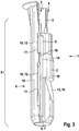
- FIGS. 1 to 3 an inventive expansion dowel 1 is shown in an unexpanded state.
- the expansion anchor 1 has a first expansion sleeve 2 and a second expansion sleeve 3, which encloses the first expansion sleeve 2 substantially.
- the second expansion sleeve 3 is substantially tubular and has a radial flange 4 at an open, rear end.
- the second expansion sleeve 3 extends over the entire length of the first expansion sleeve 2.
- At the rear end is the second expansion sleeve 3 via the first expansion sleeve 2, wherein "back" refers to the insertion of the expansion anchor 1 in a borehole.
- the expansion anchor 1 has an axial center hole as a guide channel 5 for screwing a screw, not shown.
- the two expansion sleeves 2, 3 are designed in the manner of an expansion anchor, so by screwing the screw in the guide channel 5 spreadable.
- the first expansion sleeve 2 it has in its peripheral surface longitudinal slots 6 as openings 7, which are, however, substantially closed by the second expansion sleeve 3.
- the longitudinal slots 6 are located in an axial plane of the first expansion sleeve 2.
- the first expansion sleeve 2 spreads perpendicular to the axial plane in which the longitudinal slots 6 are located.
- the direction in which the first expansion sleeve 2 spreads when screwing a screw can also be understood as a spreading plane.
- the spreading plane is an axial plane of the first expansion sleeve 2, which, as already stated, is perpendicular to the axial plane in which the longitudinal slots 6 are located. If a screw is introduced into the guide channel 5 to the front end of the expansion anchor 1, the two expansion sleeves 2, 3 are not initially moved relative to each other, but the two expansion sleeves 2, 3 are spread exclusively perpendicular to the spreading plane and moved in the radial direction R.
- the expansion plane divides the expansion anchor 1 into two primary expansion tongues 8, which consist of parts of the two expansion sleeves 2, 3 and form the expansion region 9 of the expansion anchor 1.
- the first expansion sleeve 2 Immediately adjacent to the longitudinal slots 6, the first expansion sleeve 2 has outwardly projecting longitudinal ribs 10, pass through the openings 11 of the second expansion sleeve 3 fit and protrude slightly outward on the second expansion sleeve 3. Together with the openings 11 of the second expansion sleeve 3, which they pass through, the longitudinal ribs 10 of the first expansion sleeve 2 form a rotation lock 12 which rotatably holds the first expansion sleeve 2 in the second expansion sleeve 3. In the unexpanded state, the first expansion sleeve 2 is also tensile in the axial direction with the second expansion sleeve 3.
- the second expansion sleeve 3 is perpendicular to their openings 11 spread apart. Since the openings 11 of the second expansion sleeve 3 are located directly next to the longitudinal slots 6 of the first expansion sleeve 2, the first expansion sleeve 2 and the second expansion sleeve 3 spread in the same direction, ie perpendicular to the spreading plane.
- the first expansion sleeve 2 and the second expansion sleeve 3 are made by injection molding of two plastics, for example, the second expansion sleeve 3 made of polypropylene and the first expansion sleeve 2 made of polyamide. So it is the first expansion sleeve 2 and the second expansion sleeve 3 produced by prototyping parts. First, the first expansion sleeve 2 is injected, which is then introduced as a core in an injection mold for injection molding of the second expansion sleeve 3.
- first expansion sleeve 2 and the second expansion sleeve 3 are produced in an injection molding in a multi-component injection molding, wherein first the first expansion sleeve 2 and then the second expansion sleeve 3 are injection-molded.
- first the first expansion sleeve 2 and then the second expansion sleeve 3 are injection-molded.
- a non-illustrated molding is inserted in this case in a cavity of the injection mold, which occupies the volume of the second expansion sleeve 3 in this case.
- the second expansion sleeve 3 has complementary surfaces to surfaces 15, bodies 13, 14 and longitudinal ribs 10 of the first expansion sleeve 2, the longitudinal slots 6 are closed. Openings 11 of the second expansion sleeve 3 are formed by the longitudinal ribs 10 of the first expansion sleeve 2.
- the first expansion sleeve 2 is made of a plastic having a higher melting temperature than the second expansion sleeve 3, so that the core used for injection molding of the second expansion sleeve 3 first expansion sleeve 2 does not melt or melts when the second expansion sleeve 3 is injected around it.
- the two expansion sleeves 2, 3 are thus not in one piece.
- a sliding surface 16 is formed, so that when spreading the expansion dowel 1, the first expansion sleeve 2 can be solved in a spread region 9 of the second expansion sleeve 3 and is movable relative to the second expansion sleeve 3.
- the first expansion sleeve 2 has two spreader 13, 14.
- the further forward spreader 13 is wedge-shaped, it has two mutually opposite wedge or inclined surfaces 15 which extend obliquely forward diagonally.
- the farther back, second spreader 14 is conical, he also expands forward.
- the rear spreader 14, like the front spreader 13, could be wedge-shaped rather than tapered, as well as the front spreader 13 could be tapered rather than wedge-shaped. Other shapes, such as pyramidal spreader are possible (not shown). It is also possible to form the expansion anchor 1 with more than two expansion bodies (not shown).
- a stop of the expansion anchor 1 can be increased in a wellbore in a solid building material.
- a hollow building material cause the expansion body 13, 14 at a displacement of the first expansion sleeve 2 to the rear end of the expansion anchor 1, a larger radial spreading of the second expansion sleeve 3, which for example webs in perforated bricks or plates with the expansion dowel 1 can be better engaged behind.
- the expansion body 13, 14 are formed so that a displacement of the first expansion sleeve 2 in the second expansion sleeve 3 to the rear spreads the second expansion sleeve 3 in addition to the screw. In this case, the first expansion sleeve 2 dissolves along the sliding surface 16 of the second expansion sleeve 3.
- the two primary expansion tongues 8 disintegrate into individual secondary expansion tongues 18, 19 of the two expansion sleeves 2, 3.
- the secondary expansion tongues 19 of the second expansion sleeve 3 are now less stable than the primary expansion tongues 8 so that they are more easily bent and radially expandable.
- a screw for spreading the expansion anchor 1, as already mentioned, a screw, not shown, screwed into the axial guide channel 5.
- the screw spreads the first expansion sleeve 2 and the second expansion sleeve 3 enclosing it in the manner of an expansion anchor.
- the lying on one side of the spreading plane E S parts of the expansion region 9 of the expansion sleeves 2, 3 act together as the primary expansion tongues 8. Since the first expansion sleeve 2 and the second expansion sleeve 3 spread in the same direction, obstructs the first expansion sleeve 2 enclosing the second expansion sleeve third not spreading. As a result of the described spreading, the second expansion sleeve 3 clamps in a borehole. In this state, the two expansion sleeves 2, 3 continue to rotate and tensile strength connected to each other.
- the screw causes a pulling force on the expansion sleeve 2.
- the screw pulls after overcoming a certain axial force, the first expansion sleeve 2 in the second expansion sleeve 3 towards the rear of the radial flange. 4
- the spreading widening 13, 14 of the first expansion sleeve 2 spreading out towards the front spread the secondary expansion tongues 19 of the second expansion sleeve 3 additionally.
- the anchoring of the expansion anchor 1 in a borehole is thereby improved.
- the expansion anchor 1 has a spreading behavior: A borehole in which the expansion anchor 1 is spread open and anchored, for example, widens Sequence of cracking causes a tensile force exerted on the first expansion sleeve 2 by a fastened object loaded screw which is screwed in the first expansion sleeve 2, a further displacement of the first expansion sleeve 2 in the direction of the rear end of the second expansion sleeve 3, which further spreads the second expansion sleeve 3, ie spreads, so that the expansion anchor 1 remains anchored in the borehole with substantially unchanged anchoring force, if this expands, for example, as a result of cracking.
- the second expansion sleeve 3 surrounds the first expansion sleeve 2 over its entire length, only the longitudinal ribs 10 of the first expansion sleeve 2 come into contact with a wall, not shown, of a borehole, also not shown. As a result, almost no friction between the borehole and the first expansion sleeve 2 acts during the spreading, the first expansion sleeve 2 is relatively smooth in the second expansion sleeve 3 slidably.
- the first expansion sleeve 102 of the expansion anchor 101 from the FIG. 4 U-shaped longitudinal folds 117 which extend in the longitudinal direction over a rear to central region of the first expansion sleeve 102.
- the longitudinal folds 117 are arranged opposite each other and face inwards. They extend from a rear end of the first expansion sleeve 102 on the second spreader 114 away across to a rear end of the front spreader 113.
- the longitudinal folds 117 facilitate the spreading of the first expansion sleeve 102 when screwing a screw, not shown, they complement the longitudinal slots 106 in this area.
- inventive expansion dowel 101 is the same design and works in the same way as in Figures 1-3 shown expansion dowel 1. To avoid repetition to explain the FIG. 4 in addition the explanations of the Figures 1-3 referenced.
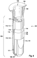
- FIGS. 5 to 8 is another inventive expansion dowel 201 shown.
- the expansion anchor 201 has a first expansion sleeve 202 and a second expansion sleeve 203.
- the first expansion sleeve 202 is made of a softer plastic component
- the second expansion sleeve 203 made of a harder, glass fiber reinforced plastic component.
- the second expansion sleeve 203 encloses the first expansion sleeve 202 in the expansion region 209, wherein the second expansion sleeve 203 has openings 211, which are penetrated by the plastic component of the first expansion sleeve 202.
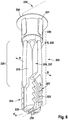
- the first expansion sleeve 202 is made as an injection molded part. In the FIG. 6 is the first expansion sleeve 202 alone, without the second expansion sleeve 203 shown.
- the first expansion sleeve 202 is divided into three areas: at the rear end of the first expansion sleeve 202, a tubular rear sleeve 220 is arranged with a circumferential radial flange 204.
- four wedge-shaped ribs 221 are provided on the tubular sleeve 220, which are distributed in the circumferential direction and extend in the axial direction.
- the wedge-shaped ribs 221 take over the expansion dowel 201 also the function of anti-rotation ribs to secure the expansion anchor 201 against turning in a borehole when a screw is screwed into the expansion anchor 201.
- two circular segment-shaped expansion shells 222 are arranged on the expansion sleeve, which are connected by V-shaped connecting webs 223 together.
- the two expansion shells 222 and the V-shaped connecting webs 223 form a tubular front sleeve 224 for receiving a screw.
- the rear sleeve 220 and the front sleeve 224 are connected by four longitudinally elongated, columnar longitudinal ribs 210 forming an upset portion 225.
- the rear sleeve 220 is reduced in diameter at its front end.
- the front sleeve 224 has a smaller radial extent in the direction of the two expansion shells 222, than in the direction of the V-shaped connecting webs 223.
- Over the length of the first expansion sleeve 202 extends axially centrally an axial guide channel 205, which is provided for receiving a screw as a spreading element is.
- the guide channel 205 is traversed at its front end by a radially extending rib 226 of the first expansion sleeve 202.
- first expansion sleeve 202 forms in the prototyping of the second expansion sleeve 203 has a core.
- the expansion anchor 201 is produced in a multi-component injection molding process: First, the first expansion sleeve 202 sprayed in the tool, for example, a polyamide PA6. In a second step, the first expansion sleeve 202 serves as a core around which the second expansion sleeve 203 is injected, for example of a fiber-reinforced polyamide, so that in this case the second expansion sleeve 203 is harder and more brittle than the first expansion sleeve 202.
- the plastic component of the second expansion sleeve 203 fills in particular the perforations of the peripheral surface of the first expansion sleeve between the radially extending rib 226, the V-shaped webs 223, the expansion shells 222 and the longitudinal ribs 210 of the first expansion sleeve 202.
- the two expansion sleeves in the front sleeve 224 are positively and firmly connected.
- the longitudinal ribs 210 protrude outward.
- the longitudinal ribs 210 engage in corresponding recesses of the second expansion sleeve 203, so that the longitudinal ribs 210 with the recesses form a rotation lock 212 and also the two expansion sleeves 202, 203 in the unexpanded state tensile strength interconnect.
- a sliding surface 216 is formed, on which the first expansion sleeve 202 can disengage from the second expansion sleeve 203 in the expansion region 209 during spreading of the expansion anchor 201 and is movable relative to the second expansion sleeve 203.
- the longitudinal ribs 210 form secondary expansion tongues 218 of the first expansion sleeve 202.
- the material of the plastic component of the second expansion sleeve 203 lying between these secondary expansion tongues 218 forms secondary expansion tongues 219 of the second expansion sleeve 203.
- the secondary expansion tongues 218, 219 are thus arranged alternately in the circumferential direction.
- the expansion dowel is first widened in a radial spreading direction R, exclusively by the screw displacing the material of the expansion sleeves 202, 203 in the radial outward direction in the direction of the borehole wall ,
- the movement of the two expansion sleeves 202, 203 extends essentially in the radial direction R. Due to the extensibility of the V-shaped webs 223, the radial spreading direction R is predetermined.
- the openings 211 and the openings 207 facilitate the radial width of the two expansion sleeves 202, 203.
- the radial Spreading direction R is perpendicular to a spreading plane E S , which extends through the tips of the V-shaped connecting webs 223. Since the introduction of the screw initially no relative movement of the two expansion sleeves 202, 203 to each other, the parts of the two expansion sleeves 202, 203, each of which is on one side of the spreading plane E S , acting together as a primary expansion tongue 208 (see. FIG. 7 ). Due to the manufacturing process in which cavities of the first expansion sleeve 202 are filled by the plastic component of the second expansion sleeve 203, these primary expansion tongues 208 are solid and inherently stable.
- the expansion anchor 201 is located in a borehole in a solid building material, for example in concrete, and if the expansion anchor 201 lies substantially completely against the borehole wall before spreading, in particular the relatively hard plastic material of the second expansion sleeve 203 will be damaged by the introduction of the Screw pressed into the axial guide channel 205 so much against the borehole wall that with the expansion dowel 201 according to the invention very high holding values are achieved in the borehole.
- FIG. 8 shows a front part of the expansion anchor according to the invention 201, which is inserted into a borehole in a plasterboard 227 and was braced with a screw 228.
- the expansion anchor 201 was first radially widened as described above until the screw head (not shown) on a component to be fastened or on the radial flange 204 of the expansion anchor 201 was applied.
- the front sleeve 224 was pulled toward the rear sleeve 220, whereby the swage portion 225 of the expansion portion 209 was compressed.
- the secondary expansion tongues 218, 219 buckled, wherein the expansion tongues 218 move relative to the expansion tongues 219 and detach from one another on the sliding surface 216. Due to the choice of the plastic components of the two expansion sleeves 202, 203, the relatively brittle secondary expansion tongues 219 of the second expansion sleeve 203 are bent outwardly in the radial direction.
- the torsional resistance of the expansion anchor 201 has been reduced, whereby the relatively soft secondary expansion tongues 218 of the first expansion sleeve 202 twisted and formed a node 229, as shown in FIG FIG. 8 you can see.
- the node 229 anchors the expansion anchor 201 in a form-fitting manner in the plasterboard panel 227.
- the node 229 together with the front sleeve 224, presses the hard, secondary expansion tongues 219 in a star shape outside, whereby the positive anchoring of the expansion anchor 201 is improved because a larger area of the plasterboard 227 can be activated.
- With the expansion dowel 201 according to the invention can thus be achieved in a hollow building material, a very high holding force.
- expansion dowel 301 substantially corresponds to that in the FIGS. 5 to 8 However, it differs in the design of the front sleeve 324, which instead of V-shaped connecting webs straight connecting webs 323 which are inclined at an angle to the longitudinal axis. To widen the expansion anchor 301 during insertion of a spreading element, the webs 323 are inclined in the direction of the radial spreading direction R, whereby the distance between the two expansion shells 322 increases.
- the two plastic components of the first and second expansion sleeves 302, 303 are essentially made of the same material.
- the polyamide PA6 is used, wherein, for example, the plastic component of the expansion sleeves 302, 303 can be colored.
Landscapes
- Engineering & Computer Science (AREA)
- General Engineering & Computer Science (AREA)
- Mechanical Engineering (AREA)
- Dowels (AREA)
- Joining Of Building Structures In Genera (AREA)
Claims (15)
- Cheville expansible (1, 101, 201, 301) en matière plastique, comprenant- une zone déployable (9, 109, 209, 309) pouvant être déployée par un élément d'écartement,- ledit élément d'écartement pouvant être introduit, en vue du déploiement, dans un canal axial de guidage (5, 105, 205, 305) de ladite cheville expansible (1,101, 201, 301) ;- une première douille expansible (2, 102, 202, 302) ; et- une seconde douille expansible (3, 103, 203, 303) qui ceinture au moins partiellement ladite première douille expansible (2, 102, 202, 302) dans un état non déployé,- ladite première douille expansible (2, 102, 202, 302) et ladite seconde douille expansible (3, 103, 203, 303) étant reliées l'une à l'autre avec résistance à la rotation et à la traction, à l'état non déployé,- une surface de glissement (16, 116, 216, 316) étant ménagée dans ladite zone déployable (9, 109, 209, 309), entre ladite première douille expansible (2, 102, 202, 302) et ladite seconde douille expansible (3, 103, 203, 303), de telle sorte- que, lors de l'expansion de ladite cheville expansible (1, 101, 201, 301), ladite première douille expansible (2, 102, 202, 302) puisse se dissocier d'avec ladite seconde douille expansible (3, 103, 203, 303) dans ladite zone déployable (9, 109, 209, 309), et puisse être mue par rapport à ladite seconde douille expansible (3, 103, 203, 303),caractérisée par le fait- que la première douille expansible (2, 102, 202, 302) peut être déployée par l'élément d'écartement proprement dit ; et- que ladite première douille expansible (2, 102, 202, 302) est pourvue, dans la surface de son pourtour, d'une discontinuité (7, 107, 207, 307) facilitant un déploiement de ladite première douille expansible (2, 102, 202, 302) dans le sens radial.
- Cheville expansible selon la revendication 1, caractérisée par le fait que la première douille expansible (2, 102, 202, 302) forme un noyau au stade du moulage initial de la seconde douille expansible (3, 103, 203, 303).
- Cheville expansible selon la revendication 1 ou 2, caractérisée par le fait que ladite cheville expansible (1, 101, 201, 301) est produite suivant le procédé de moulage par injection à composants multiples.
- Cheville expansible selon l'une des revendications 1 à 3, caractérisée par le fait que la première douille expansible (2, 102, 202, 302) est fabriquée en un premier composant de matière plastique et la seconde douille expansible (3, 103, 203, 303) est fabriquée en un second composant de matière plastique, les deux composants de matière plastique étant différents.
- Cheville expansible selon l'une des revendications 1 à 3, caractérisée par le fait que la première douille expansible (302) est fabriquée en un premier composant de matière plastique et la seconde douille expansible (303) est fabriquée en un second composant de matière plastique, les deux composants de matière plastique étant constitués, pour l'essentiel, du même matériau.
- Cheville expansible selon la revendication 1, caractérisée par le fait que la seconde douille expansible (3, 103, 203, 303) obture sensiblement la discontinuité (7, 107, 207, 307).
- Cheville expansible selon l'une des revendications 1 à 6, caractérisée par le fait que la seconde douille expansible (3, 103, 203, 303) et la première douille expansible (2, 102, 202, 302) se déploient dans la même direction.
- Cheville expansible selon l'une des revendications 1 à 7, caractérisée par le fait que la seconde douille expansible (3, 103) ceinture, pour l'essentiel, la totalité de la première douille expansible (2, 102) dans le sens axial.
- Cheville expansible selon l'une des revendications 1 à 8, caractérisée par le fait que la seconde douille expansible (3, 103, 203, 303) est pourvue, dans la surface de son pourtour, d'une ouverture (11, 111, 211, 311) facilitant un déploiement de ladite seconde douille expansible.
- Cheville expansible selon l'une des revendications 1 à 9, caractérisée par le fait que la première douille expansible (2, 102, 202, 302) s'étend pour l'essentiel, dans le sens axial, sur l'intégralité de la zone déployable (9, 109, 209, 309).
- Cheville expansible selon l'une des revendications 1 à 10, caractérisée par le fait que des languettes déployables auxiliaires (18, 118, 218, 318 ; 19, 119, 219, 319), façonnées sur les deux douilles expansibles (2, 102, 202, 302 ; 3, 103, 203, 303), sont collectivement disposées dans la zone déployable (9, 109, 209, 309).
- Cheville expansible selon la revendication 11, caractérisée par le fait que les languettes déployables auxiliaires (18, 118, 218, 318) de la première douille expansible (2, 102, 202, 302), et les languettes déployables auxiliaires (19, 119, 219, 319) de la seconde douille expansible (3, 103, 203, 303), sont agencées en alternance dans la direction périphérique.
- Cheville expansible selon l'une des revendications 1 à 12, caractérisée par le fait que la première douille expansible (2, 102, 202, 302) est munie, en tant que verrou antirotation (12, 112, 212, 312), d'au moins une nervure longitudinale (10, 110, 210, 310) faisant saillie vers l'extérieur, qui pénètre dans une ouverture concordante (11, 111, 211, 311) de la seconde douille expansible (3, 103, 203, 303).
- Cheville expansible selon l'une des revendications 1 à 13, caractérisée par le fait que la discontinuité (7, 107, 207, 307) est configurée en une fente longitudinale (6, 106, 206, 306).
- Cheville expansible selon la revendication 14, caractérisée par le fait que la fente longitudinale est réalisée sous la forme d'un affaiblissement de matière, notamment en tant que zone longitudinale repliée (117).
Priority Applications (4)
| Application Number | Priority Date | Filing Date | Title |
|---|---|---|---|
| PL11708694T PL2533962T3 (pl) | 2010-02-11 | 2011-02-08 | Kołek rozporowy |
| DK14401075.8T DK2813340T3 (en) | 2010-02-11 | 2011-02-08 | expansion Bolt |
| PL14401075T PL2813340T3 (pl) | 2010-02-11 | 2011-02-08 | Kołek rozporowy |
| EP14401075.8A EP2813340B1 (fr) | 2010-02-11 | 2011-02-08 | Piton à expansion |
Applications Claiming Priority (3)
| Application Number | Priority Date | Filing Date | Title |
|---|---|---|---|
| DE102010000360 | 2010-02-11 | ||
| DE102011000537A DE102011000537A1 (de) | 2010-02-11 | 2011-02-07 | Spreizdübel |
| PCT/EP2011/000557 WO2011098241A1 (fr) | 2010-02-11 | 2011-02-08 | Cheville à expansion |
Related Child Applications (2)
| Application Number | Title | Priority Date | Filing Date |
|---|---|---|---|
| EP14401075.8A Division-Into EP2813340B1 (fr) | 2010-02-11 | 2011-02-08 | Piton à expansion |
| EP14401075.8A Division EP2813340B1 (fr) | 2010-02-11 | 2011-02-08 | Piton à expansion |
Publications (2)
| Publication Number | Publication Date |
|---|---|
| EP2533962A1 EP2533962A1 (fr) | 2012-12-19 |
| EP2533962B1 true EP2533962B1 (fr) | 2017-05-03 |
Family
ID=43806943
Family Applications (2)
| Application Number | Title | Priority Date | Filing Date |
|---|---|---|---|
| EP11708694.2A Active EP2533962B1 (fr) | 2010-02-11 | 2011-02-08 | Cheville à expansion |
| EP14401075.8A Active EP2813340B1 (fr) | 2010-02-11 | 2011-02-08 | Piton à expansion |
Family Applications After (1)
| Application Number | Title | Priority Date | Filing Date |
|---|---|---|---|
| EP14401075.8A Active EP2813340B1 (fr) | 2010-02-11 | 2011-02-08 | Piton à expansion |
Country Status (6)
| Country | Link |
|---|---|
| EP (2) | EP2533962B1 (fr) |
| DE (1) | DE102011000537A1 (fr) |
| DK (2) | DK2813340T3 (fr) |
| ES (2) | ES2633494T3 (fr) |
| PL (2) | PL2533962T3 (fr) |
| WO (1) | WO2011098241A1 (fr) |
Cited By (2)
| Publication number | Priority date | Publication date | Assignee | Title |
|---|---|---|---|---|
| EP4008917B1 (fr) | 2020-11-20 | 2024-10-09 | fischerwerke GmbH & Co. KG | Cheville à expansion |
| EP4421332B1 (fr) | 2023-02-21 | 2025-09-10 | fischerwerke GmbH & Co. KG | Cheville à expansion en matière plastique |
Families Citing this family (14)
| Publication number | Priority date | Publication date | Assignee | Title |
|---|---|---|---|---|
| DE102012111220A1 (de) * | 2012-08-07 | 2014-02-13 | Fischerwerke Gmbh & Co. Kg | Spreizdübel |
| DE102013112233A1 (de) * | 2012-11-14 | 2014-05-15 | Fischerwerke Gmbh & Co. Kg | Spreizdübel |
| DE102014110737A1 (de) | 2014-07-29 | 2016-02-04 | Fischerwerke Gmbh & Co. Kg | Spreizdübel |
| DE102014110730A1 (de) * | 2014-07-29 | 2016-02-04 | Fischerwerke Gmbh & Co. Kg | Spreizdübel |
| DE102014110726A1 (de) * | 2014-07-29 | 2016-02-04 | Fischerwerke Gmbh & Co. Kg | Spreizdübel |
| DE102014110734A1 (de) | 2014-07-29 | 2016-02-04 | Fischerwerke Gmbh & Co. Kg | Spreizdübel |
| USD771482S1 (en) | 2014-08-20 | 2016-11-15 | Fischerwerke Gmbh & Co. Kg | Wall anchor |
| JP1569855S (fr) | 2016-02-08 | 2017-02-20 | ||
| DE102018115861A1 (de) * | 2018-06-29 | 2020-01-02 | Adolf Würth Gmbh & Co Kg | Dübel mit umfänglich bündig aneinander anliegenden, getrennten Spreizstegen |
| DE102018115862A1 (de) * | 2018-06-29 | 2020-01-02 | Adolf Würth Gmbh & Co Kg | Dübel mit Spreizstegen zum Verknoten und mit Spreizstegen zum Umklappen |
| DE202019100436U1 (de) * | 2018-06-29 | 2019-10-07 | Adolf Würth GmbH & Co. KG | Dübel mit flexibel gelagerter Mitdrehsicherung |
| DE102018132029A1 (de) * | 2018-12-13 | 2020-06-18 | Fischerwerke Gmbh & Co. Kg | Spreizdübel |
| IT201900025540A1 (it) | 2019-12-24 | 2021-06-24 | G&B Fissaggi S R L | Tassello a espansione |
| EP4438912A1 (fr) * | 2023-03-30 | 2024-10-02 | Illinois Tool Works Inc. | Cheville a expansion et assemblage de cheville a expansion |
Family Cites Families (9)
| Publication number | Priority date | Publication date | Assignee | Title |
|---|---|---|---|---|
| DE7145271U (de) | 1973-02-08 | Heckhausen R Kg | Spreizdübel | |
| AT237869B (de) * | 1960-11-10 | 1965-01-11 | Heinz Froehlich | Kunststoffdübel |
| DE3346793A1 (de) * | 1983-12-23 | 1985-07-11 | Hilti Ag, Schaan | Spreizduebel |
| US5066446A (en) * | 1989-11-13 | 1991-11-19 | The B. F. Goodrich Company | Method for making a blind fastener |
| DE29704666U1 (de) | 1997-03-14 | 1998-07-16 | Upat Gmbh & Co, 79312 Emmendingen | Dübel aus Kunststoff |
| DE10015902A1 (de) | 2000-03-30 | 2001-10-04 | Fischer Artur Werke Gmbh | Dübel zur Befestigung an Hohl- und an Vollbaustoffen |
| PT1275860E (pt) * | 2001-07-12 | 2004-06-30 | Fischer Artur Werke Gmbh | Bucha expansivel para fixacao de materiais de construcao ocos ou macicos |
| EP1701046B1 (fr) | 2005-03-02 | 2007-11-14 | Mungo Befestigungstechnik Ag | Cheville d'écartement |
| FR2885184B1 (fr) * | 2005-04-28 | 2007-06-15 | Mollertech Sas Soc Par Actions | Dispositif de fixation d'une piece a un panneau comportant un ensemble forme par un organe de cage et un organe d'insert et procede de realisation d'un tel ensemble |
-
2011
- 2011-02-07 DE DE102011000537A patent/DE102011000537A1/de active Granted
- 2011-02-08 PL PL11708694T patent/PL2533962T3/pl unknown
- 2011-02-08 ES ES14401075.8T patent/ES2633494T3/es active Active
- 2011-02-08 ES ES11708694.2T patent/ES2629347T3/es active Active
- 2011-02-08 PL PL14401075T patent/PL2813340T3/pl unknown
- 2011-02-08 WO PCT/EP2011/000557 patent/WO2011098241A1/fr not_active Ceased
- 2011-02-08 DK DK14401075.8T patent/DK2813340T3/en active
- 2011-02-08 EP EP11708694.2A patent/EP2533962B1/fr active Active
- 2011-02-08 DK DK11708694.2T patent/DK2533962T3/en active
- 2011-02-08 EP EP14401075.8A patent/EP2813340B1/fr active Active
Cited By (2)
| Publication number | Priority date | Publication date | Assignee | Title |
|---|---|---|---|---|
| EP4008917B1 (fr) | 2020-11-20 | 2024-10-09 | fischerwerke GmbH & Co. KG | Cheville à expansion |
| EP4421332B1 (fr) | 2023-02-21 | 2025-09-10 | fischerwerke GmbH & Co. KG | Cheville à expansion en matière plastique |
Also Published As
| Publication number | Publication date |
|---|---|
| EP2533962A1 (fr) | 2012-12-19 |
| PL2533962T3 (pl) | 2017-10-31 |
| DK2813340T3 (en) | 2017-08-07 |
| DE102011000537A1 (de) | 2011-08-11 |
| EP2813340B1 (fr) | 2017-05-03 |
| ES2629347T3 (es) | 2017-08-08 |
| ES2633494T3 (es) | 2017-09-21 |
| EP2813340A1 (fr) | 2014-12-17 |
| WO2011098241A1 (fr) | 2011-08-18 |
| PL2813340T3 (pl) | 2017-10-31 |
| DK2533962T3 (en) | 2017-08-07 |
Similar Documents
| Publication | Publication Date | Title |
|---|---|---|
| EP2533962B1 (fr) | Cheville à expansion | |
| EP3175131B1 (fr) | Cheville à expansion | |
| EP3175128B1 (fr) | Cheville à expansion | |
| EP1423618A1 (fr) | Douille de cheville a injection en matiere plastique | |
| EP3587838B1 (fr) | Goujon pourvu de brides expansibles destinées au nouage et de brides expansibles destinées au pliage | |
| EP3894711B1 (fr) | Cheville à expansion | |
| DE102014110726A1 (de) | Spreizdübel | |
| DE102009009422A1 (de) | Dübel | |
| EP2923092B1 (fr) | Cheville a expansion | |
| DE102023129496A1 (de) | Spreizdübel aus Kunststoff | |
| EP2882969B1 (fr) | Cheville à expansion | |
| EP1141559B1 (fr) | Crochet a expansion | |
| EP3175129B1 (fr) | Cheville à expansion | |
| EP4421332B1 (fr) | Cheville à expansion en matière plastique | |
| EP0558890B1 (fr) | Cheville d'expansion | |
| EP0922864B1 (fr) | Cheville d'expansion | |
| DE3346214C2 (fr) | ||
| EP4008917B1 (fr) | Cheville à expansion | |
| EP2634439B1 (fr) | Douille perforée pour une cheville | |
| EP2325504A2 (fr) | Piton à expansion | |
| DE102025100194A1 (de) | Spreizdübel | |
| DE102024122843A1 (de) | Spreizdübel | |
| WO2025163051A1 (fr) | Ancrage à expansion | |
| EP1159535B1 (fr) | Cheville a expansion | |
| EP4686841A1 (fr) | Cheville avec douille de cheville plus souple et inserts expansibles à durcisseur |
Legal Events
| Date | Code | Title | Description |
|---|---|---|---|
| PUAI | Public reference made under article 153(3) epc to a published international application that has entered the european phase |
Free format text: ORIGINAL CODE: 0009012 |
|
| 17P | Request for examination filed |
Effective date: 20120704 |
|
| AK | Designated contracting states |
Kind code of ref document: A1 Designated state(s): AL AT BE BG CH CY CZ DE DK EE ES FI FR GB GR HR HU IE IS IT LI LT LU LV MC MK MT NL NO PL PT RO RS SE SI SK SM TR |
|
| DAX | Request for extension of the european patent (deleted) | ||
| RAP1 | Party data changed (applicant data changed or rights of an application transferred) |
Owner name: FISCHERWERKE GMBH & CO. KG |
|
| 17Q | First examination report despatched |
Effective date: 20151014 |
|
| GRAP | Despatch of communication of intention to grant a patent |
Free format text: ORIGINAL CODE: EPIDOSNIGR1 |
|
| INTG | Intention to grant announced |
Effective date: 20161221 |
|
| GRAS | Grant fee paid |
Free format text: ORIGINAL CODE: EPIDOSNIGR3 |
|
| GRAA | (expected) grant |
Free format text: ORIGINAL CODE: 0009210 |
|
| AK | Designated contracting states |
Kind code of ref document: B1 Designated state(s): AL AT BE BG CH CY CZ DE DK EE ES FI FR GB GR HR HU IE IS IT LI LT LU LV MC MK MT NL NO PL PT RO RS SE SI SK SM TR |
|
| REG | Reference to a national code |
Ref country code: GB Ref legal event code: FG4D Free format text: NOT ENGLISH |
|
| REG | Reference to a national code |
Ref country code: AT Ref legal event code: REF Ref document number: 889487 Country of ref document: AT Kind code of ref document: T Effective date: 20170515 Ref country code: CH Ref legal event code: EP |
|
| REG | Reference to a national code |
Ref country code: IE Ref legal event code: FG4D Free format text: LANGUAGE OF EP DOCUMENT: GERMAN |
|
| REG | Reference to a national code |
Ref country code: DE Ref legal event code: R096 Ref document number: 502011012163 Country of ref document: DE |
|
| REG | Reference to a national code |
Ref country code: DK Ref legal event code: T3 Effective date: 20170803 |
|
| REG | Reference to a national code |
Ref country code: ES Ref legal event code: FG2A Ref document number: 2629347 Country of ref document: ES Kind code of ref document: T3 Effective date: 20170808 |
|
| REG | Reference to a national code |
Ref country code: NL Ref legal event code: MP Effective date: 20170503 |
|
| REG | Reference to a national code |
Ref country code: LT Ref legal event code: MG4D |
|
| PG25 | Lapsed in a contracting state [announced via postgrant information from national office to epo] |
Ref country code: GR Free format text: LAPSE BECAUSE OF FAILURE TO SUBMIT A TRANSLATION OF THE DESCRIPTION OR TO PAY THE FEE WITHIN THE PRESCRIBED TIME-LIMIT Effective date: 20170804 Ref country code: LT Free format text: LAPSE BECAUSE OF FAILURE TO SUBMIT A TRANSLATION OF THE DESCRIPTION OR TO PAY THE FEE WITHIN THE PRESCRIBED TIME-LIMIT Effective date: 20170503 Ref country code: HR Free format text: LAPSE BECAUSE OF FAILURE TO SUBMIT A TRANSLATION OF THE DESCRIPTION OR TO PAY THE FEE WITHIN THE PRESCRIBED TIME-LIMIT Effective date: 20170503 Ref country code: FI Free format text: LAPSE BECAUSE OF FAILURE TO SUBMIT A TRANSLATION OF THE DESCRIPTION OR TO PAY THE FEE WITHIN THE PRESCRIBED TIME-LIMIT Effective date: 20170503 Ref country code: NO Free format text: LAPSE BECAUSE OF FAILURE TO SUBMIT A TRANSLATION OF THE DESCRIPTION OR TO PAY THE FEE WITHIN THE PRESCRIBED TIME-LIMIT Effective date: 20170803 |
|
| PG25 | Lapsed in a contracting state [announced via postgrant information from national office to epo] |
Ref country code: NL Free format text: LAPSE BECAUSE OF FAILURE TO SUBMIT A TRANSLATION OF THE DESCRIPTION OR TO PAY THE FEE WITHIN THE PRESCRIBED TIME-LIMIT Effective date: 20170503 Ref country code: SE Free format text: LAPSE BECAUSE OF FAILURE TO SUBMIT A TRANSLATION OF THE DESCRIPTION OR TO PAY THE FEE WITHIN THE PRESCRIBED TIME-LIMIT Effective date: 20170503 Ref country code: IS Free format text: LAPSE BECAUSE OF FAILURE TO SUBMIT A TRANSLATION OF THE DESCRIPTION OR TO PAY THE FEE WITHIN THE PRESCRIBED TIME-LIMIT Effective date: 20170903 Ref country code: BG Free format text: LAPSE BECAUSE OF FAILURE TO SUBMIT A TRANSLATION OF THE DESCRIPTION OR TO PAY THE FEE WITHIN THE PRESCRIBED TIME-LIMIT Effective date: 20170803 Ref country code: LV Free format text: LAPSE BECAUSE OF FAILURE TO SUBMIT A TRANSLATION OF THE DESCRIPTION OR TO PAY THE FEE WITHIN THE PRESCRIBED TIME-LIMIT Effective date: 20170503 Ref country code: RS Free format text: LAPSE BECAUSE OF FAILURE TO SUBMIT A TRANSLATION OF THE DESCRIPTION OR TO PAY THE FEE WITHIN THE PRESCRIBED TIME-LIMIT Effective date: 20170503 |
|
| PG25 | Lapsed in a contracting state [announced via postgrant information from national office to epo] |
Ref country code: RO Free format text: LAPSE BECAUSE OF FAILURE TO SUBMIT A TRANSLATION OF THE DESCRIPTION OR TO PAY THE FEE WITHIN THE PRESCRIBED TIME-LIMIT Effective date: 20170503 Ref country code: EE Free format text: LAPSE BECAUSE OF FAILURE TO SUBMIT A TRANSLATION OF THE DESCRIPTION OR TO PAY THE FEE WITHIN THE PRESCRIBED TIME-LIMIT Effective date: 20170503 Ref country code: SK Free format text: LAPSE BECAUSE OF FAILURE TO SUBMIT A TRANSLATION OF THE DESCRIPTION OR TO PAY THE FEE WITHIN THE PRESCRIBED TIME-LIMIT Effective date: 20170503 |
|
| REG | Reference to a national code |
Ref country code: DE Ref legal event code: R097 Ref document number: 502011012163 Country of ref document: DE |
|
| REG | Reference to a national code |
Ref country code: FR Ref legal event code: PLFP Year of fee payment: 8 |
|
| PG25 | Lapsed in a contracting state [announced via postgrant information from national office to epo] |
Ref country code: SM Free format text: LAPSE BECAUSE OF FAILURE TO SUBMIT A TRANSLATION OF THE DESCRIPTION OR TO PAY THE FEE WITHIN THE PRESCRIBED TIME-LIMIT Effective date: 20170503 |
|
| PLBE | No opposition filed within time limit |
Free format text: ORIGINAL CODE: 0009261 |
|
| STAA | Information on the status of an ep patent application or granted ep patent |
Free format text: STATUS: NO OPPOSITION FILED WITHIN TIME LIMIT |
|
| 26N | No opposition filed |
Effective date: 20180206 |
|
| PG25 | Lapsed in a contracting state [announced via postgrant information from national office to epo] |
Ref country code: SI Free format text: LAPSE BECAUSE OF FAILURE TO SUBMIT A TRANSLATION OF THE DESCRIPTION OR TO PAY THE FEE WITHIN THE PRESCRIBED TIME-LIMIT Effective date: 20170503 |
|
| REG | Reference to a national code |
Ref country code: CH Ref legal event code: PL |
|
| PG25 | Lapsed in a contracting state [announced via postgrant information from national office to epo] |
Ref country code: MC Free format text: LAPSE BECAUSE OF FAILURE TO SUBMIT A TRANSLATION OF THE DESCRIPTION OR TO PAY THE FEE WITHIN THE PRESCRIBED TIME-LIMIT Effective date: 20170503 Ref country code: MT Free format text: LAPSE BECAUSE OF FAILURE TO SUBMIT A TRANSLATION OF THE DESCRIPTION OR TO PAY THE FEE WITHIN THE PRESCRIBED TIME-LIMIT Effective date: 20170503 |
|
| GBPC | Gb: european patent ceased through non-payment of renewal fee |
Effective date: 20180208 |
|
| REG | Reference to a national code |
Ref country code: IE Ref legal event code: MM4A |
|
| REG | Reference to a national code |
Ref country code: BE Ref legal event code: MM Effective date: 20180228 |
|
| PG25 | Lapsed in a contracting state [announced via postgrant information from national office to epo] |
Ref country code: CH Free format text: LAPSE BECAUSE OF NON-PAYMENT OF DUE FEES Effective date: 20180228 Ref country code: LU Free format text: LAPSE BECAUSE OF NON-PAYMENT OF DUE FEES Effective date: 20180208 Ref country code: LI Free format text: LAPSE BECAUSE OF NON-PAYMENT OF DUE FEES Effective date: 20180228 |
|
| PG25 | Lapsed in a contracting state [announced via postgrant information from national office to epo] |
Ref country code: IE Free format text: LAPSE BECAUSE OF NON-PAYMENT OF DUE FEES Effective date: 20180208 |
|
| PG25 | Lapsed in a contracting state [announced via postgrant information from national office to epo] |
Ref country code: GB Free format text: LAPSE BECAUSE OF NON-PAYMENT OF DUE FEES Effective date: 20180208 Ref country code: BE Free format text: LAPSE BECAUSE OF NON-PAYMENT OF DUE FEES Effective date: 20180228 |
|
| REG | Reference to a national code |
Ref country code: AT Ref legal event code: MM01 Ref document number: 889487 Country of ref document: AT Kind code of ref document: T Effective date: 20180208 |
|
| PG25 | Lapsed in a contracting state [announced via postgrant information from national office to epo] |
Ref country code: AT Free format text: LAPSE BECAUSE OF NON-PAYMENT OF DUE FEES Effective date: 20180208 |
|
| PG25 | Lapsed in a contracting state [announced via postgrant information from national office to epo] |
Ref country code: HU Free format text: LAPSE BECAUSE OF FAILURE TO SUBMIT A TRANSLATION OF THE DESCRIPTION OR TO PAY THE FEE WITHIN THE PRESCRIBED TIME-LIMIT; INVALID AB INITIO Effective date: 20110208 Ref country code: PT Free format text: LAPSE BECAUSE OF FAILURE TO SUBMIT A TRANSLATION OF THE DESCRIPTION OR TO PAY THE FEE WITHIN THE PRESCRIBED TIME-LIMIT Effective date: 20170503 |
|
| PG25 | Lapsed in a contracting state [announced via postgrant information from national office to epo] |
Ref country code: CY Free format text: LAPSE BECAUSE OF FAILURE TO SUBMIT A TRANSLATION OF THE DESCRIPTION OR TO PAY THE FEE WITHIN THE PRESCRIBED TIME-LIMIT Effective date: 20170503 Ref country code: MK Free format text: LAPSE BECAUSE OF NON-PAYMENT OF DUE FEES Effective date: 20170503 |
|
| PG25 | Lapsed in a contracting state [announced via postgrant information from national office to epo] |
Ref country code: AL Free format text: LAPSE BECAUSE OF FAILURE TO SUBMIT A TRANSLATION OF THE DESCRIPTION OR TO PAY THE FEE WITHIN THE PRESCRIBED TIME-LIMIT Effective date: 20170503 |
|
| REG | Reference to a national code |
Ref country code: DE Ref legal event code: R039 Ref document number: 502011012163 Country of ref document: DE Ref country code: DE Ref legal event code: R008 Ref document number: 502011012163 Country of ref document: DE |
|
| P01 | Opt-out of the competence of the unified patent court (upc) registered |
Effective date: 20240205 |
|
| PGFP | Annual fee paid to national office [announced via postgrant information from national office to epo] |
Ref country code: DE Payment date: 20250115 Year of fee payment: 15 |
|
| PGFP | Annual fee paid to national office [announced via postgrant information from national office to epo] |
Ref country code: CZ Payment date: 20250131 Year of fee payment: 15 Ref country code: PL Payment date: 20250131 Year of fee payment: 15 |
|
| PGFP | Annual fee paid to national office [announced via postgrant information from national office to epo] |
Ref country code: ES Payment date: 20250331 Year of fee payment: 15 |
|
| REG | Reference to a national code |
Ref country code: DE Ref legal event code: R042 Ref document number: 502011012163 Country of ref document: DE |
|
| PG25 | Lapsed in a contracting state [announced via postgrant information from national office to epo] |
Ref country code: DE Free format text: THE PATENT HAS BEEN ANNULLED BY A DECISION OF A NATIONAL AUTHORITY Effective date: 20250717 |
|
| PGFP | Annual fee paid to national office [announced via postgrant information from national office to epo] |
Ref country code: DK Payment date: 20260220 Year of fee payment: 16 |
|
| PGFP | Annual fee paid to national office [announced via postgrant information from national office to epo] |
Ref country code: IT Payment date: 20260224 Year of fee payment: 16 |
|
| PGFP | Annual fee paid to national office [announced via postgrant information from national office to epo] |
Ref country code: FR Payment date: 20260218 Year of fee payment: 16 |
|
| PGFP | Annual fee paid to national office [announced via postgrant information from national office to epo] |
Ref country code: TR Payment date: 20260203 Year of fee payment: 16 |