EP2534450B1 - Dispositif et procédé de mesure d'angle - Google Patents
Dispositif et procédé de mesure d'angle Download PDFInfo
- Publication number
- EP2534450B1 EP2534450B1 EP11742614.8A EP11742614A EP2534450B1 EP 2534450 B1 EP2534450 B1 EP 2534450B1 EP 11742614 A EP11742614 A EP 11742614A EP 2534450 B1 EP2534450 B1 EP 2534450B1
- Authority
- EP
- European Patent Office
- Prior art keywords
- sensor
- rotatable member
- metal material
- prosthetic
- amount
- Prior art date
- Legal status (The legal status is an assumption and is not a legal conclusion. Google has not performed a legal analysis and makes no representation as to the accuracy of the status listed.)
- Active
Links
Images



Classifications
-
- A—HUMAN NECESSITIES
- A61—MEDICAL OR VETERINARY SCIENCE; HYGIENE
- A61F—FILTERS IMPLANTABLE INTO BLOOD VESSELS; PROSTHESES; DEVICES PROVIDING PATENCY TO, OR PREVENTING COLLAPSING OF, TUBULAR STRUCTURES OF THE BODY, e.g. STENTS; ORTHOPAEDIC, NURSING OR CONTRACEPTIVE DEVICES; FOMENTATION; TREATMENT OR PROTECTION OF EYES OR EARS; BANDAGES, DRESSINGS OR ABSORBENT PADS; FIRST-AID KITS
- A61F2/00—Filters implantable into blood vessels; Prostheses, i.e. artificial substitutes or replacements for parts of the body; Appliances for connecting them with the body; Devices providing patency to, or preventing collapsing of, tubular structures of the body, e.g. stents
- A61F2/50—Prostheses not implantable in the body
- A61F2/68—Operating or control means
- A61F2/70—Operating or control means electrical
-
- A—HUMAN NECESSITIES
- A61—MEDICAL OR VETERINARY SCIENCE; HYGIENE
- A61F—FILTERS IMPLANTABLE INTO BLOOD VESSELS; PROSTHESES; DEVICES PROVIDING PATENCY TO, OR PREVENTING COLLAPSING OF, TUBULAR STRUCTURES OF THE BODY, e.g. STENTS; ORTHOPAEDIC, NURSING OR CONTRACEPTIVE DEVICES; FOMENTATION; TREATMENT OR PROTECTION OF EYES OR EARS; BANDAGES, DRESSINGS OR ABSORBENT PADS; FIRST-AID KITS
- A61F2/00—Filters implantable into blood vessels; Prostheses, i.e. artificial substitutes or replacements for parts of the body; Appliances for connecting them with the body; Devices providing patency to, or preventing collapsing of, tubular structures of the body, e.g. stents
- A61F2/50—Prostheses not implantable in the body
- A61F2/60—Artificial legs or feet or parts thereof
- A61F2/64—Knee joints
-
- A—HUMAN NECESSITIES
- A61—MEDICAL OR VETERINARY SCIENCE; HYGIENE
- A61F—FILTERS IMPLANTABLE INTO BLOOD VESSELS; PROSTHESES; DEVICES PROVIDING PATENCY TO, OR PREVENTING COLLAPSING OF, TUBULAR STRUCTURES OF THE BODY, e.g. STENTS; ORTHOPAEDIC, NURSING OR CONTRACEPTIVE DEVICES; FOMENTATION; TREATMENT OR PROTECTION OF EYES OR EARS; BANDAGES, DRESSINGS OR ABSORBENT PADS; FIRST-AID KITS
- A61F2/00—Filters implantable into blood vessels; Prostheses, i.e. artificial substitutes or replacements for parts of the body; Appliances for connecting them with the body; Devices providing patency to, or preventing collapsing of, tubular structures of the body, e.g. stents
- A61F2/50—Prostheses not implantable in the body
- A61F2/76—Means for assembling, fitting or testing prostheses, e.g. for measuring or balancing, e.g. alignment means
-
- G—PHYSICS
- G01—MEASURING; TESTING
- G01D—MEASURING NOT SPECIALLY ADAPTED FOR A SPECIFIC VARIABLE; ARRANGEMENTS FOR MEASURING TWO OR MORE VARIABLES NOT COVERED IN A SINGLE OTHER SUBCLASS; TARIFF METERING APPARATUS; MEASURING OR TESTING NOT OTHERWISE PROVIDED FOR
- G01D5/00—Mechanical means for transferring the output of a sensing member; Means for converting the output of a sensing member to another variable where the form or nature of the sensing member does not constrain the means for converting; Transducers not specially adapted for a specific variable
- G01D5/12—Mechanical means for transferring the output of a sensing member; Means for converting the output of a sensing member to another variable where the form or nature of the sensing member does not constrain the means for converting; Transducers not specially adapted for a specific variable using electric or magnetic means
- G01D5/14—Mechanical means for transferring the output of a sensing member; Means for converting the output of a sensing member to another variable where the form or nature of the sensing member does not constrain the means for converting; Transducers not specially adapted for a specific variable using electric or magnetic means influencing the magnitude of a current or voltage
- G01D5/20—Mechanical means for transferring the output of a sensing member; Means for converting the output of a sensing member to another variable where the form or nature of the sensing member does not constrain the means for converting; Transducers not specially adapted for a specific variable using electric or magnetic means influencing the magnitude of a current or voltage by varying inductance, e.g. by a movable armature
- G01D5/2006—Mechanical means for transferring the output of a sensing member; Means for converting the output of a sensing member to another variable where the form or nature of the sensing member does not constrain the means for converting; Transducers not specially adapted for a specific variable using electric or magnetic means influencing the magnitude of a current or voltage by varying inductance, e.g. by a movable armature by influencing the self-induction of one or more coils
- G01D5/2013—Mechanical means for transferring the output of a sensing member; Means for converting the output of a sensing member to another variable where the form or nature of the sensing member does not constrain the means for converting; Transducers not specially adapted for a specific variable using electric or magnetic means influencing the magnitude of a current or voltage by varying inductance, e.g. by a movable armature by influencing the self-induction of one or more coils by a movable ferromagnetic element, e.g. a core
-
- A—HUMAN NECESSITIES
- A61—MEDICAL OR VETERINARY SCIENCE; HYGIENE
- A61F—FILTERS IMPLANTABLE INTO BLOOD VESSELS; PROSTHESES; DEVICES PROVIDING PATENCY TO, OR PREVENTING COLLAPSING OF, TUBULAR STRUCTURES OF THE BODY, e.g. STENTS; ORTHOPAEDIC, NURSING OR CONTRACEPTIVE DEVICES; FOMENTATION; TREATMENT OR PROTECTION OF EYES OR EARS; BANDAGES, DRESSINGS OR ABSORBENT PADS; FIRST-AID KITS
- A61F2/00—Filters implantable into blood vessels; Prostheses, i.e. artificial substitutes or replacements for parts of the body; Appliances for connecting them with the body; Devices providing patency to, or preventing collapsing of, tubular structures of the body, e.g. stents
- A61F2/50—Prostheses not implantable in the body
- A61F2/60—Artificial legs or feet or parts thereof
- A61F2/66—Feet; Ankle joints
- A61F2/6607—Ankle joints
-
- A—HUMAN NECESSITIES
- A61—MEDICAL OR VETERINARY SCIENCE; HYGIENE
- A61F—FILTERS IMPLANTABLE INTO BLOOD VESSELS; PROSTHESES; DEVICES PROVIDING PATENCY TO, OR PREVENTING COLLAPSING OF, TUBULAR STRUCTURES OF THE BODY, e.g. STENTS; ORTHOPAEDIC, NURSING OR CONTRACEPTIVE DEVICES; FOMENTATION; TREATMENT OR PROTECTION OF EYES OR EARS; BANDAGES, DRESSINGS OR ABSORBENT PADS; FIRST-AID KITS
- A61F2/00—Filters implantable into blood vessels; Prostheses, i.e. artificial substitutes or replacements for parts of the body; Appliances for connecting them with the body; Devices providing patency to, or preventing collapsing of, tubular structures of the body, e.g. stents
- A61F2/50—Prostheses not implantable in the body
- A61F2/68—Operating or control means
- A61F2002/6863—Operating or control means magnetic
-
- A—HUMAN NECESSITIES
- A61—MEDICAL OR VETERINARY SCIENCE; HYGIENE
- A61F—FILTERS IMPLANTABLE INTO BLOOD VESSELS; PROSTHESES; DEVICES PROVIDING PATENCY TO, OR PREVENTING COLLAPSING OF, TUBULAR STRUCTURES OF THE BODY, e.g. STENTS; ORTHOPAEDIC, NURSING OR CONTRACEPTIVE DEVICES; FOMENTATION; TREATMENT OR PROTECTION OF EYES OR EARS; BANDAGES, DRESSINGS OR ABSORBENT PADS; FIRST-AID KITS
- A61F2/00—Filters implantable into blood vessels; Prostheses, i.e. artificial substitutes or replacements for parts of the body; Appliances for connecting them with the body; Devices providing patency to, or preventing collapsing of, tubular structures of the body, e.g. stents
- A61F2/50—Prostheses not implantable in the body
- A61F2/68—Operating or control means
- A61F2/70—Operating or control means electrical
- A61F2002/704—Operating or control means electrical computer-controlled, e.g. robotic control
-
- A—HUMAN NECESSITIES
- A61—MEDICAL OR VETERINARY SCIENCE; HYGIENE
- A61F—FILTERS IMPLANTABLE INTO BLOOD VESSELS; PROSTHESES; DEVICES PROVIDING PATENCY TO, OR PREVENTING COLLAPSING OF, TUBULAR STRUCTURES OF THE BODY, e.g. STENTS; ORTHOPAEDIC, NURSING OR CONTRACEPTIVE DEVICES; FOMENTATION; TREATMENT OR PROTECTION OF EYES OR EARS; BANDAGES, DRESSINGS OR ABSORBENT PADS; FIRST-AID KITS
- A61F2/00—Filters implantable into blood vessels; Prostheses, i.e. artificial substitutes or replacements for parts of the body; Appliances for connecting them with the body; Devices providing patency to, or preventing collapsing of, tubular structures of the body, e.g. stents
- A61F2/50—Prostheses not implantable in the body
- A61F2/76—Means for assembling, fitting or testing prostheses, e.g. for measuring or balancing, e.g. alignment means
- A61F2002/7615—Measuring means
- A61F2002/762—Measuring means for measuring dimensions, e.g. a distance
-
- A—HUMAN NECESSITIES
- A61—MEDICAL OR VETERINARY SCIENCE; HYGIENE
- A61F—FILTERS IMPLANTABLE INTO BLOOD VESSELS; PROSTHESES; DEVICES PROVIDING PATENCY TO, OR PREVENTING COLLAPSING OF, TUBULAR STRUCTURES OF THE BODY, e.g. STENTS; ORTHOPAEDIC, NURSING OR CONTRACEPTIVE DEVICES; FOMENTATION; TREATMENT OR PROTECTION OF EYES OR EARS; BANDAGES, DRESSINGS OR ABSORBENT PADS; FIRST-AID KITS
- A61F2/00—Filters implantable into blood vessels; Prostheses, i.e. artificial substitutes or replacements for parts of the body; Appliances for connecting them with the body; Devices providing patency to, or preventing collapsing of, tubular structures of the body, e.g. stents
- A61F2/50—Prostheses not implantable in the body
- A61F2/76—Means for assembling, fitting or testing prostheses, e.g. for measuring or balancing, e.g. alignment means
- A61F2002/7615—Measuring means
- A61F2002/7625—Measuring means for measuring angular position
-
- G—PHYSICS
- G01—MEASURING; TESTING
- G01D—MEASURING NOT SPECIALLY ADAPTED FOR A SPECIFIC VARIABLE; ARRANGEMENTS FOR MEASURING TWO OR MORE VARIABLES NOT COVERED IN A SINGLE OTHER SUBCLASS; TARIFF METERING APPARATUS; MEASURING OR TESTING NOT OTHERWISE PROVIDED FOR
- G01D2205/00—Indexing scheme relating to details of means for transferring or converting the output of a sensing member
- G01D2205/70—Position sensors comprising a moving target with particular shapes, e.g. of soft magnetic targets
- G01D2205/77—Specific profiles
- G01D2205/775—Tapered profiles
Definitions
- This disclosure relates to sensors for determining an absolute angle of rotational objects in a prosthetic joint.
- Modern, computer controlled prosthetic devices have many advantages over conventional prosthetic devices.
- computer controlled prosthetic devices can allow the amputees to walk with limited fear of stumbling or falling, allow amputees to lead a more active lifestyle, and improve the likelihood that amputees can realize their full economic potential. This is especially beneficial for the thousands of new amputees each year and the millions of existing amputees.
- a lower limb prosthesis comprising a knee flexion control device arranged to resist flexion at the knee joint hydraulically is known from GB 2 367 753 A , wherein the resistance to flexion is arranged by programmable electronic control means via a rotary valve and a stepper motor.
- US 6 113 642 A discloses a computer controlled hydraulic resistance device for apparatus such as a prosthetic knee for above knee amputees, including a two stage pilot operated solenoid valve connected to control the flow of hydraulic fluid to and from a hydraulic actuator which applies resistance to the prosthetic knee or other apparatus through a coupling.
- the present invention provides a sensor device for an artificial joint and a method for determining an angle of a rotatable member in a prosthetic joint as featured in the independent claims. Preferred embodiments of the present invention are described in the dependent claims.
- the present invention relates to a sensor device for determining an absolute angle of a prosthetic joint, and which is resistant to environmental elements and has a reduced power draw.
- the sensor device of the present invention includes an inductive proximity sensor (hereinafter also simply referred to as the inductive sensor) and a rotatable member including a metal material.
- the inductive sensor detects an amount of the metal material in a proximate location to the inductive sensor.
- a gap between the metal material and the inductive sensor increases or decreases.
- This increase or decrease in the gap corresponds to an amount of metal material in the proximate location of the inductive sensor.
- the amount of metal material in the proximate location corresponds to an angle of the rotatable member and/or the prosthetic joint based on a monotonic function.
- the monotonic function can be, for example, an absolute monotonic function or a relative monotonic function.
- the inductive sensor can detect the amount of metal material in the proximate location to determine the angle of the rotatable member and subsequently the angle of the prosthetic device.
- an absolute monotonic function is used such as when the sensor device is an absolute sensor device, no memory is used to remember a previous position and to calculate a current position based on a differential.
- An absolute sensor device reduces power consumption by having fewer components.
- the inductive sensor can be better sealed to protect the inductive sensor and/or the metal material from the environmental elements. This can increase longevity of the inductive sensor and/or the metal material. In addition, it may allow the amputee to perform activities which may have previously been limited using other sensing modalities due to the fear of environmental exposure to the inductive sensor and/or the metal material such as construction, hiking, and various sports, especially those involving water.
- the metal material can include a non-ferrous metal material.
- the use of the non-ferrous metal material is advantageous in that non-ferrous metal material can be lighter than ferrous metal material.
- the weight of the prosthetic joint can be reduced.
- the reduced weight of the prosthetic joint can allow smaller amputees to use prosthetic devices. In can also allow a person in general to expend less energy using the prosthetic device devices.
- the inductive sensor can utilize less power than other conventional sensors. This reduction in power consumption can translate to a smaller battery size required for the prosthetic device. This can again reduce the weight of the prosthetic device.
- the present invention relates to a sensor device according to claim 1.
- the present invention relates to a sensor device for a prosthetic joint the sensor device including a rotatable member, a non-ferrous metal material connected to the rotatable member, and an inductive proximity sensor configured to detect an amount of the non-ferrous metal material in a spherical shape based on a location of the inductive sensor, and to generate an output corresponding to an angle of the rotatable member based on the amount of the metal material in the spherical shape, wherein the amount of the non-ferrous metal material in the spherical shape corresponds to the angle of the rotatable member based on an absolute or relative monotonic function.
- the present invention is a method according to claim 9.
- a prosthetic device 100 can include, for example, a prosthetic joint 102 and a frame 104.
- FIG. 2 depicts a cross-section of the prosthetic device 100 along the line A-A.
- the prosthetic joint 102 can be seen more clearly in FIG. 3 , which is a close-up sectional view of portion B in FIG. 2 .
- the prosthetic joint 102 includes portions of the frame 104.
- the prosthetic joint 102 also includes, a rotatable member 106, a rotatable member 108 coupled to the rotatable member 106 such that rotation of the rotatable member 106 also rotates the rotatable member 108, and a metal portion 110 at an end of the rotatable member 106.
- the metal portion 110 can include, for example, a metal material and form, for example, a rotatable cam.
- the rotatable member 106 can rotate about a pivot 1 12 to move the prosthetic joint 102 into a different position.
- the prosthetic joint 102 and the rotatable member 106 are in a first position.
- FIG. 4 depicts the prosthetic joint 102 in a second position different than the first position.
- FIG. 5 depicts a cross-section of the prosthetic device 100 at the section C-C, while FIG. 6 depicts the section D indicated in FIG. 5 .
- the prosthetic joint 102 and the rotatable member 106 have rotated onto the second position different from the first position.
- the prosthetic device 100 includes a sensor 114 to determine the angle of the rotatable member 106 with respect to the prosthetic joint 102.
- the sensor 114 is a proximity sensor which detects an amount of metal material in a proximate location to the sensor 114 and outputs metal material data regarding the amount of metal material in the proximate location.
- the inductive proximity sensor can utilize 6 ⁇ amps as opposed to some sensors which utilize thousands or even millions of ⁇ amps. This can significantly reduce a size of the battery required to operate the prosthetic device 100. A reduction in the battery size correspondingly reduces a size and weight of the prosthetic device. This allows for a more diverse type of amputee population to use the prosthetic device 100.
- the sensor 114 can include, for example, a housing 116 and wires 118.
- the housing 116 can protect, for example the components of the sensor 114.
- the housing 116 can also form an environment seal to further protect the sensor 114 from damage.
- the wires 118 can transmit an output of the sensor 114 to a processor or other device which can analyze and/or manipulate the output of the sensor 114.
- the sensor 114 can include, for example, a processor 126 and a memory 128 as shown in FIG. 9 .
- the processor 126 can analyze the metal material data detected by the sensor 114, while the memory 128 can store information which can be used to analyze and/or manipulate the metal material data of the sensor 114.
- the processor 126 and the memory 128 are external to the sensor 114 as shown in FIG. 10 .
- the sensor 114 can output the metal material data and the processor 126 can analyze and/or manipulate the metal material data using information stored in the memory 128.
- the senor 114, the metal portion 110, the rotatable member 106, and/or the processor 126 can form a sensor device 130.
- the sensor device 130 can be part of the prosthetic joint 102 and/or the prosthetic device 100.
- the sensor device 130 and its components can be used to determine the angle of the rotatable member 106 and subsequently the angle of the prosthetic joint 102.
- the rotation of the rotatable member 106 increases or decreases a distance of a gap 132 between the sensor 114 and the metal portion 110.
- the gap 132 has a distance of d1
- the gap 132 has a distance of d2, which is greater than d1.
- the rotation of the rotatable member 106 increased the distance of the gap 132 between the sensor 114 and the metal portion 110.
- the increase or decrease of the distance of the gap 132 between the sensor 114 and the metal portion 110 increases or decreases an amount of metal material in the proximate location to the sensor 114.
- the amount of metal material in the proximate location to the sensor 114 correlates with the angle of the rotatable member 106 in an absolute monotonic function.
- the sensor 114 can be sealed or coated to protect the sensor 114 and/or the metal portion 110 from the environmental elements. Furthermore, as noted above, the housing 116 ( FIGS. 7 and 8 ) can be environmentally sealed. This can increase a longevity of the sensor 114 and/or the metal portion 110. In additional, the protective seal or coating may allow the amputee to perform activities which may have previously been limited due to the fear of environmental exposure to the sensor 114 and/or the metal portion 110 such as construction, hiking, outings near water, and various sports.
- the sensor 114 can determine the angle of the rotatable member 106 ( FIG. 3 ) and subsequently the angle of the prosthetic joint 102 ( FIG. 3 ) based on the metal material data indicating an amount of metal material detected by the sensor 114 in the proximate location. Otherwise, if the processor 126 is external to the sensor 114 as shown in FIG. 10 , the processor 126 can receive the metal material data from the sensor 114 indicating an amount of metal material detected by the sensor 114. The processor 126 can determine based on the metal material data, the angle of the rotatable member 106 ( FIG. 3 ) and subsequently the angle of the prosthetic joint 102 ( FIG. 3 ).
- the counts on the Y-axis indicate an amount of metal material detected by the sensor 114, while the angle on the X-axis indicates an angle of the rotatable member 106.
- the amount of the metal material detected by the sensor 114 can correspond to the angle of the rotatable member 106 based on an absolute monotonic function as indicated by a curve 120.
- a curve 122 and a curve 124 are depicted to indicate a standard deviation of the values of the curve 120. The curve 122 and the curve 124 can be used to determine error thresholds for the data detected by the sensor 114.
- the monotonic function in FIG. 12 is non-linear, the monotonic function can also be linear.
- the angle of the rotatable member 106 is the angle between the rotatable member 106 and the frame 104. In another embodiment, the angle of the rotatable member 106 indicates an angle of rotation between two positions. In yet another embodiment, the angle of the rotatable member 106 indicates an angle between a predetermined position and a current position of the rotatable member 106.
- an absolute monotonic function is used, a relative monotonic function could also be used.
- the processor 126 can utilize the graph shown on FIG. 12 to determine the angle of the rotatable member 106 and subsequently the angle of the prosthetic joint 102.
- the information presented in the graph in FIG. 12 can also be contained in a look-up table stored in the memory 128.
- the processor in the sensor 114 or an external processor can utilize the look-up table to determine the angle of the prosthetic joint 102.
- the sensor 114 can function as an absolute position sensor. Thus, when the sensor 114 and/or the prosthetic device 100 is activated, the sensor 114 and/or the processor 126 can immediately or substantially immediately determine an angle of the rotatable member 106 and/or the prosthetic joint 102.
- the rotatable member 106 and/or the prosthetic joint 102 does not have to move through any number of positions (like a repeating vernier scale), or store in memory a previous position and calculate movement from the previous position to determine the current angle of the rotatable member 106 and/or the prosthetic joint 102.
- the prosthetic device 100 is shown as a prosthetic leg, the prosthetic device 100 can also be a prosthetic arm or other prosthetic body part. Thus, some or all of the components of the sensor device 130 can be part of the prosthetic arm or other prosthetic body part.
- the prosthetic joint 102 is shown as a prosthetic knee, the prosthetic joint 102 can also be, for example, a prosthetic ankle, a prosthetic elbow, a prosthetic wrist, or other type of joints which may require the use of prosthesis.
- some or all of the components of the sensor device 130 can be part of the prosthetic ankle, the prosthetic elbow, the prosthetic wrist, or other type of joints which may require the use of prosthesis.
- the sensor device 130 can also be used for artificial joints in addition to prosthetic joints, such as orthotic joints.
- the sensor device 130 can also detect a relative angle of the rotational objects in addition to the absolute angle.
- the proximate location for the sensor 114 can be, for example, a spherical shape.
- the spherical shape can be based on the location of the sensor 114.
- the metal portion 110 can include, for example, a non-ferrous metal material or a combination of ferrous and non-ferrous metal material.
- the non-ferrous metal material can be, for example, aluminum. Since non-ferrous metal such as aluminum can be lighter than ferrous material, this can reduce a weight of the prosthetic joint 102 and/or the prosthetic device 100. The reduced weight of the prosthetic joint 102 and/or the prosthetic device 100 can allow smaller amputees to use the prosthetic joint 102 and/or the prosthetic device 100.
- the present invention is a process as shown in FIG. 13 .
- an amount of metal material in a proximate location is detected using an inductive sensor.
- the sensor 114 can detect an amount of metal portion 110 is present in a proximate location of the sensor 114.
- the sensor 114 is an inductive proximity sensor.
- an output corresponding to an angle of the rotatable member based on the amount of the metal material in the proximate location is output using the inductive proximity sensor.
- the sensor 114 can generate metal material data indicating an amount of the metal portion 110 is present in the proximate location.
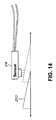
- the metal portion 110 can form, for example, a cam as shown in FIG. 3 , a metal portion 210 forming a wedge, or a metal portion 310 forming variable profile unit as shown in FIG. 14 and FIGS. 15 - 17 , respectively, can be used.
- the sensor 114 can detect a translational position of an object.
- the metal portion 210 forms a wedge, and the sensor 114 can determine an amount of metal material in the proximate location of the sensor 114.
- an amount of metal material increases.
- the amount of the metal material in the proximate location corresponds to the linear location of the metal portion 210.
- the amount of the metal material in the proximate location corresponds to the linear location of the metal portion 210 based on a monotonic function and such relationship can be stored, for example, in the memory 128 ( FIG. 11 ).
- the sensor 114 can determine a translational location of the metal portion 210.
- the sensor 114 can detect an amount of rotation of the metal portion 310.
- the metal portion 310 forms a variable profile unit, and the sensor 114 can determine an amount of metal material in the proximate location of the sensor 114.
- the metal portion 310 includes a thin portion 134 with a thickness of t2 and a thick portion 136 with a thickness of t1.
- the thickness t1 is greater than the thickness t2.
- FIGS. 16 and 17 For example, as the metal portion 310 is rotated, an amount of metal material in the proximate location of the sensor 114 increases as shown in FIGS. 16 and 17 .
- the thin portion 134 is facing the sensor 114
- the thick portion 136 is facing the sensor 114.
- the amount of the metal material in the proximate location corresponds to the rotation of the metal portion 210 based on a function and such relationship can be stored, for example, in the memory 128 ( FIG. 11 ).
- the sensor 114 can determine a rotation of the metal portion 210.
- aspects and implementations of the present disclosure may be useful for analysis of a variety of actions, activities, events, and phenomena.
- embodiments may be used to analyze any rotation motion. Such information may be used to detect or predict activity that approaches the known limits of a system or device to avoid extension beyond said limits. Such information may also be used to determine appropriate action in response to adjust at least one of the factors contributing to rotational action.
- embodiments may be used to collect information about activity and environment during a gait cycle. For example, the rotation of portions of a leg, knee, arm, elbow, or other articulated member may be sensed and utilized in a system or device to track, react to, or respond to such readings. Responses may include the application of settings in a prosthetic knee to facilitate improved mobility of a user. Other joints and parts of the body may be benefited by embodiments of the present disclosure.
- DSP digital signal processor
- ASIC application specific integrated circuit
- FPGA field programmable gate array
- a general purpose processor may be a microprocessor, but in the alternative, the processor may be any conventional processor, controller, microcontroller, or state machine.
- a processor may also be implemented as a combination of computing devices, e.g., a combination of a DSP and a microprocessor, a plurality of microprocessors, one or more microprocessors in conjunction with a DSP core, or any other such configuration.
- a software module may reside in RAM memory, flash memory, ROM memory, EPROM memory, EEPROM memory, registers, hard disk, a removable disk, a CD-ROM, or any other form of storage medium known in the art.
- An exemplary storage medium is coupled to the processor such that the processor can read information from, and write information to, the storage medium.
- the storage medium may be integral to the processor.
- the processor and the storage medium may reside in an Application Specific Integrated Circuit (ASIC).
- the ASIC may reside in a wireless modem.
- the processor and the storage medium may reside as discrete components in the wireless modem.
Landscapes
- Health & Medical Sciences (AREA)
- Transplantation (AREA)
- Heart & Thoracic Surgery (AREA)
- Vascular Medicine (AREA)
- Oral & Maxillofacial Surgery (AREA)
- Veterinary Medicine (AREA)
- Engineering & Computer Science (AREA)
- Biomedical Technology (AREA)
- Public Health (AREA)
- Cardiology (AREA)
- Life Sciences & Earth Sciences (AREA)
- Animal Behavior & Ethology (AREA)
- General Health & Medical Sciences (AREA)
- Physics & Mathematics (AREA)
- General Physics & Mathematics (AREA)
- Orthopedic Medicine & Surgery (AREA)
- Prostheses (AREA)
- Measurement Of Length, Angles, Or The Like Using Electric Or Magnetic Means (AREA)
Claims (12)
- Capteur (130) destiné à une articulation artificielle (102), le capteur (130) comprenant :- un élément rotatif (106) ; et- un matériau métallique (110) relié à l'élément rotatif (106) ;
le capteur (130) étant caractérisé par :- un capteur de proximité inductif (114) configuré pour détecter une quantité du matériau métallique (110) à un emplacement proche du capteur de proximité inductif (114), et pour générer une sortie qui correspond à un angle de l'élément rotatif (106) sur la base de la quantité de matériau métallique (110) à l'emplacement proche. - Capteur (130) selon la revendication 1, dans lequel la quantité de matériau métallique (110) à l'emplacement proche correspond à l'angle de l'élément rotatif (106) sur la base d'une fonction monotone.
- Capteur (130) selon la revendication 1, dans lequel l'élément rotatif (106) comprend une came, et dans lequel une rotation de l'élément rotatif (106) augmente ou réduit un espace (132) entre la came et le capteur de proximité inductif (114) afin de faire varier la quantité de matériau métallique (110) à l'emplacement proche.
- Capteur (130) selon la revendication 1, dans lequel l'élément rotatif (106) comprend une unité à profil variable, une rotation de l'élément rotatif (106) augmentant ou réduisant un espace entre l'unité à profil variable et le capteur de proximité inductif (114) de façon à faire varier la quantité de matériau métallique (110) à l'emplacement proche.
- Capteur (130) selon la revendication 1, dans lequel le matériau métallique (110) comprend un matériau métallique non ferreux.
- Capteur (130) selon la revendication 1, dans lequel l'élément rotatif (106) fait partie d'une prothèse de jambe.
- Capteur (130) selon la revendication 1, dans lequel l'élément rotatif (106) fait partie d'une prothèse de cheville.
- Capteur (130) selon la revendication 1, dans lequel l'emplacement proche est une forme sphérique basée sur un emplacement du capteur de proximité inductif (114).
- Procédé de détermination d'un angle d'un élément rotatif (106) au sein d'une prothèse d'articulation (102), le procédé comprenant :- la détection, à l'aide du capteur de proximité inductif (114) selon l'une quelconque des revendications 1 à 8, d'une quantité de matériau métallique (110) à un emplacement proche ; et- la génération, à l'aide du capteur de proximité inductif (114), d'une sortie qui correspond à un angle de l'élément rotatif (106) sur la base de la quantité de matériau métallique (110) à l'emplacement proche.
- Procédé selon la revendication 9, dans lequel la quantité de matériau métallique (110) à l'emplacement proche correspond à l'angle de l'élément rotatif (106) sur la base d'une fonction monotone.
- Procédé selon la revendication 9, qui comprend en outre la variation de la quantité de matériau métallique (110) à l'emplacement proche en faisant tourner l'élément rotatif (106) afin d'augmenter ou de réduire un espace entre une came de l'élément rotatif (106) et le capteur de proximité inductif (114).
- Procédé selon la revendication 9, qui comprend en outre la variation de la quantité de matériau métallique (110) à l'emplacement proche en faisant tourner l'élément rotatif (106) afin d'augmenter ou de réduire un espace entre une unité à profil variable de l'élément rotatif (106) et le capteur de proximité inductif (114).
Applications Claiming Priority (2)
| Application Number | Priority Date | Filing Date | Title |
|---|---|---|---|
| US30436810P | 2010-02-12 | 2010-02-12 | |
| PCT/US2011/022753 WO2011100118A2 (fr) | 2010-02-12 | 2011-01-27 | Dispositif et procédé de mesure d'angle |
Publications (3)
| Publication Number | Publication Date |
|---|---|
| EP2534450A2 EP2534450A2 (fr) | 2012-12-19 |
| EP2534450A4 EP2534450A4 (fr) | 2013-08-07 |
| EP2534450B1 true EP2534450B1 (fr) | 2016-04-27 |
Family
ID=44368378
Family Applications (1)
| Application Number | Title | Priority Date | Filing Date |
|---|---|---|---|
| EP11742614.8A Active EP2534450B1 (fr) | 2010-02-12 | 2011-01-27 | Dispositif et procédé de mesure d'angle |
Country Status (4)
| Country | Link |
|---|---|
| US (1) | US8717041B2 (fr) |
| EP (1) | EP2534450B1 (fr) |
| CA (1) | CA2789594A1 (fr) |
| WO (1) | WO2011100118A2 (fr) |
Families Citing this family (16)
| Publication number | Priority date | Publication date | Assignee | Title |
|---|---|---|---|---|
| US7815689B2 (en) | 2003-11-18 | 2010-10-19 | Victhom Human Bionics Inc. | Instrumented prosthetic foot |
| US7637959B2 (en) | 2004-02-12 | 2009-12-29 | össur hf | Systems and methods for adjusting the angle of a prosthetic ankle based on a measured surface angle |
| CA2592042C (fr) | 2004-12-22 | 2014-12-16 | Oessur Hf | Systemes et procedes de traitement du mouvement de membre |
| US9078773B2 (en) | 2007-09-19 | 2015-07-14 | Ability Dynamics Llc | Prosthetic foot |
| US12011373B2 (en) | 2007-09-19 | 2024-06-18 | Proteor USA, LLC | Mounting bracket for connecting a prosthetic limb to a prosthetic foot |
| US11020248B2 (en) | 2007-09-19 | 2021-06-01 | Proteor USA, LLC | Vacuum system for a prosthetic foot |
| US10405998B2 (en) | 2007-09-19 | 2019-09-10 | Ability Dynamics Llc | Mounting bracket for connecting a prosthetic limb to a prosthetic foot |
| EP2621414B1 (fr) | 2010-09-29 | 2019-03-13 | Össur HF | Dispositifs prosthétiques et orthétiques et procédés et systèmes pour commander ceux-ci |
| US9060884B2 (en) | 2011-05-03 | 2015-06-23 | Victhom Human Bionics Inc. | Impedance simulating motion controller for orthotic and prosthetic applications |
| US9561118B2 (en) | 2013-02-26 | 2017-02-07 | össur hf | Prosthetic foot with enhanced stability and elastic energy return |
| US9028557B2 (en) | 2013-03-14 | 2015-05-12 | Freedom Innovations, Llc | Prosthetic with voice coil valve |
| US12144748B2 (en) | 2013-08-27 | 2024-11-19 | Proteor USA, LLC | Microprocessor controlled prosthetic ankle system for footwear and terrain adaptation |
| US9763809B2 (en) | 2013-08-27 | 2017-09-19 | Freedom Innovations, Llc | Microprocessor controlled prosthetic ankle system for footwear and terrain adaptation |
| US10405999B2 (en) | 2014-02-18 | 2019-09-10 | Össur Iceland Ehf | Prosthetic joint with cam locking mechanism |
| EP3244841A4 (fr) | 2015-01-15 | 2018-09-12 | Ability Dynamics, LLC | Pied prothétique |
| US10030963B2 (en) | 2015-10-01 | 2018-07-24 | Raytheon Company | Multidimensional angle determination using fine position sensors |
Family Cites Families (22)
| Publication number | Priority date | Publication date | Assignee | Title |
|---|---|---|---|---|
| US5133773A (en) * | 1988-03-25 | 1992-07-28 | Kabushiki Kaisha Kobe Seiko Sho | Teaching playback swing-phase-controlled above-knee prosthesis |
| JP3244715B2 (ja) * | 1991-03-15 | 2002-01-07 | ヤマハ発動機株式会社 | エンジンの気筒判別センサ配置構造 |
| US5383939A (en) * | 1991-12-05 | 1995-01-24 | James; Kelvin B. | System for controlling artificial knee joint action in an above knee prosthesis |
| US6113642A (en) | 1996-06-27 | 2000-09-05 | Mauch, Inc. | Computer controlled hydraulic resistance device for a prosthesis and other apparatus |
| US5888212A (en) * | 1997-06-26 | 1999-03-30 | Mauch, Inc. | Computer controlled hydraulic resistance device for a prosthesis and other apparatus |
| GB9813904D0 (en) * | 1997-08-15 | 1998-08-26 | Blatchford & Sons Ltd | A lower limb prosthesis |
| GB2367753B (en) | 1997-08-15 | 2002-05-29 | Blatchford & Sons Ltd | A lower limb prosthesis |
| DE19754690A1 (de) * | 1997-12-10 | 1999-07-01 | Biedermann Motech Gmbh | Beinprothese mit einem künstlichen Kniegelenk mit einer Regeleinrichtung |
| GB9804611D0 (en) * | 1998-03-04 | 1998-04-29 | Blatchford & Sons Ltd | Lower limb prosthesis and control unit |
| DE19859931A1 (de) * | 1998-12-24 | 2000-07-06 | Biedermann Motech Gmbh | Beinprothese mit einem künstlichen Kniegelenk und Verfahren zur Steuerung einer Beinprothese |
| DE60112403T2 (de) * | 2000-01-20 | 2006-06-01 | Massachusetts Institute Of Technology, Cambridge | Elektronisch gesteuerte kniegelenkprothese |
| WO2001072245A2 (fr) * | 2000-03-29 | 2001-10-04 | Massachusetts Institute Of Technology | Prothese de genou adaptable a la vitesse et adaptable au patient |
| FR2808597B1 (fr) * | 2000-05-02 | 2002-07-12 | Schneider Electric Ind Sa | Detecteur inductif ou capacitif |
| US6673117B1 (en) * | 2000-11-30 | 2004-01-06 | Adam Soss | Single axis knee joint assembly |
| US7833287B2 (en) * | 2001-06-29 | 2010-11-16 | The Ohio Willow Wood Company | Adjustable multi-axis prosthetic ankle and method of use thereof |
| DE10214357A1 (de) * | 2002-03-28 | 2003-10-16 | Bock Healthcare Gmbh | Prothesen-Kniegelenk mit einem hydraulischen Dämpfungszylinder |
| JP4145139B2 (ja) * | 2002-12-26 | 2008-09-03 | 本田技研工業株式会社 | 変速機のギアポジション検知装置の配置構造 |
| US7163038B2 (en) * | 2004-03-01 | 2007-01-16 | Globe Machine Manufacturing Company | Systems and methods for end squaring and dividing elongated materials |
| CA2592042C (fr) * | 2004-12-22 | 2014-12-16 | Oessur Hf | Systemes et procedes de traitement du mouvement de membre |
| US8888864B2 (en) * | 2005-03-29 | 2014-11-18 | Motion Control | Energy storing foot plate |
| CA2611492C (fr) * | 2005-06-10 | 2014-05-13 | The Ohio Willow Wood Company | Dispositif prothetique dans lequel est utilisee une pompe a vide electrique |
| JP5164337B2 (ja) * | 2006-04-18 | 2013-03-21 | ヤマハ発動機株式会社 | 自動変速制御装置および鞍乗型車両 |
-
2011
- 2011-01-27 EP EP11742614.8A patent/EP2534450B1/fr active Active
- 2011-01-27 WO PCT/US2011/022753 patent/WO2011100118A2/fr not_active Ceased
- 2011-01-27 CA CA2789594A patent/CA2789594A1/fr not_active Abandoned
- 2011-01-27 US US13/015,442 patent/US8717041B2/en active Active
Also Published As
| Publication number | Publication date |
|---|---|
| WO2011100118A3 (fr) | 2011-10-27 |
| EP2534450A4 (fr) | 2013-08-07 |
| EP2534450A2 (fr) | 2012-12-19 |
| US8717041B2 (en) | 2014-05-06 |
| US20110199101A1 (en) | 2011-08-18 |
| WO2011100118A2 (fr) | 2011-08-18 |
| CA2789594A1 (fr) | 2011-08-18 |
Similar Documents
| Publication | Publication Date | Title |
|---|---|---|
| EP2534450B1 (fr) | Dispositif et procédé de mesure d'angle | |
| US10485682B2 (en) | Controlling torque in a prosthesis or orthosis based on a deflection of series elastic element | |
| CN105517511B (zh) | 用于控制人造矫形器或假肢膝关节的方法 | |
| EP2534458B1 (fr) | CAPTEUR DE CHARGE ET DE MOMENT COMPACT ET Robuste | |
| KR102184869B1 (ko) | 의수 시스템 | |
| US10369070B2 (en) | Motion assistive apparatus and method of controlling the same | |
| US9183346B2 (en) | Robotic appendages | |
| Furusho et al. | Development of shear type compact MR brake for the intelligent ankle-foot orthosis and its control; research and development in NEDO for practical application of human support robot | |
| CN104684509B (zh) | 带动力的下肢矫形器及其操作方法 | |
| US11779475B2 (en) | Torque measuring spring for a prosthetic drive | |
| Veneva et al. | Adaptive system for control of active ankle-foot orthosis and gait analysis | |
| CN107627325A (zh) | 一种工业机器人定位检测装置 | |
| Mueller et al. | A mobile motion analysis system using inertial sensors for analysis of lower limb prosthetics | |
| Chirakanphaisarn | Measurement and analysis system of the knee joint motion in gait evaluation for rehabilitation medicine | |
| Thomas et al. | Inertial thigh angle sensing for a semi-active knee prosthesis | |
| CN221998107U (zh) | 一种假肢 | |
| Meekeaw et al. | Development of a Below-Knee Prosthetic Foot with Automatic Angle Adjustment Mechanism | |
| KR20140004913A (ko) | 관절 각도 측정 장치 및 측정 방법 |
Legal Events
| Date | Code | Title | Description |
|---|---|---|---|
| PUAI | Public reference made under article 153(3) epc to a published international application that has entered the european phase |
Free format text: ORIGINAL CODE: 0009012 |
|
| 17P | Request for examination filed |
Effective date: 20120824 |
|
| AK | Designated contracting states |
Kind code of ref document: A2 Designated state(s): AL AT BE BG CH CY CZ DE DK EE ES FI FR GB GR HR HU IE IS IT LI LT LU LV MC MK MT NL NO PL PT RO RS SE SI SK SM TR |
|
| DAX | Request for extension of the european patent (deleted) | ||
| A4 | Supplementary search report drawn up and despatched |
Effective date: 20130705 |
|
| RIC1 | Information provided on ipc code assigned before grant |
Ipc: A61F 2/64 20060101ALI20130701BHEP Ipc: G01D 5/20 20060101AFI20130701BHEP Ipc: A61F 2/70 20060101ALI20130701BHEP Ipc: A61F 2/76 20060101ALI20130701BHEP Ipc: A61F 2/68 20060101ALI20130701BHEP Ipc: A61F 2/66 20060101ALI20130701BHEP |
|
| 17Q | First examination report despatched |
Effective date: 20140930 |
|
| GRAP | Despatch of communication of intention to grant a patent |
Free format text: ORIGINAL CODE: EPIDOSNIGR1 |
|
| INTG | Intention to grant announced |
Effective date: 20151102 |
|
| GRAS | Grant fee paid |
Free format text: ORIGINAL CODE: EPIDOSNIGR3 |
|
| GRAA | (expected) grant |
Free format text: ORIGINAL CODE: 0009210 |
|
| AK | Designated contracting states |
Kind code of ref document: B1 Designated state(s): AL AT BE BG CH CY CZ DE DK EE ES FI FR GB GR HR HU IE IS IT LI LT LU LV MC MK MT NL NO PL PT RO RS SE SI SK SM TR |
|
| REG | Reference to a national code |
Ref country code: GB Ref legal event code: FG4D |
|
| REG | Reference to a national code |
Ref country code: CH Ref legal event code: EP |
|
| REG | Reference to a national code |
Ref country code: AT Ref legal event code: REF Ref document number: 795310 Country of ref document: AT Kind code of ref document: T Effective date: 20160515 |
|
| REG | Reference to a national code |
Ref country code: IE Ref legal event code: FG4D |
|
| REG | Reference to a national code |
Ref country code: DE Ref legal event code: R096 Ref document number: 602011025931 Country of ref document: DE |
|
| REG | Reference to a national code |
Ref country code: LT Ref legal event code: MG4D |
|
| REG | Reference to a national code |
Ref country code: NL Ref legal event code: MP Effective date: 20160427 |
|
| REG | Reference to a national code |
Ref country code: DE Ref legal event code: R082 Ref document number: 602011025931 Country of ref document: DE Representative=s name: HERNANDEZ, YORCK, DIPL.-ING., DE Ref country code: DE Ref legal event code: R082 Ref document number: 602011025931 Country of ref document: DE |
|
| REG | Reference to a national code |
Ref country code: AT Ref legal event code: MK05 Ref document number: 795310 Country of ref document: AT Kind code of ref document: T Effective date: 20160427 |
|
| PG25 | Lapsed in a contracting state [announced via postgrant information from national office to epo] |
Ref country code: NL Free format text: LAPSE BECAUSE OF FAILURE TO SUBMIT A TRANSLATION OF THE DESCRIPTION OR TO PAY THE FEE WITHIN THE PRESCRIBED TIME-LIMIT Effective date: 20160427 |
|
| PG25 | Lapsed in a contracting state [announced via postgrant information from national office to epo] |
Ref country code: LT Free format text: LAPSE BECAUSE OF FAILURE TO SUBMIT A TRANSLATION OF THE DESCRIPTION OR TO PAY THE FEE WITHIN THE PRESCRIBED TIME-LIMIT Effective date: 20160427 Ref country code: PL Free format text: LAPSE BECAUSE OF FAILURE TO SUBMIT A TRANSLATION OF THE DESCRIPTION OR TO PAY THE FEE WITHIN THE PRESCRIBED TIME-LIMIT Effective date: 20160427 Ref country code: NO Free format text: LAPSE BECAUSE OF FAILURE TO SUBMIT A TRANSLATION OF THE DESCRIPTION OR TO PAY THE FEE WITHIN THE PRESCRIBED TIME-LIMIT Effective date: 20160727 Ref country code: FI Free format text: LAPSE BECAUSE OF FAILURE TO SUBMIT A TRANSLATION OF THE DESCRIPTION OR TO PAY THE FEE WITHIN THE PRESCRIBED TIME-LIMIT Effective date: 20160427 |
|
| PG25 | Lapsed in a contracting state [announced via postgrant information from national office to epo] |
Ref country code: GR Free format text: LAPSE BECAUSE OF FAILURE TO SUBMIT A TRANSLATION OF THE DESCRIPTION OR TO PAY THE FEE WITHIN THE PRESCRIBED TIME-LIMIT Effective date: 20160728 Ref country code: PT Free format text: LAPSE BECAUSE OF FAILURE TO SUBMIT A TRANSLATION OF THE DESCRIPTION OR TO PAY THE FEE WITHIN THE PRESCRIBED TIME-LIMIT Effective date: 20160829 Ref country code: SE Free format text: LAPSE BECAUSE OF FAILURE TO SUBMIT A TRANSLATION OF THE DESCRIPTION OR TO PAY THE FEE WITHIN THE PRESCRIBED TIME-LIMIT Effective date: 20160427 Ref country code: HR Free format text: LAPSE BECAUSE OF FAILURE TO SUBMIT A TRANSLATION OF THE DESCRIPTION OR TO PAY THE FEE WITHIN THE PRESCRIBED TIME-LIMIT Effective date: 20160427 Ref country code: RS Free format text: LAPSE BECAUSE OF FAILURE TO SUBMIT A TRANSLATION OF THE DESCRIPTION OR TO PAY THE FEE WITHIN THE PRESCRIBED TIME-LIMIT Effective date: 20160427 Ref country code: ES Free format text: LAPSE BECAUSE OF FAILURE TO SUBMIT A TRANSLATION OF THE DESCRIPTION OR TO PAY THE FEE WITHIN THE PRESCRIBED TIME-LIMIT Effective date: 20160427 Ref country code: LV Free format text: LAPSE BECAUSE OF FAILURE TO SUBMIT A TRANSLATION OF THE DESCRIPTION OR TO PAY THE FEE WITHIN THE PRESCRIBED TIME-LIMIT Effective date: 20160427 Ref country code: AT Free format text: LAPSE BECAUSE OF FAILURE TO SUBMIT A TRANSLATION OF THE DESCRIPTION OR TO PAY THE FEE WITHIN THE PRESCRIBED TIME-LIMIT Effective date: 20160427 |
|
| PG25 | Lapsed in a contracting state [announced via postgrant information from national office to epo] |
Ref country code: IT Free format text: LAPSE BECAUSE OF FAILURE TO SUBMIT A TRANSLATION OF THE DESCRIPTION OR TO PAY THE FEE WITHIN THE PRESCRIBED TIME-LIMIT Effective date: 20160427 Ref country code: BE Free format text: LAPSE BECAUSE OF FAILURE TO SUBMIT A TRANSLATION OF THE DESCRIPTION OR TO PAY THE FEE WITHIN THE PRESCRIBED TIME-LIMIT Effective date: 20160427 |
|
| REG | Reference to a national code |
Ref country code: DE Ref legal event code: R097 Ref document number: 602011025931 Country of ref document: DE |
|
| PG25 | Lapsed in a contracting state [announced via postgrant information from national office to epo] |
Ref country code: EE Free format text: LAPSE BECAUSE OF FAILURE TO SUBMIT A TRANSLATION OF THE DESCRIPTION OR TO PAY THE FEE WITHIN THE PRESCRIBED TIME-LIMIT Effective date: 20160427 Ref country code: SK Free format text: LAPSE BECAUSE OF FAILURE TO SUBMIT A TRANSLATION OF THE DESCRIPTION OR TO PAY THE FEE WITHIN THE PRESCRIBED TIME-LIMIT Effective date: 20160427 Ref country code: CZ Free format text: LAPSE BECAUSE OF FAILURE TO SUBMIT A TRANSLATION OF THE DESCRIPTION OR TO PAY THE FEE WITHIN THE PRESCRIBED TIME-LIMIT Effective date: 20160427 Ref country code: DK Free format text: LAPSE BECAUSE OF FAILURE TO SUBMIT A TRANSLATION OF THE DESCRIPTION OR TO PAY THE FEE WITHIN THE PRESCRIBED TIME-LIMIT Effective date: 20160427 Ref country code: RO Free format text: LAPSE BECAUSE OF FAILURE TO SUBMIT A TRANSLATION OF THE DESCRIPTION OR TO PAY THE FEE WITHIN THE PRESCRIBED TIME-LIMIT Effective date: 20160427 |
|
| PG25 | Lapsed in a contracting state [announced via postgrant information from national office to epo] |
Ref country code: SM Free format text: LAPSE BECAUSE OF FAILURE TO SUBMIT A TRANSLATION OF THE DESCRIPTION OR TO PAY THE FEE WITHIN THE PRESCRIBED TIME-LIMIT Effective date: 20160427 |
|
| PLBE | No opposition filed within time limit |
Free format text: ORIGINAL CODE: 0009261 |
|
| STAA | Information on the status of an ep patent application or granted ep patent |
Free format text: STATUS: NO OPPOSITION FILED WITHIN TIME LIMIT |
|
| 26N | No opposition filed |
Effective date: 20170130 |
|
| PG25 | Lapsed in a contracting state [announced via postgrant information from national office to epo] |
Ref country code: SI Free format text: LAPSE BECAUSE OF FAILURE TO SUBMIT A TRANSLATION OF THE DESCRIPTION OR TO PAY THE FEE WITHIN THE PRESCRIBED TIME-LIMIT Effective date: 20160427 |
|
| REG | Reference to a national code |
Ref country code: CH Ref legal event code: PL |
|
| GBPC | Gb: european patent ceased through non-payment of renewal fee |
Effective date: 20170127 |
|
| PG25 | Lapsed in a contracting state [announced via postgrant information from national office to epo] |
Ref country code: MC Free format text: LAPSE BECAUSE OF FAILURE TO SUBMIT A TRANSLATION OF THE DESCRIPTION OR TO PAY THE FEE WITHIN THE PRESCRIBED TIME-LIMIT Effective date: 20160427 |
|
| REG | Reference to a national code |
Ref country code: FR Ref legal event code: ST Effective date: 20170929 |
|
| PG25 | Lapsed in a contracting state [announced via postgrant information from national office to epo] |
Ref country code: FR Free format text: LAPSE BECAUSE OF NON-PAYMENT OF DUE FEES Effective date: 20170131 Ref country code: LI Free format text: LAPSE BECAUSE OF NON-PAYMENT OF DUE FEES Effective date: 20170131 Ref country code: CH Free format text: LAPSE BECAUSE OF NON-PAYMENT OF DUE FEES Effective date: 20170131 |
|
| REG | Reference to a national code |
Ref country code: IE Ref legal event code: MM4A |
|
| PG25 | Lapsed in a contracting state [announced via postgrant information from national office to epo] |
Ref country code: LU Free format text: LAPSE BECAUSE OF NON-PAYMENT OF DUE FEES Effective date: 20170127 Ref country code: GB Free format text: LAPSE BECAUSE OF NON-PAYMENT OF DUE FEES Effective date: 20170127 |
|
| PG25 | Lapsed in a contracting state [announced via postgrant information from national office to epo] |
Ref country code: IE Free format text: LAPSE BECAUSE OF NON-PAYMENT OF DUE FEES Effective date: 20170127 |
|
| PG25 | Lapsed in a contracting state [announced via postgrant information from national office to epo] |
Ref country code: MT Free format text: LAPSE BECAUSE OF NON-PAYMENT OF DUE FEES Effective date: 20170127 |
|
| PG25 | Lapsed in a contracting state [announced via postgrant information from national office to epo] |
Ref country code: AL Free format text: LAPSE BECAUSE OF FAILURE TO SUBMIT A TRANSLATION OF THE DESCRIPTION OR TO PAY THE FEE WITHIN THE PRESCRIBED TIME-LIMIT Effective date: 20160427 |
|
| PG25 | Lapsed in a contracting state [announced via postgrant information from national office to epo] |
Ref country code: HU Free format text: LAPSE BECAUSE OF FAILURE TO SUBMIT A TRANSLATION OF THE DESCRIPTION OR TO PAY THE FEE WITHIN THE PRESCRIBED TIME-LIMIT; INVALID AB INITIO Effective date: 20110127 |
|
| PG25 | Lapsed in a contracting state [announced via postgrant information from national office to epo] |
Ref country code: BG Free format text: LAPSE BECAUSE OF FAILURE TO SUBMIT A TRANSLATION OF THE DESCRIPTION OR TO PAY THE FEE WITHIN THE PRESCRIBED TIME-LIMIT Effective date: 20160427 |
|
| PG25 | Lapsed in a contracting state [announced via postgrant information from national office to epo] |
Ref country code: CY Free format text: LAPSE BECAUSE OF NON-PAYMENT OF DUE FEES Effective date: 20160427 |
|
| PG25 | Lapsed in a contracting state [announced via postgrant information from national office to epo] |
Ref country code: MK Free format text: LAPSE BECAUSE OF FAILURE TO SUBMIT A TRANSLATION OF THE DESCRIPTION OR TO PAY THE FEE WITHIN THE PRESCRIBED TIME-LIMIT Effective date: 20160427 |
|
| PG25 | Lapsed in a contracting state [announced via postgrant information from national office to epo] |
Ref country code: TR Free format text: LAPSE BECAUSE OF FAILURE TO SUBMIT A TRANSLATION OF THE DESCRIPTION OR TO PAY THE FEE WITHIN THE PRESCRIBED TIME-LIMIT Effective date: 20160427 |
|
| PG25 | Lapsed in a contracting state [announced via postgrant information from national office to epo] |
Ref country code: IS Free format text: LAPSE BECAUSE OF FAILURE TO SUBMIT A TRANSLATION OF THE DESCRIPTION OR TO PAY THE FEE WITHIN THE PRESCRIBED TIME-LIMIT Effective date: 20160827 |
|
| REG | Reference to a national code |
Ref country code: DE Ref legal event code: R081 Ref document number: 602011025931 Country of ref document: DE Owner name: PROTEOR USA, LLC, TEMPE, US Free format text: FORMER OWNER: FREEDOM INNOVATIONS LLC, IRVINE, CALIF., US Ref country code: DE Ref legal event code: R082 Ref document number: 602011025931 Country of ref document: DE Representative=s name: HERNANDEZ, YORCK, DIPL.-ING., DE |
|
| P01 | Opt-out of the competence of the unified patent court (upc) registered |
Effective date: 20230630 |
|
| PGFP | Annual fee paid to national office [announced via postgrant information from national office to epo] |
Ref country code: DE Payment date: 20251203 Year of fee payment: 16 |