EP2534561B1 - Computertastatur mit integrierter elektrodenanordnung - Google Patents
Computertastatur mit integrierter elektrodenanordnung Download PDFInfo
- Publication number
- EP2534561B1 EP2534561B1 EP11716367.5A EP11716367A EP2534561B1 EP 2534561 B1 EP2534561 B1 EP 2534561B1 EP 11716367 A EP11716367 A EP 11716367A EP 2534561 B1 EP2534561 B1 EP 2534561B1
- Authority
- EP
- European Patent Office
- Prior art keywords
- electrode
- input device
- keyboard
- hand
- detection
- Prior art date
- Legal status (The legal status is an assumption and is not a legal conclusion. Google has not performed a legal analysis and makes no representation as to the accuracy of the status listed.)
- Active
Links
Images





Classifications
-
- G—PHYSICS
- G06—COMPUTING OR CALCULATING; COUNTING
- G06F—ELECTRIC DIGITAL DATA PROCESSING
- G06F3/00—Input arrangements for transferring data to be processed into a form capable of being handled by the computer; Output arrangements for transferring data from processing unit to output unit, e.g. interface arrangements
- G06F3/01—Input arrangements or combined input and output arrangements for interaction between user and computer
- G06F3/03—Arrangements for converting the position or the displacement of a member into a coded form
- G06F3/041—Digitisers, e.g. for touch screens or touch pads, characterised by the transducing means
- G06F3/044—Digitisers, e.g. for touch screens or touch pads, characterised by the transducing means by capacitive means
-
- G—PHYSICS
- G06—COMPUTING OR CALCULATING; COUNTING
- G06F—ELECTRIC DIGITAL DATA PROCESSING
- G06F3/00—Input arrangements for transferring data to be processed into a form capable of being handled by the computer; Output arrangements for transferring data from processing unit to output unit, e.g. interface arrangements
- G06F3/01—Input arrangements or combined input and output arrangements for interaction between user and computer
- G06F3/048—Interaction techniques based on graphical user interfaces [GUI]
- G06F3/0487—Interaction techniques based on graphical user interfaces [GUI] using specific features provided by the input device, e.g. functions controlled by the rotation of a mouse with dual sensing arrangements, or of the nature of the input device, e.g. tap gestures based on pressure sensed by a digitiser
- G06F3/0488—Interaction techniques based on graphical user interfaces [GUI] using specific features provided by the input device, e.g. functions controlled by the rotation of a mouse with dual sensing arrangements, or of the nature of the input device, e.g. tap gestures based on pressure sensed by a digitiser using a touch-screen or digitiser, e.g. input of commands through traced gestures
- G06F3/04883—Interaction techniques based on graphical user interfaces [GUI] using specific features provided by the input device, e.g. functions controlled by the rotation of a mouse with dual sensing arrangements, or of the nature of the input device, e.g. tap gestures based on pressure sensed by a digitiser using a touch-screen or digitiser, e.g. input of commands through traced gestures for inputting data by handwriting, e.g. gesture or text
-
- G—PHYSICS
- G06—COMPUTING OR CALCULATING; COUNTING
- G06F—ELECTRIC DIGITAL DATA PROCESSING
- G06F3/00—Input arrangements for transferring data to be processed into a form capable of being handled by the computer; Output arrangements for transferring data from processing unit to output unit, e.g. interface arrangements
- G06F3/01—Input arrangements or combined input and output arrangements for interaction between user and computer
- G06F3/017—Gesture based interaction, e.g. based on a set of recognized hand gestures
-
- G—PHYSICS
- G06—COMPUTING OR CALCULATING; COUNTING
- G06F—ELECTRIC DIGITAL DATA PROCESSING
- G06F3/00—Input arrangements for transferring data to be processed into a form capable of being handled by the computer; Output arrangements for transferring data from processing unit to output unit, e.g. interface arrangements
- G06F3/01—Input arrangements or combined input and output arrangements for interaction between user and computer
- G06F3/03—Arrangements for converting the position or the displacement of a member into a coded form
- G06F3/041—Digitisers, e.g. for touch screens or touch pads, characterised by the transducing means
- G06F3/044—Digitisers, e.g. for touch screens or touch pads, characterised by the transducing means by capacitive means
- G06F3/0445—Digitisers, e.g. for touch screens or touch pads, characterised by the transducing means by capacitive means using two or more layers of sensing electrodes, e.g. using two layers of electrodes separated by a dielectric layer
-
- G—PHYSICS
- G06—COMPUTING OR CALCULATING; COUNTING
- G06F—ELECTRIC DIGITAL DATA PROCESSING
- G06F3/00—Input arrangements for transferring data to be processed into a form capable of being handled by the computer; Output arrangements for transferring data from processing unit to output unit, e.g. interface arrangements
- G06F3/01—Input arrangements or combined input and output arrangements for interaction between user and computer
- G06F3/048—Interaction techniques based on graphical user interfaces [GUI]
- G06F3/0487—Interaction techniques based on graphical user interfaces [GUI] using specific features provided by the input device, e.g. functions controlled by the rotation of a mouse with dual sensing arrangements, or of the nature of the input device, e.g. tap gestures based on pressure sensed by a digitiser
- G06F3/0488—Interaction techniques based on graphical user interfaces [GUI] using specific features provided by the input device, e.g. functions controlled by the rotation of a mouse with dual sensing arrangements, or of the nature of the input device, e.g. tap gestures based on pressure sensed by a digitiser using a touch-screen or digitiser, e.g. input of commands through traced gestures
Definitions
- the invention concerns an input device, in particular in the form of a computer keyboard, that includes a keyboard over which in a per se well-known way by manually pressing keys corresponding keyboard entries can be made.
- Such computer keyboards are widespread as independent peripheral devices or as integrated input system in case of portable computers, especially notebooks.
- a keyboard e.g. a computer mouse, a track ball, a graphic tablet or - especially for notebooks - a touch pad.
- a pointing device e.g. a computer mouse, a track ball, a graphic tablet or - especially for notebooks - a touch pad.
- cursor positions can be manually coordinated.
- the movements of a cursor correlate with a movement of the mouse, or a movement of a finger on the touch pad.
- Pointing equipment typically also includes additional keys or input elements with which determined operations can be carried out, e. g. a left, middle, and right mouse button for selecting elements of the user interface, a scroll wheel, a wheel button and/or additional keys alongside the mouse or a strip on a touch pad, in which a contact and movement of the finger entails a scrolling, as well as special functions provided in the corners of a touch pad.
- additional keys or input elements can be also configured by the user, e.g. special function calls of the operating system if pressing an additional mouse button or if touching a certain corner of the touch pad.
- US2006/0232567 A1 discloses an input device allowing proximity detection of touches based on capacitance measurements.
- the object of the invention is to create solutions in which for a user of a computer keyboard special operator benefits result as compared to conventional keyboard systems in association with a pointing device.
- a computer keyboard may comprise a keyboard that includes a multitude of manually operable keys, and in this keyboard an electrode arrangement is integrated, which is designed, sensed and evaluated via a driver circuit in such a manner that by means of this electrode arrangement the detection of the spatial position or movement of a finger or a hand in an area in front of the keyboard is effected by use of an electrical-field, and wherein by means of the driver, circuit system signals are provided that have an information content that correlates with position and/or movement of a finger or a hand of the user.
- a keyboard as an interface for gesture-like input operations and especially also to command the cursor in a precise and well coordinated way on a graphic user interface, and also to fulfill additional tasks, without having to remove the hands out of the space above the keyboard for using a pointing device.
- control functions by a corresponding driver which allow an intuitively particularly well manageable application of the technique according to the invention.
- the control program can be oriented in such a way that in this state the gesture-based cursor control function is provided and a gesture-like navigation without contact of the cursor on a display is made possible. As soon as one of the two hands contacts the keyboard again, this cursor control mode is finished.
- gestures by means of which special programme functions can be activated. For example it is possible to provide own input gestures for a certain activation of the gesture control. For example a movement of the palm of the hand in the fashion of a beckoning from an upper edge area of the keyboard can cause a pull down of the virtual touch pad over the number pad of the keyboard. When not using this feature, by moving the backs of the fingers towards the upper keyboard edge thus by waving aside, this virtual pad can again be pushed away.
- gestures can also illustrate functions of keys or other input elements that are typically applied on a pointing device, for example the click with the left/right mouse button by fast moving up and down a finger over the left/right input area of the keyboard or a scroll (scroll wheel) by slow movements with the whole hand into X or Y direction above the keyboard.
- a particularly intuitive extension of the range of functions of the display device with further important functions is possible, e. g. augmenting or diminishing a selected object or indicating range by a movement above the keyboard in Z direction.
- the keys or further input elements of a pointing device can also be applied partially or in their entirety on the keyboard, e.g. a touch-sensitive strip for scrolling or keys for the function of the mouse buttons.
- the keyboard is configured in such a way that the electrode arrangement includes a group of electrodes.
- This group of electrodes preferably includes an electrode subgroup that serves to detect signals indicative of the position.
- the electrode group preferably includes a main electrode serving for contact detection.
- This main electrode can be designed as a relatively extensive electrode and extend substantially over the total keyboard.
- This main electrode can be provided with openings, which for example allow the mechanical accessibility of the keys.
- the main electrode can be realized as a substantially flat metal layer.
- the main electrode can also be realized in interaction with other components of the keyboard. Especially it is possible to realize the main electrode by a metallic coating of the housing section below the keys of the keyboard, especially also by a metallic coating of the internal area of the keyboard housing. It is also possible to integrate at least some keys into the main electrode.
- the keys can be metallized for this purpose in the area of their upper side or back side. It is also possible to produce the keys in an electrically conductive material.
- the metallized, or electrically conductive keys do not have to be necessarily galvanically coupled with the main electrode. It is possible to realize between the main electrode and the keys a certain overlap and thus an electrical-field coupling, so that in the end the field generated by the main electrode can further diffuse over the conductive keys.
- the electrodes used as position detection electrodes can be arranged in the area of the number pad, or in the area typically used for the arrow keys.
- the size of this position detection electrodes can substantially correspond to the size of these keys.
- the position electrodes can be formed especially by these control keys. In this way it is advantageously possible to use the markings provided there anyway for navigation support for the touchless mouse control mode realizable according to the invention.
- the keyboard according to the invention can be formed in such a way that it performs a dynamic allocation of the single electrodes with determined functions. For example it is possible in a primary recognized approach of a hand or a finger to use an electrode group for the precise determination of the position, that makes possible a particularly good triangulation of the finger or hand position. Ideal are electrodes situated with respect to the current finger position in the area of a cone surface the vertically opposed angle of which is in the range 30 to 60°.
- the electrode arrangement and the respective driver circuit are configured in such a way that they can detect a state to be considered a touch of the keyboard, and corresponding system signals are generated. This contact can be detected on the basis of certain signal levels and/or certain dynamic characteristics.
- the keyboard according to the invention is preferably configured in such a way that a vertical projection of the observation area used for the position detection of a finger in the keyboard plane extends in a contact detection range. In this way it is possible at first to perform a cursor control without contact and to conclude this movement set by lowering and laying down the finger on the keyboard.
- the invention thus especially concerns a system, that makes possible both the detection of a finger movement preliminary to contacting a keyboard and the physical contacting of the keyboard itself.
- the system makes possible the processing of special gestures that besides a certain spatial course also contain contact phases or are initiated or concluded by them.
- the electrode arrangement is preferably configured in such a way that it includes several electrodes arranged in the edge zone of the keyboard, these electrodes arranged in the edge zone being used for generating the signals indicative of the finger position.
- the system signals generated by the driver circuit connected to the electrode arrangement are used according to the invention for the realization of a gesture-based control.
- the driver circuit can be formed in such a way that the system signals generated by it exist in a data or signal format usual for computer periphery systems. It is possible to undertake, already in the area of the driver circuit, a relatively extensive signal preprocessing, by which a certain attenuation, scaling and where applicable also certain effects like a ballistic effect are reached.
- the X, Y and preferably also Z axis information obtained according to the invention by means of an electrode arrangement can be processed by a corresponding background program in the actual computer system.
- the obtained signals can be evaluated also by a gesture detection program. Gesture interpretation and cursor control can be connected.
- the electrodes are grouped and arranged in such a way that one electrode subgroup primarily for detecting hand or finger movements of the right working hand and one primarily for detecting hand or finger movements of the left working hand are provided.
- the signals each time detected by both these electrode groups can be assigned each to a hand of the user.
- special statements can be made. For example a closing signal indicative for the conclusion of a gesture can be generated by touching a component of the keyboard.
- a closing signal for a gesture coordinated by the right hand is generated by a contact of the left hand with a keyboard component.
- the driver circuit attached to the electrode arrangement can be formed in such a way that the position detection is done by successively measuring the levels of the voltages which are present at the position detection electrodes. Moreover it is possible to detect the field bridging between the position detection electrodes or the field bridging between the position detection electrodes and the main electrode. This detection can take place especially by voltage or load measurement.
- the area serving for the spatial detection of the finger position or finger movement can be sized in such a way that it substantially corresponds to the range of motion of the finger in association with a light movement of the hand in the wrist.
- the observation area used for the finger position detection corresponds preferably more or less to a cube with an edge length from 8 to 14 cm.
- the position resolution is done preferably in the central area and in case of close approach to the keyboard with a greater precision than in the edge zone. It is possible, by a fast stirring movement of the forefinger or middle finger approached up to roughly 5 cm from the keyboard, to induce a cursor centering on the screen and then, by the further finger movement, to perform a corresponding movement of the cursor on the screen. It is possible to perform the cursor control in such a way that, for the cursor movement, finger movements are considered that are carried out in case of a certain Z distance value, thus a sufficiently narrow approach. Movements above a corresponding plane are then disregarded.
- Figure 1 shows a notebook computer with a flat display and a keyboard equipment.
- an electrode device is provided for detecting the position of the finger of a user relatively to the keyboard equipment, without the keyboard being touched.
- the notebook computer is configured in such a way that the progress of an application program used in association with it can be coordinated by the movement of a finger of the user relative to the keyboard.
- the electrode device includes several electrode sections provided in the area of the keyboard ELP, ELB that are connected to a sensor circuit, in which by that sensor circuit measuring signals are detected and processed, in which those measuring signals are influenced by the effect of the finger of the user on the electric-field properties of the environment of the respective electrode sections ELP, ELB.
- an electrode device for detecting the position of a finger of the user in an area in front of the flat display device.
- a contact sensor system for detecting a signal indicative of a contact with the keyboard or its surrounding area.
- a contact sensor system for detecting a signal indicative of a contact with the flat display device.
- the electrode system integrated into the portable computer it is possible to detect finger movements and approach states of the left and right hand without contact and to command with these detection results the progress of a user program.
- FIG 2a a conventional computer keyboard is illustrated, by means of which in a per se well-known way inputs into a corresponding computer can be done.
- Such keyboards are used predominantly in association with a computer mouse.
- this computer mouse it is possible to carry out a cursor movement correlating with the movement of the mouse.
- a notebook is illustrated that includes an integrated keyboard and a touch pad.
- the touch pad By means of the touch pad it is possible to induce cursor movements that correlate with the movement of the finger of a user on the touch pad.
- This solution is particularly used in notebooks, since no additional devices have to be carried around. Disadvantages of this alternative are a small active surface (for some tasks the operation is too sensitive); moreover space on the surface of the computer is necessary.
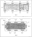
- FIG 3 shows in a highly simplified way a keyboard T configured according to the invention that includes several keys K.
- This keyboard in an area under the housing surface, is equipped with electrodes, in the following called gesticulation electrodes (outlined by broken lines).
- the contact detection electrode EL_B can be designed as a grate in the free space between the keys. Also in the other illustrations there is this graphic simplification.
- the number of the position detection electrodes EL_P can vary; when it is greater (e.g. 8, as illustrated in figure 3 ), the movements of both hands can be registered.
- the keys K have a possibly flat form, like the keys of notebook keyboards.
- the hand position over the coverage area can be translated directly into the screen-coordinates, for example: right lower area of the keyboard corresponds to the right lower area on the screen.
- the deflection of the hand from the center of the coverage area can command the direction and the speed of the mouse pointer movement on the screen, for example: hand over the center of the keyboard causes no movement of the cursor, hand over right lower area of the keyboard moves the cursor downwards to the right with maximum (preset) speed.
- the invention offers an improvement, on the one hand by the fact, that the space hitherto occupied by the touch pad can be used for the keyboard. Moreover it is possible to reproduce, based on the small "base keyboard” ( figure 4 ), the functionality of the full keyboard.
- the invention also allows a completely gesture controlled operation.
- An important point is that the invention can be used in connection with existing software applications, and by using the invention the user can pass more easily from the former standard operation towards gesture operation.
- the invention also offers the additional possibilities of the gesture control of existing system commands, e.g. a movement of the hand from top to bottom over the keyboard minimizes all the windows on the screen; the movement of the hand from the right to the left over the complete keyboard means "switch off computer".
- FIG 4 another variant of a computer keyboard - without number pad - is illustrated, which comprises, similarly to the keyboard according to figure 3 , position detection electrodes close to the border.
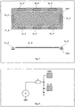
- Figure 5 shows an electrode arrangement with electrodes applied in 2 layers from both sides on an insulating layer (represented as a slice at the bottom of the illustration).
- the generator electrode GEN extends under all position detection electrodes EL_P as well as under the contact detection electrode EL_B.
- the electrodes are connected to the gesture electronics according to figure 6 .
- the generator electrode GEN is a frame under the position detection electrodes EL_P.
- the contact detection electrode EL_B is made in only one layer and can be realized e.g. as a grate between the keys or as a conductive foil with the openings for the key bars. Also the complete metallic coating of the keyboard can be used as EL_B.
- Such an electrode arrangement can be attached to the gesture electronics in various ways, as it is shown typically in the figures 6 , 8 , 9, and 10 .
- Figs. 6 and 10 show by way of example how the contact detection electrode can be connected to one of the entries of the gesture electronics. This entry does not have to be designed specially for this purpose.
- Figure 10 shows the connection possibility by means of a coupling capacitor CK to the "standard" gesture electronics.
- Figure 8 and figure 9 show this variant with the measurement of the capacitive load at the generator electrode. This can be done for the load C e.g. by measuring the voltage drop at a connection impedance Z connected between the generator G and the generator electrode EL_B (schematically as signal S). This method of detecting the contact can be advantageous as it can be realized with a minor expenditure of electrodes in certain applications.
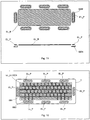
- FIG 11 an electrode configuration is illustrated in which all of the position detection electrodes EL_P are made as smaller units (tablets) together with the generator electrodes GEN.
- Switching areas are defined on the keyboard, starting from which the device is switched over into the mouse mode (or vice versa). These switching areas (example in figure 12 EB1 and EB2) can be defined best over the present electrodes. Their definition can apply for the left hand, for the right hand, or for both hands.
- a further embodiment of the invention as for the detection of clicks in the mouse mode consists in the fact that as soon as the input device is put into this mode, every key actuation at the keyboard is interpreted as a mouse click.
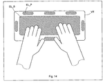
- FIG 14 Another field of application of the invention is illustrated in figure 14 .
- a device VT is shown that has no keys and tendentiously looks like an enlarged mouse pad.
- This device acts as keyboard and pointing device, which is used when using a computer.
- a virtual keyboard is visualized on the screen (similar to the number pad described before). It may include electrically inoperable keys for generating a tactile feedback. The keys however can also be completely omitted and optionally be printed on the area for orientation.
- the keyboard can appear as a guidance semitransparent over other applications on the screen or in a (dedicated) partition of the screen; the cursor control is done by gestures as described above.
- This field can be equipped with a slightly elastic coating. The definitive selection or actuation of a key is done only when exceeding a determined contact pressure or a determined dynamic profile.
Landscapes
- Engineering & Computer Science (AREA)
- General Engineering & Computer Science (AREA)
- Theoretical Computer Science (AREA)
- Human Computer Interaction (AREA)
- Physics & Mathematics (AREA)
- General Physics & Mathematics (AREA)
- Position Input By Displaying (AREA)
- User Interface Of Digital Computer (AREA)
Claims (15)
- Eingabevorrichtung, die aufweist:- eine Tastatur, die eine Vielzahl von manuell bedienbaren Tasten (K) umfasst, die weiterhin aufweist:- eine Elektrodenanordnung, die zumindest eine Generatorelektrode (GEN, EL_B) und eine Vielzahl von Detektionselektroden (EL_B, EL_P) aufweist, dadurch gekennzeichnet, dass- die Generatorelektrode (GEN) ein Ansteuersignal empfängt, das ein elektrisches Feld zwischen der Generatorelektrode (GEN) und den Detektionselektroden (EL_B, EL_P) erzeugt;- eine Auswerteschaltung (GestIC), die zur Erfassung der Position und/oder Bewegung eines Fingers oder einer Hand in einem über der Eingabevorrichtung (T) angeordneten Bereich ohne Berührung der Eingabevorrichtung (T) eine Vielzahl von Signalen von den Detektionselektroden (EL_B, EL P) empfängt und weiterhin konfiguriert ist, eine durch den Finger oder die Hand ausgeführte Geste zu interpretieren.
- Eingabevorrichtung gemäß Anspruch 1, die weiterhin zumindest eine erste Elektrode (EB1, EB2) aufweist, die konfiguriert ist, eine Berührung durch einen Anwender zu erfassen, wobei bei Erfassung einer Berührung an der ersten Elektrode (EB1, EB2) die Eingabevorrichtung (T) von einem Tastaturmodus in einen Gestenerfassungsmodus geschaltet wird.
- Eingabevorrichtung gemäß Anspruch 1 oder 2, die zumindest eine zweite Elektrode (EB1, EB2) aufweist, die konfiguriert ist, eine Berührung zu erfassen, wobei bei Erfassung einer Berührung an der zweiten Elektrode (EB1, EB2) ein Signal erzeugt wird, das einem Mausklick entspricht.
- Eingabevorrichtung gemäß Anspruch 3, die weiterhin eine Kontaktdetektionselektrode (EL_B) aufweist, die unter der und die Vielzahl der bedienbaren Tasten umfassend angeordnet ist.
- Eingabevorrichtung gemäß zumindest einem der Ansprüche 1 bis 4, wobei die Vielzahl von Detektionselektroden (EL_B, EL_P) um die Vielzahl von bedienbaren Tasten (K) herum angeordnet ist.
- Eingabevorrichtung gemäß zumindest einem der Ansprüche 1 bis 5, wobei die Generatorelektrode (GEN) in einer Schicht unter der Vielzahl von Detektionselektroden (EL_B, EL_P) angeordnet ist.
- Eingabevorrichtung gemäß zumindest einem der Ansprüche 1 bis 6, wobei die Auswerteschaltung (GestIC) konfiguriert ist, Signale zu generieren, um die Darstellung eines numerischen Tastenfeldes oder von Funktionstasten auf einem der Eingabevorrichtung (T) zugehörigen Bildschirm zu starten.
- Eingabevorrichtung gemäß Anspruch 6, wobei die Generatorelektrode (GEN) ringförmig ist und unter den entlang der Kante der Eingabevorrichtung (T) angeordneten Detektionselektroden (EL_P) angeordnet ist.
- Eingabevorrichtung gemäß zumindest einem der Ansprüche 1 bis 8, dadurch gekennzeichnet, dass die Detektionselektroden (EL P) gruppiert sind und auf eine derartige Weise angeordnet sind, dass es eine Elektrodenuntergruppe hauptsächlich zur Erfassung von Hand- oder Fingerbewegungen der rechten Arbeitshand und eine hauptsächlich zur Erfassung von Hand- oder Fingerbewegungen der linken Arbeitshand gibt.
- Eingabevorrichtung gemäß zumindest einem der Ansprüche 1 bis 9, dadurch gekennzeichnet, dass durch Berühren einer Komponente der Tastatur ein Schlusssignal erzeugt wird, das indikativ für die Beendigung einer Geste ist.
- Eingabevorrichtung gemäß zumindest einem der Ansprüche 1 bis 10, dadurch gekennzeichnet, dass ein Schlusssignal für eine durch eine Hand koordinierte Geste durch einen Kontakt der anderen Hand mit einer Tastaturkomponente erzeugt wird.
- Eingabevorrichtung gemäß zumindest einem der Ansprüche 1 bis 10, dadurch gekennzeichnet, dass die Tasten (K) elektrisch nicht funktionsfähig sind oder vollständig entfallen.
- Eingabevorrichtung gemäß Anspruch 6, wobei eine Vielzahl von Generatorelektroden (GEN) bereitgestellt wird und wobei jede Generatorelektrode (GEN) einer entsprechenden Detektionselektrode (EL_P) zugehörig ist und unter der zugehörigen Detektionselektrode (EL_P) angeordnet ist.
- Stationärer oder mobiler Computer mit einer Anzeigevorrichtung und einer Eingabevorrichtung gemäß einem der vorherigen Ansprüche.
- Stationärer oder mobiler Computer gemäß Anspruch 14, der im Bereich der Anzeigevorrichtung weiterhin eine Elektrodenvorrichtung zur Erfassung der Position eines Fingers des Anwenders in einem vor der Anzeigevorrichtung angeordneten Bereich aufweist.
Applications Claiming Priority (2)
| Application Number | Priority Date | Filing Date | Title |
|---|---|---|---|
| DE102010007698 | 2010-02-10 | ||
| PCT/EP2011/000638 WO2011098280A1 (en) | 2010-02-10 | 2011-02-10 | Computer keyboard with integrated an electrode arrangement |
Publications (2)
| Publication Number | Publication Date |
|---|---|
| EP2534561A1 EP2534561A1 (de) | 2012-12-19 |
| EP2534561B1 true EP2534561B1 (de) | 2018-08-08 |
Family
ID=44061942
Family Applications (1)
| Application Number | Title | Priority Date | Filing Date |
|---|---|---|---|
| EP11716367.5A Active EP2534561B1 (de) | 2010-02-10 | 2011-02-10 | Computertastatur mit integrierter elektrodenanordnung |
Country Status (6)
| Country | Link |
|---|---|
| US (1) | US9946409B2 (de) |
| EP (1) | EP2534561B1 (de) |
| KR (1) | KR101749956B1 (de) |
| CN (1) | CN102870079B (de) |
| DE (1) | DE102011010914A1 (de) |
| WO (1) | WO2011098280A1 (de) |
Families Citing this family (14)
| Publication number | Priority date | Publication date | Assignee | Title |
|---|---|---|---|---|
| EP2534561B1 (de) | 2010-02-10 | 2018-08-08 | Microchip Technology Germany GmbH | Computertastatur mit integrierter elektrodenanordnung |
| US9285889B2 (en) * | 2012-12-10 | 2016-03-15 | Intel Corporation | Electrode arrangement for a keyboard proximity and tracking sensor |
| GB2513744B (en) * | 2012-12-10 | 2020-10-21 | Intel Corp | Electrode arrangement for a keyboard proximity and tracking sensor |
| US9703389B2 (en) * | 2012-12-24 | 2017-07-11 | Peigen Jiang | Computer input device |
| US10352976B2 (en) | 2013-03-15 | 2019-07-16 | Microchip Technology Incorporated | Matrix electrode design for three-dimensional e-filed sensor |
| US9063578B2 (en) * | 2013-07-31 | 2015-06-23 | Microsoft Technology Licensing, Llc | Ergonomic physical interaction zone cursor mapping |
| CN105593784A (zh) * | 2013-09-30 | 2016-05-18 | 惠普发展公司,有限责任合伙企业 | 键盘和触摸垫区域 |
| US10963159B2 (en) * | 2016-01-26 | 2021-03-30 | Lenovo (Singapore) Pte. Ltd. | Virtual interface offset |
| KR20170124068A (ko) | 2016-05-01 | 2017-11-09 | (주)이노프레소 | 복합 휴먼 인터페이스가 구비된 전자기기 |
| CN109375783B (zh) * | 2016-06-23 | 2022-03-11 | 株式会社音乐派索 | 具有多功能人机接口的电子设备 |
| US10877554B2 (en) | 2018-04-19 | 2020-12-29 | Samsung Electronics Co., Ltd. | High efficiency input apparatus and method for virtual reality and augmented reality |
| US11237598B2 (en) * | 2018-11-15 | 2022-02-01 | Dell Products, L.P. | Application management for multi-form factor information handling system (IHS) |
| USD918654S1 (en) | 2019-06-06 | 2021-05-11 | Sharkninja Operating Llc | Grill plate |
| CN117093079A (zh) * | 2023-09-25 | 2023-11-21 | 西南大学 | 便携触控交互型键盘 |
Family Cites Families (23)
| Publication number | Priority date | Publication date | Assignee | Title |
|---|---|---|---|---|
| US5502460A (en) | 1993-05-26 | 1996-03-26 | Bowen; James H. | Ergonomic laptop computer and ergonomic keyboard |
| US6204839B1 (en) * | 1997-06-27 | 2001-03-20 | Compaq Computer Corporation | Capacitive sensing keyboard and pointing device |
| KR100595926B1 (ko) * | 1998-01-26 | 2006-07-05 | 웨인 웨스터만 | 수동 입력 통합 방법 및 장치 |
| US6535200B2 (en) * | 1999-01-25 | 2003-03-18 | Harald Philipp | Capacitive position sensor |
| US7151528B2 (en) * | 1999-06-22 | 2006-12-19 | Cirque Corporation | System for disposing a proximity sensitive touchpad behind a mobile phone keypad |
| CN1208230C (zh) * | 2000-03-31 | 2005-06-29 | 因温特奥股份公司 | 减少电梯设备的电源连接功率的装置和方法 |
| US6680677B1 (en) | 2000-10-06 | 2004-01-20 | Logitech Europe S.A. | Proximity detector to indicate function of a key |
| US8773351B2 (en) * | 2001-05-21 | 2014-07-08 | Sony Corporation | User input apparatus, computer connected to user input apparatus, method of controlling computer connected to user input apparatus, and storage medium |
| US7737965B2 (en) | 2005-06-09 | 2010-06-15 | Honeywell International Inc. | Handheld synthetic vision device |
| US7813774B2 (en) | 2006-08-18 | 2010-10-12 | Microsoft Corporation | Contact, motion and position sensing circuitry providing data entry associated with keypad and touchpad |
| WO2008059795A1 (fr) * | 2006-11-15 | 2008-05-22 | Alps Electric Co., Ltd. | Appareil de détection de direction de fonctionnement |
| US8970501B2 (en) * | 2007-01-03 | 2015-03-03 | Apple Inc. | Proximity and multi-touch sensor detection and demodulation |
| US7877707B2 (en) | 2007-01-06 | 2011-01-25 | Apple Inc. | Detecting and interpreting real-world and security gestures on touch and hover sensitive devices |
| JP5183494B2 (ja) * | 2007-01-31 | 2013-04-17 | アルプス電気株式会社 | 静電容量式モーション検出装置及びそれを用いた入力装置 |
| US20080203734A1 (en) * | 2007-02-22 | 2008-08-28 | Mark Francis Grimes | Wellbore rig generator engine power control |
| US7884806B2 (en) * | 2007-05-14 | 2011-02-08 | Synaptics Incorporated | Proximity sensor device and method with keyboard emulation |
| US8093914B2 (en) * | 2007-12-14 | 2012-01-10 | Cypress Semiconductor Corporation | Compensation circuit for a TX-RX capacitive sensor |
| US8358277B2 (en) * | 2008-03-18 | 2013-01-22 | Microsoft Corporation | Virtual keyboard based activation and dismissal |
| TWI460622B (zh) * | 2008-06-20 | 2014-11-11 | Elan Microelectronics | 可解譯多物件手勢之觸控板模組及其操作方法 |
| US10585493B2 (en) * | 2008-12-12 | 2020-03-10 | Apple Inc. | Touch sensitive mechanical keyboard |
| EP2534561B1 (de) | 2010-02-10 | 2018-08-08 | Microchip Technology Germany GmbH | Computertastatur mit integrierter elektrodenanordnung |
| US8432301B2 (en) * | 2010-08-10 | 2013-04-30 | Mckesson Financial Holdings | Gesture-enabled keyboard and associated apparatus and computer-readable storage medium |
| US8816964B2 (en) * | 2010-11-26 | 2014-08-26 | Mckesson Financial Holdings | Sensor-augmented, gesture-enabled keyboard and associated apparatus and computer-readable storage medium |
-
2011
- 2011-02-10 EP EP11716367.5A patent/EP2534561B1/de active Active
- 2011-02-10 WO PCT/EP2011/000638 patent/WO2011098280A1/en not_active Ceased
- 2011-02-10 KR KR1020127021392A patent/KR101749956B1/ko active Active
- 2011-02-10 US US13/577,614 patent/US9946409B2/en active Active
- 2011-02-10 CN CN201180008868.0A patent/CN102870079B/zh active Active
- 2011-02-10 DE DE102011010914A patent/DE102011010914A1/de active Pending
Non-Patent Citations (1)
| Title |
|---|
| None * |
Also Published As
| Publication number | Publication date |
|---|---|
| KR101749956B1 (ko) | 2017-06-22 |
| DE102011010914A1 (de) | 2011-08-11 |
| WO2011098280A1 (en) | 2011-08-18 |
| US9946409B2 (en) | 2018-04-17 |
| EP2534561A1 (de) | 2012-12-19 |
| US20130050092A1 (en) | 2013-02-28 |
| CN102870079A (zh) | 2013-01-09 |
| KR20130002983A (ko) | 2013-01-08 |
| CN102870079B (zh) | 2016-09-07 |
Similar Documents
| Publication | Publication Date | Title |
|---|---|---|
| EP2534561B1 (de) | Computertastatur mit integrierter elektrodenanordnung | |
| JP6907005B2 (ja) | タッチ表面の端部領域におけるタッチ接触の選択的拒否 | |
| KR101766187B1 (ko) | 작동 모드들을 변화시키는 방법 및 장치 | |
| EP3114555B1 (de) | System und verfahren zur gestensteuerung | |
| US8294047B2 (en) | Selective input signal rejection and modification | |
| CN104238808B (zh) | 手持电子设备、手持设备及其操作方法 | |
| US20110221684A1 (en) | Touch-sensitive input device, mobile device and method for operating a touch-sensitive input device | |
| CN100514267C (zh) | 指向装置及将数据输入到具有显示屏幕的设备中的方法 | |
| JP2010521022A (ja) | デジタル機器に使われるポインティング装置を利用した仮想キーボード入力システム | |
| CN101923388A (zh) | 输入设备及包含该输入设备的计算机 | |
| US8847905B2 (en) | Multi-texture for five button click pad top surface | |
| JP6081338B2 (ja) | ポインティング・スティックを含む入力装置、携帯式コンピュータおよび動作方法 | |
| TWI439922B (zh) | 手持式電子裝置及其控制方法 | |
| AU2013100574B4 (en) | Interpreting touch contacts on a touch surface | |
| KR101631069B1 (ko) | 멀티터치 트랙패드를 통한 심리스한 입력모드 전환을 지원하는 통합 전용 입력 플랫폼 | |
| KR20160000534U (ko) | 터치패드를 구비한 스마트폰 | |
| AU2015271962B2 (en) | Interpreting touch contacts on a touch surface | |
| Chatterjee et al. | Design of a touch sensor based single finger operated wearable user-interface terminal | |
| KR20140100668A (ko) | 스마트기기 커버 및 이를 구비한 스마트기기 | |
| JP2015215897A (ja) | 接触検知キーパッド制御装置 | |
| JP2006178665A (ja) | ポインティングデバイス | |
| HK1169182A (en) | Selective rejection of touch contacts in an edge region of a touch surface | |
| HK1133709A (en) | Selective rejection of touch contacts in an edge region of a touch surface |
Legal Events
| Date | Code | Title | Description |
|---|---|---|---|
| PUAI | Public reference made under article 153(3) epc to a published international application that has entered the european phase |
Free format text: ORIGINAL CODE: 0009012 |
|
| 17P | Request for examination filed |
Effective date: 20120830 |
|
| AK | Designated contracting states |
Kind code of ref document: A1 Designated state(s): AL AT BE BG CH CY CZ DE DK EE ES FI FR GB GR HR HU IE IS IT LI LT LU LV MC MK MT NL NO PL PT RO RS SE SI SK SM TR |
|
| DAX | Request for extension of the european patent (deleted) | ||
| GRAP | Despatch of communication of intention to grant a patent |
Free format text: ORIGINAL CODE: EPIDOSNIGR1 |
|
| STAA | Information on the status of an ep patent application or granted ep patent |
Free format text: STATUS: GRANT OF PATENT IS INTENDED |
|
| RIC1 | Information provided on ipc code assigned before grant |
Ipc: G06F 3/044 20060101AFI20170616BHEP Ipc: G06F 3/0488 20130101ALI20170616BHEP Ipc: G06F 3/01 20060101ALI20170616BHEP |
|
| INTG | Intention to grant announced |
Effective date: 20170705 |
|
| GRAS | Grant fee paid |
Free format text: ORIGINAL CODE: EPIDOSNIGR3 |
|
| RAP1 | Party data changed (applicant data changed or rights of an application transferred) |
Owner name: MICROCHIP TECHNOLOGY GERMANY GMBH |
|
| GRAA | (expected) grant |
Free format text: ORIGINAL CODE: 0009210 |
|
| STAA | Information on the status of an ep patent application or granted ep patent |
Free format text: STATUS: THE PATENT HAS BEEN GRANTED |
|
| AK | Designated contracting states |
Kind code of ref document: B1 Designated state(s): AL AT BE BG CH CY CZ DE DK EE ES FI FR GB GR HR HU IE IS IT LI LT LU LV MC MK MT NL NO PL PT RO RS SE SI SK SM TR |
|
| REG | Reference to a national code |
Ref country code: GB Ref legal event code: FG4D |
|
| REG | Reference to a national code |
Ref country code: CH Ref legal event code: EP Ref country code: AT Ref legal event code: REF Ref document number: 1027756 Country of ref document: AT Kind code of ref document: T Effective date: 20180815 |
|
| REG | Reference to a national code |
Ref country code: IE Ref legal event code: FG4D |
|
| REG | Reference to a national code |
Ref country code: DE Ref legal event code: R096 Ref document number: 602011050790 Country of ref document: DE |
|
| REG | Reference to a national code |
Ref country code: NL Ref legal event code: MP Effective date: 20180808 |
|
| REG | Reference to a national code |
Ref country code: LT Ref legal event code: MG4D |
|
| REG | Reference to a national code |
Ref country code: AT Ref legal event code: MK05 Ref document number: 1027756 Country of ref document: AT Kind code of ref document: T Effective date: 20180808 |
|
| PG25 | Lapsed in a contracting state [announced via postgrant information from national office to epo] |
Ref country code: FI Free format text: LAPSE BECAUSE OF FAILURE TO SUBMIT A TRANSLATION OF THE DESCRIPTION OR TO PAY THE FEE WITHIN THE PRESCRIBED TIME-LIMIT Effective date: 20180808 Ref country code: IS Free format text: LAPSE BECAUSE OF FAILURE TO SUBMIT A TRANSLATION OF THE DESCRIPTION OR TO PAY THE FEE WITHIN THE PRESCRIBED TIME-LIMIT Effective date: 20181208 Ref country code: RS Free format text: LAPSE BECAUSE OF FAILURE TO SUBMIT A TRANSLATION OF THE DESCRIPTION OR TO PAY THE FEE WITHIN THE PRESCRIBED TIME-LIMIT Effective date: 20180808 Ref country code: GR Free format text: LAPSE BECAUSE OF FAILURE TO SUBMIT A TRANSLATION OF THE DESCRIPTION OR TO PAY THE FEE WITHIN THE PRESCRIBED TIME-LIMIT Effective date: 20181109 Ref country code: NO Free format text: LAPSE BECAUSE OF FAILURE TO SUBMIT A TRANSLATION OF THE DESCRIPTION OR TO PAY THE FEE WITHIN THE PRESCRIBED TIME-LIMIT Effective date: 20181108 Ref country code: SE Free format text: LAPSE BECAUSE OF FAILURE TO SUBMIT A TRANSLATION OF THE DESCRIPTION OR TO PAY THE FEE WITHIN THE PRESCRIBED TIME-LIMIT Effective date: 20180808 Ref country code: BG Free format text: LAPSE BECAUSE OF FAILURE TO SUBMIT A TRANSLATION OF THE DESCRIPTION OR TO PAY THE FEE WITHIN THE PRESCRIBED TIME-LIMIT Effective date: 20181108 Ref country code: NL Free format text: LAPSE BECAUSE OF FAILURE TO SUBMIT A TRANSLATION OF THE DESCRIPTION OR TO PAY THE FEE WITHIN THE PRESCRIBED TIME-LIMIT Effective date: 20180808 Ref country code: AT Free format text: LAPSE BECAUSE OF FAILURE TO SUBMIT A TRANSLATION OF THE DESCRIPTION OR TO PAY THE FEE WITHIN THE PRESCRIBED TIME-LIMIT Effective date: 20180808 Ref country code: LT Free format text: LAPSE BECAUSE OF FAILURE TO SUBMIT A TRANSLATION OF THE DESCRIPTION OR TO PAY THE FEE WITHIN THE PRESCRIBED TIME-LIMIT Effective date: 20180808 Ref country code: PL Free format text: LAPSE BECAUSE OF FAILURE TO SUBMIT A TRANSLATION OF THE DESCRIPTION OR TO PAY THE FEE WITHIN THE PRESCRIBED TIME-LIMIT Effective date: 20180808 |
|
| PG25 | Lapsed in a contracting state [announced via postgrant information from national office to epo] |
Ref country code: AL Free format text: LAPSE BECAUSE OF FAILURE TO SUBMIT A TRANSLATION OF THE DESCRIPTION OR TO PAY THE FEE WITHIN THE PRESCRIBED TIME-LIMIT Effective date: 20180808 Ref country code: LV Free format text: LAPSE BECAUSE OF FAILURE TO SUBMIT A TRANSLATION OF THE DESCRIPTION OR TO PAY THE FEE WITHIN THE PRESCRIBED TIME-LIMIT Effective date: 20180808 Ref country code: HR Free format text: LAPSE BECAUSE OF FAILURE TO SUBMIT A TRANSLATION OF THE DESCRIPTION OR TO PAY THE FEE WITHIN THE PRESCRIBED TIME-LIMIT Effective date: 20180808 |
|
| PG25 | Lapsed in a contracting state [announced via postgrant information from national office to epo] |
Ref country code: ES Free format text: LAPSE BECAUSE OF FAILURE TO SUBMIT A TRANSLATION OF THE DESCRIPTION OR TO PAY THE FEE WITHIN THE PRESCRIBED TIME-LIMIT Effective date: 20180808 Ref country code: RO Free format text: LAPSE BECAUSE OF FAILURE TO SUBMIT A TRANSLATION OF THE DESCRIPTION OR TO PAY THE FEE WITHIN THE PRESCRIBED TIME-LIMIT Effective date: 20180808 Ref country code: CZ Free format text: LAPSE BECAUSE OF FAILURE TO SUBMIT A TRANSLATION OF THE DESCRIPTION OR TO PAY THE FEE WITHIN THE PRESCRIBED TIME-LIMIT Effective date: 20180808 Ref country code: EE Free format text: LAPSE BECAUSE OF FAILURE TO SUBMIT A TRANSLATION OF THE DESCRIPTION OR TO PAY THE FEE WITHIN THE PRESCRIBED TIME-LIMIT Effective date: 20180808 |
|
| REG | Reference to a national code |
Ref country code: DE Ref legal event code: R097 Ref document number: 602011050790 Country of ref document: DE |
|
| PG25 | Lapsed in a contracting state [announced via postgrant information from national office to epo] |
Ref country code: DK Free format text: LAPSE BECAUSE OF FAILURE TO SUBMIT A TRANSLATION OF THE DESCRIPTION OR TO PAY THE FEE WITHIN THE PRESCRIBED TIME-LIMIT Effective date: 20180808 Ref country code: SM Free format text: LAPSE BECAUSE OF FAILURE TO SUBMIT A TRANSLATION OF THE DESCRIPTION OR TO PAY THE FEE WITHIN THE PRESCRIBED TIME-LIMIT Effective date: 20180808 Ref country code: SK Free format text: LAPSE BECAUSE OF FAILURE TO SUBMIT A TRANSLATION OF THE DESCRIPTION OR TO PAY THE FEE WITHIN THE PRESCRIBED TIME-LIMIT Effective date: 20180808 |
|
| PLBE | No opposition filed within time limit |
Free format text: ORIGINAL CODE: 0009261 |
|
| STAA | Information on the status of an ep patent application or granted ep patent |
Free format text: STATUS: NO OPPOSITION FILED WITHIN TIME LIMIT |
|
| 26N | No opposition filed |
Effective date: 20190509 |
|
| PG25 | Lapsed in a contracting state [announced via postgrant information from national office to epo] |
Ref country code: SI Free format text: LAPSE BECAUSE OF FAILURE TO SUBMIT A TRANSLATION OF THE DESCRIPTION OR TO PAY THE FEE WITHIN THE PRESCRIBED TIME-LIMIT Effective date: 20180808 |
|
| REG | Reference to a national code |
Ref country code: CH Ref legal event code: PL |
|
| PG25 | Lapsed in a contracting state [announced via postgrant information from national office to epo] |
Ref country code: LU Free format text: LAPSE BECAUSE OF NON-PAYMENT OF DUE FEES Effective date: 20190210 Ref country code: MC Free format text: LAPSE BECAUSE OF FAILURE TO SUBMIT A TRANSLATION OF THE DESCRIPTION OR TO PAY THE FEE WITHIN THE PRESCRIBED TIME-LIMIT Effective date: 20180808 |
|
| REG | Reference to a national code |
Ref country code: BE Ref legal event code: MM Effective date: 20190228 |
|
| REG | Reference to a national code |
Ref country code: IE Ref legal event code: MM4A |
|
| PG25 | Lapsed in a contracting state [announced via postgrant information from national office to epo] |
Ref country code: LI Free format text: LAPSE BECAUSE OF NON-PAYMENT OF DUE FEES Effective date: 20190228 Ref country code: CH Free format text: LAPSE BECAUSE OF NON-PAYMENT OF DUE FEES Effective date: 20190228 |
|
| PG25 | Lapsed in a contracting state [announced via postgrant information from national office to epo] |
Ref country code: IE Free format text: LAPSE BECAUSE OF NON-PAYMENT OF DUE FEES Effective date: 20190210 |
|
| PG25 | Lapsed in a contracting state [announced via postgrant information from national office to epo] |
Ref country code: BE Free format text: LAPSE BECAUSE OF NON-PAYMENT OF DUE FEES Effective date: 20190228 |
|
| PG25 | Lapsed in a contracting state [announced via postgrant information from national office to epo] |
Ref country code: TR Free format text: LAPSE BECAUSE OF FAILURE TO SUBMIT A TRANSLATION OF THE DESCRIPTION OR TO PAY THE FEE WITHIN THE PRESCRIBED TIME-LIMIT Effective date: 20180808 |
|
| PG25 | Lapsed in a contracting state [announced via postgrant information from national office to epo] |
Ref country code: PT Free format text: LAPSE BECAUSE OF FAILURE TO SUBMIT A TRANSLATION OF THE DESCRIPTION OR TO PAY THE FEE WITHIN THE PRESCRIBED TIME-LIMIT Effective date: 20181208 Ref country code: MT Free format text: LAPSE BECAUSE OF NON-PAYMENT OF DUE FEES Effective date: 20190210 |
|
| PG25 | Lapsed in a contracting state [announced via postgrant information from national office to epo] |
Ref country code: CY Free format text: LAPSE BECAUSE OF FAILURE TO SUBMIT A TRANSLATION OF THE DESCRIPTION OR TO PAY THE FEE WITHIN THE PRESCRIBED TIME-LIMIT Effective date: 20180808 |
|
| PG25 | Lapsed in a contracting state [announced via postgrant information from national office to epo] |
Ref country code: HU Free format text: LAPSE BECAUSE OF FAILURE TO SUBMIT A TRANSLATION OF THE DESCRIPTION OR TO PAY THE FEE WITHIN THE PRESCRIBED TIME-LIMIT; INVALID AB INITIO Effective date: 20110210 |
|
| PG25 | Lapsed in a contracting state [announced via postgrant information from national office to epo] |
Ref country code: MK Free format text: LAPSE BECAUSE OF FAILURE TO SUBMIT A TRANSLATION OF THE DESCRIPTION OR TO PAY THE FEE WITHIN THE PRESCRIBED TIME-LIMIT Effective date: 20180808 |
|
| P01 | Opt-out of the competence of the unified patent court (upc) registered |
Effective date: 20230528 |
|
| PGFP | Annual fee paid to national office [announced via postgrant information from national office to epo] |
Ref country code: GB Payment date: 20260121 Year of fee payment: 16 |
|
| PGFP | Annual fee paid to national office [announced via postgrant information from national office to epo] |
Ref country code: DE Payment date: 20260121 Year of fee payment: 16 |
|
| PGFP | Annual fee paid to national office [announced via postgrant information from national office to epo] |
Ref country code: IT Payment date: 20260121 Year of fee payment: 16 |
|
| PGFP | Annual fee paid to national office [announced via postgrant information from national office to epo] |
Ref country code: FR Payment date: 20260121 Year of fee payment: 16 |