EP2534730B1 - Radarsensor - Google Patents
Radarsensor Download PDFInfo
- Publication number
- EP2534730B1 EP2534730B1 EP10787807.6A EP10787807A EP2534730B1 EP 2534730 B1 EP2534730 B1 EP 2534730B1 EP 10787807 A EP10787807 A EP 10787807A EP 2534730 B1 EP2534730 B1 EP 2534730B1
- Authority
- EP
- European Patent Office
- Prior art keywords
- frequency
- radar
- radar sensor
- sensor according
- transmission
- Prior art date
- Legal status (The legal status is an assumption and is not a legal conclusion. Google has not performed a legal analysis and makes no representation as to the accuracy of the status listed.)
- Not-in-force
Links
Images


Classifications
-
- H—ELECTRICITY
- H01—ELECTRIC ELEMENTS
- H01Q—ANTENNAS, i.e. RADIO AERIALS
- H01Q1/00—Details of, or arrangements associated with, antennas
- H01Q1/27—Adaptation for use in or on movable bodies
- H01Q1/32—Adaptation for use in or on road or rail vehicles
- H01Q1/3208—Adaptation for use in or on road or rail vehicles characterised by the application wherein the antenna is used
- H01Q1/3233—Adaptation for use in or on road or rail vehicles characterised by the application wherein the antenna is used particular used as part of a sensor or in a security system, e.g. for automotive radar, navigation systems
-
- G—PHYSICS
- G01—MEASURING; TESTING
- G01S—RADIO DIRECTION-FINDING; RADIO NAVIGATION; DETERMINING DISTANCE OR VELOCITY BY USE OF RADIO WAVES; LOCATING OR PRESENCE-DETECTING BY USE OF THE REFLECTION OR RERADIATION OF RADIO WAVES; ANALOGOUS ARRANGEMENTS USING OTHER WAVES
- G01S13/00—Systems using the reflection or reradiation of radio waves, e.g. radar systems; Analogous systems using reflection or reradiation of waves whose nature or wavelength is irrelevant or unspecified
- G01S13/02—Systems using reflection of radio waves, e.g. primary radar systems; Analogous systems
- G01S13/06—Systems determining position data of a target
- G01S13/08—Systems for measuring distance only
- G01S13/32—Systems for measuring distance only using transmission of continuous waves, whether amplitude-, frequency-, or phase-modulated, or unmodulated
- G01S13/34—Systems for measuring distance only using transmission of continuous waves, whether amplitude-, frequency-, or phase-modulated, or unmodulated using transmission of continuous, frequency-modulated waves while heterodyning the received signal, or a signal derived therefrom, with a locally-generated signal related to the contemporaneously transmitted signal
- G01S13/343—Systems for measuring distance only using transmission of continuous waves, whether amplitude-, frequency-, or phase-modulated, or unmodulated using transmission of continuous, frequency-modulated waves while heterodyning the received signal, or a signal derived therefrom, with a locally-generated signal related to the contemporaneously transmitted signal using sawtooth modulation
-
- G—PHYSICS
- G01—MEASURING; TESTING
- G01S—RADIO DIRECTION-FINDING; RADIO NAVIGATION; DETERMINING DISTANCE OR VELOCITY BY USE OF RADIO WAVES; LOCATING OR PRESENCE-DETECTING BY USE OF THE REFLECTION OR RERADIATION OF RADIO WAVES; ANALOGOUS ARRANGEMENTS USING OTHER WAVES
- G01S13/00—Systems using the reflection or reradiation of radio waves, e.g. radar systems; Analogous systems using reflection or reradiation of waves whose nature or wavelength is irrelevant or unspecified
- G01S13/02—Systems using reflection of radio waves, e.g. primary radar systems; Analogous systems
- G01S13/06—Systems determining position data of a target
- G01S13/42—Simultaneous measurement of distance and other co-ordinates
- G01S13/426—Scanning radar, e.g. 3D radar
-
- G—PHYSICS
- G01—MEASURING; TESTING
- G01S—RADIO DIRECTION-FINDING; RADIO NAVIGATION; DETERMINING DISTANCE OR VELOCITY BY USE OF RADIO WAVES; LOCATING OR PRESENCE-DETECTING BY USE OF THE REFLECTION OR RERADIATION OF RADIO WAVES; ANALOGOUS ARRANGEMENTS USING OTHER WAVES
- G01S13/00—Systems using the reflection or reradiation of radio waves, e.g. radar systems; Analogous systems using reflection or reradiation of waves whose nature or wavelength is irrelevant or unspecified
- G01S13/88—Radar or analogous systems specially adapted for specific applications
- G01S13/93—Radar or analogous systems specially adapted for specific applications for anti-collision purposes
- G01S13/931—Radar or analogous systems specially adapted for specific applications for anti-collision purposes of land vehicles
-
- G—PHYSICS
- G01—MEASURING; TESTING
- G01S—RADIO DIRECTION-FINDING; RADIO NAVIGATION; DETERMINING DISTANCE OR VELOCITY BY USE OF RADIO WAVES; LOCATING OR PRESENCE-DETECTING BY USE OF THE REFLECTION OR RERADIATION OF RADIO WAVES; ANALOGOUS ARRANGEMENTS USING OTHER WAVES
- G01S7/00—Details of systems according to groups G01S13/00, G01S15/00, G01S17/00
- G01S7/02—Details of systems according to groups G01S13/00, G01S15/00, G01S17/00 of systems according to group G01S13/00
- G01S7/03—Details of HF subsystems specially adapted therefor, e.g. common to transmitter and receiver
-
- H—ELECTRICITY
- H01—ELECTRIC ELEMENTS
- H01Q—ANTENNAS, i.e. RADIO AERIALS
- H01Q21/00—Antenna arrays or systems
- H01Q21/06—Arrays of individually energised antenna units similarly polarised and spaced apart
- H01Q21/08—Arrays of individually energised antenna units similarly polarised and spaced apart the units being spaced along or adjacent to a rectilinear path
-
- H—ELECTRICITY
- H01—ELECTRIC ELEMENTS
- H01Q—ANTENNAS, i.e. RADIO AERIALS
- H01Q25/00—Antennas or antenna systems providing at least two radiating patterns
-
- H—ELECTRICITY
- H01—ELECTRIC ELEMENTS
- H01Q—ANTENNAS, i.e. RADIO AERIALS
- H01Q3/00—Arrangements for changing or varying the orientation or the shape of the directional pattern of the waves radiated from an antenna or antenna system
- H01Q3/22—Arrangements for changing or varying the orientation or the shape of the directional pattern of the waves radiated from an antenna or antenna system varying the orientation in accordance with variation of frequency of radiated wave
-
- G—PHYSICS
- G01—MEASURING; TESTING
- G01S—RADIO DIRECTION-FINDING; RADIO NAVIGATION; DETERMINING DISTANCE OR VELOCITY BY USE OF RADIO WAVES; LOCATING OR PRESENCE-DETECTING BY USE OF THE REFLECTION OR RERADIATION OF RADIO WAVES; ANALOGOUS ARRANGEMENTS USING OTHER WAVES
- G01S13/00—Systems using the reflection or reradiation of radio waves, e.g. radar systems; Analogous systems using reflection or reradiation of waves whose nature or wavelength is irrelevant or unspecified
- G01S13/88—Radar or analogous systems specially adapted for specific applications
- G01S13/93—Radar or analogous systems specially adapted for specific applications for anti-collision purposes
- G01S13/931—Radar or analogous systems specially adapted for specific applications for anti-collision purposes of land vehicles
- G01S2013/9321—Velocity regulation, e.g. cruise control
Definitions
- the invention relates to a radar sensor having an antenna arrangement which has a plurality of antenna elements arranged next to one another and at least one feed point on an outer antenna element.
- the antenna elements are connected in series via delay lines.
- Radar sensors are increasingly being used in motor vehicles to determine distances and relative speeds to preceding vehicles. They allow distance warnings or a distance-based automatic cruise control (ACC).
- ACC distance-based automatic cruise control
- Antenna arrangements of the type mentioned which are also referred to as phased array antennas, have a strong directivity and thus allow the construction of angle-resolved radar sensors.
- the delay lines cause phase shifts between the waves emitted by the individual series-connected antenna elements.
- the antenna arrangements are designed so that at the radar frequency used by the radar sensor, e.g. in the region of 76 GHz (GHz), constructive and destructive interference of the radiated waves leads to a club-shaped directional characteristic of the radar field emitted by the antenna arrangement.
- the trained straightening lobe can be pivoted.
- XP2618616 describes an antenna arrangement having a plurality of emitters arranged in a row and serially connected to delay lines.
- the antenna arrangement has an external feed point.
- the generation of a plurality of signal pulses of different frequency is described, wherein the received signal is amplified in independent narrowband amplifiers, which are each tuned to the radiated frequencies. It is a conventional pulse radar, which waits for echoes during the life of a pulse.
- US 2,810,905 A describes a pulse radar system in which different frequencies are emitted after each other.
- a radar sensor in which a plurality of independent antennas are provided.
- the antennas are offset with respect to an optical axis of a common radar lens.
- Each individual antenna has a predetermined directional characteristic, the antennas covering different angular ranges due to the arrangement of the individual antennas and the common radar lens. In this way, a simultaneous angle-resolved detection of different angular ranges is possible, but the radar sensor is constructed mechanically consuming by the use of independent antennas and the radar lens and the angular ranges can not be changed easily.
- the radar sensor of the aforementioned type with an antenna arrangement with a plurality of juxtaposed antenna elements which are connected in series via delay lines comprises at least two transmitting and receiving units, each of which is adapted to generate and evaluate a radar signal at a predetermined frequency.
- the transmitting and receiving units are designed for the FMCW mode.
- the at least two transmitting and receiving units are connected to an entry point of the antenna arrangement.
- the frequencies of the superposable radar signals of the at least two transmitting and receiving units can be predetermined independently of one another.
- each of the radar signals of a transmitting and receiving unit leads to the emission of a directional radar field.
- the direction is determined by the frequency of the radar signal the respective transmitting and receiving unit determined.
- a radar field which is composed of the superposition of at least two directional radar fields.
- at least two-in the case of several transmitting and receiving units also several-angular ranges can be detected simultaneously.
- the angular ranges can also be easily pivoted by varying the frequencies.
- the design of the antenna arrangement as a phased array antenna also allows a simple mechanical structure.
- Fig. 1 schematically illustrates a radar system with a radar sensor and a control device.
- the radar system has a control device 10 and a radar sensor, comprising a plurality of transmitting and receiving units 20, a distributor 30 and an antenna arrangement 40.
- the control device 10 has control outputs 11 and intermediate frequency (IF) signal inputs 12, with which the control device 10 is connected to the transmitting and receiving units 20.
- IF intermediate frequency
- each of the senders and receiving units 20 to a high frequency (RF) input and output 31 of the distributor 30 connected.
- the distributor 30 also has an antenna connection 32 for connection to the antenna arrangement 40.
- the antenna arrangement 40 comprises a plurality of antenna elements 41 arranged next to one another, of which adjacent antenna elements 41 are connected to one another via a delay path 42.
- the outer two antenna elements 41 of the thus formed linear, chain-like arrangement are connected to feed points 43l and 43r, one of which, the feed point 43l, the antenna terminal 32 of the distributor 30 contacted and the other, the feed point 43r, with a closing element 44, also called Terminator, is completed.
- a plurality n of transmitting and receiving devices 20 are provided. For reasons of clarity, only two transmitting and receiving devices 20-1 and 20-n are shown by way of example.
- the control device 10 has a number of n pairs of control outputs 11 and IF signal inputs 12 and the distributor 30 has a number n of RF inputs and outputs 31.
- the control unit 10 can use the individual control outputs 11-1 to 11-n to set the frequency of each transmitting and receiving unit 20-1 to 20-n independently of one another. Via the distributor 30, the radar high-frequency signals generated by the transmitting and receiving units 20 are fed into the antenna arrangement 40.
- each of the high-frequency signals of a transmitting and receiving unit 20 leads to the emission of a radar signal having a certain direction of emission dependent on the frequency of the respective transmitting and receiving unit 20.
- each transmitting and receiving unit 20 thus produces a radar field which is composed of the superposition of n emission lobes.
- Each of the transmitting and receiving units 20 is also designed to receive radar signals at its own transmission frequency. With a corresponding frequency selection in the receiving circuit of the transmitting and receiving units 20, the antenna arrangement 40 has the same directional characteristic for the transmission and reception of signals. This leads to a further increase in the angle sensitivity of the individual signals.
- the antenna elements 41 of the antenna arrangement 40 may, for example, be planar elements which are arranged transversely, preferably vertically, side by side to the direction of travel of the car so that the directional lobes point forwards parallel to the roadway surface.
- a pivoting of the straightening lobes takes place in the plane which is spanned by the surface normal of the planar antenna elements 41 and the direction in which the antenna elements 41 are arranged next to one another.
- a pivoting in a horizontal plane to the left and right to the opposite lane or to the edge of the road is possible.
- Wilkinson high-frequency distributors can be used as distributor 30.
- any arbitrary RF summation and divider circuit can be used, as long as it operates as linearly as possible, so that no additional, possibly interfering frequency bands are introduced into the radar system by non-linear effects.
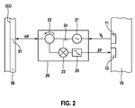
- Fig. 2 shows one for the embodiment of Fig. 1 suitable embodiment of a transmitting and receiving unit 20 in more detail.
- reference numerals designate the same or equivalent elements.
- the transmitting and receiving unit 20 has a generator 21 for generating an RF signal.
- the frequency f of the RF signal can be varied via a control signal V f frequency.
- the frequency determining signal V f is provided by the control output 11 of the controller 10 as an analog or digital signal.
- the transmitting and receiving unit 20 further comprises a circulator 22, which forwards the RF signal of the RF generator 21 via an output to the RF input and output 31 of the distributor 30, from which it is the antenna arrangement 40, not shown here is supplied.
- An RF signal reflected from an object and received via the antenna array 40 and the splitter 30 is returned to the circulator 22 via the same port, which forwards it to a mixer 23.
- the received RF signal with the generator 21 generated and tapped to a tap 24 and the mixer supplied RF signal mixed.
- the resulting mixed signal contains a signal at a lower frequency than the high frequency, which contains information about the relative speed of the reflecting object via the Doppler shift.
- the mixed signal is passed through a low-pass filter 25, which suppresses possibly contained higher-frequency signals, as an intermediate frequency (IF) signal to the IF signal input 12 of the controller 10.
- IF intermediate frequency
- High-frequency signal components in the mixed signal can result, for example, from reflected transmission signals of other transmitting and receiving units 20 which radiate on a different frequency than the transmission and reception unit 20 considered.
- the (low) frequency filtering in the mixed signal corresponds to a frequency selection in the RF signal path of the transmitting and receiving unit 20. In this way, an HF selectivity of the transmitting and receiving unit 20 is achieved, which leads to a directional characteristic for received signals.
- Fig. 3 shows a second embodiment of a radar system with a control device and a radar sensor.
- the structure is analogous to that in Fig. 1 shown embodiment.
- the feed-in point 43r of the antenna arrangement 40 is not terminated with a terminator, but is connected to a further distributor 30, which also allows the connection of transmitting and receiving devices 20.
- indices I (left) and r (right) are used, with all elements provided with the index I pointing to the left feed point 43l and all having the index r provided elements act on the right feed point 43r.
- a number of n transmitting and receiving units 201-1 to 20l-n are provided and a number of m transmitting and receiving devices 20r-1 to 20r-m.
- the distributors 30l and 30r have a corresponding number of RF inputs and outputs 31l-1 to 31l-n and 31r-1 to 31r-m.
- An arrangement as in Fig. 3 can be shown in particular then Advantages are when the total number n + m of the intended transmitting and receiving devices 20 is large and a single distributor 30 with a corresponding number of RF inputs and outputs 31 would have too high a damping.
- the basic operating principle of the arrangement in Fig. 1 and Fig. 3 does not differ, however.
- the transmitting and receiving units 20l and 20r in the embodiment of the Fig. 3 in the Fig. 2 be used in more detail described transmitting and receiving units.
- FIGS. 4 and 5 The following will be related to the FIGS. 4 and 5 the operation of a radar sensor with multiple transmitting and receiving units 20 explained.
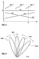
- Fig. 4 is a schematic diagram illustrating the frequency f of the emitted RF signals of the transmitting and receiving units as a function of time t in one embodiment of a radar sensor.
- the frequencies f of the transmitting and receiving units 201-1, 20l-2, 20r-1 and 20r-2 are referred to as fl-1, fl-2, fr-1 and fr-2.
- the frequency f 0 marked at the frequency axis indicates the frequency at which the antenna assembly 40 radiates in a direction perpendicular to the direction in which the antenna elements 41 are arranged. This direction is also referred to below as the basic direction.
- the transmitting and receiving unit 201-1 is operated at a constant frequency fl-1 equal to f 0
- the other transmitting and receiving units 20l-2, 20r-1 and 20r-2 are operated with sections linearly changing frequencies.
- the frequency changes are periodic in the example shown, as the sawtooth waveform of the frequency fl-2 can be seen.
- the period length may be selected differently for the various transmitting and receiving units 20. It is also conceivable that one or more of the frequencies are changed depending on a detected object, for example, to keep this in the observation area (object tracking).
- the arrows at the ends of the directional lobes 50 in Fig. 5 symbolize thereby the current direction of movement of the directional lobes 50.
- a relation to the frequency f 0 smaller frequency leads to a tilted right out of the basic direction out directional lobe, whereas a frequency greater than the frequency f 0 leads to a directional leftwave pivoted to the left.
- the overall directivity pattern shown gives consequently as a superposition of the directional lobe 501-1, which is unchanged time aligned with their main beam direction along the primary direction, the directional lobe 50l-2, which is pivoted to the left and continues to move in this direction , the directional lobe 50r-1, which is slightly pivoted to the right and moves to the left, and the directional lobe 50r-2, which is pivoted to the right and continues to pivot in that direction.
- a signal reflected by an object initially only contains information about the speed of the reflecting object.
- information about the signal propagation time is needed, which can be obtained, for example, from pulsed radar signals.
- transit time information can be obtained via frequency modulation (FMCW Frequency Modulated Continuous Wave).
- FMCW Frequency Modulated Continuous Wave In the angle-resolved radar sensors presented in the context of the application, a periodic frequency change used for angular variation can be used simultaneously to obtain distance information from the reflected radar signal win. For this it is necessary to evaluate the received radar signal over at least two periods of the frequency change.
- a further processing of the signals received at the intermediate frequency signal inputs 12 of the control device 10 can advantageously take place via analog / digital converters and subsequent frequency analysis, for example by a fast Fourier transform (FFT).
- FFT fast Fourier transform
- the controller 10 is not part of the radar sensor. However, it may also be implemented as an integral part of the radar sensor.
Landscapes
- Engineering & Computer Science (AREA)
- Radar, Positioning & Navigation (AREA)
- Remote Sensing (AREA)
- Physics & Mathematics (AREA)
- Computer Networks & Wireless Communication (AREA)
- General Physics & Mathematics (AREA)
- Electromagnetism (AREA)
- Computer Security & Cryptography (AREA)
- Radar Systems Or Details Thereof (AREA)
- Variable-Direction Aerials And Aerial Arrays (AREA)
Description
- Die Erfindung betrifft einen Radarsensor mit einer Antennenanordnung, die mehrere nebeneinander angeordnete Antennenelemente und mindesten einen Einspeisepunkt an einem äußeren Antennenelement aufweist. Die Antennenelemente sind über Verzögerungsstrecken seriell miteinander verbunden.
- Radarsensoren werden zunehmend in Kraftfahrzeugen zur Bestimmung von Abständen und Relativgeschwindigkeiten zu vorausfahrenden Fahrzeugen eingesetzt. Sie machen Abstandswarnungen oder eine abstandsbasierte automatische Geschwindigkeitskontrolle (ACC - Adaptive Cruise Control) möglich.
- Antennenanordnungen der genannten Art, die auch als Phased-Array Antennen bezeichnet werden, haben eine starke Richtwirkung und erlauben so den Aufbau von winkelaufgelösten Radarsensoren. Die Verzögerungsstrecken bedingen Phasenverschiebungen zwischen den von den einzelnen hintereinandergeschalteten Antennenelementen abgestrahlten Wellen. Die Antennenanordnungen sind so ausgelegt, dass bei der von dem Radarsensor benutzten Radarfrequenz, z.B. im Bereich von 76 Gigaherz (GHz), konstruktive und destruktive Interferenz der abgestrahlten Wellen zu einer keulenförmige Richtcharakteristik des von der Antennenanordnung abgestrahlten Radarfeldes führt. Durch eine Variation der Sende- bzw. Empfangsfrequenz kann die ausgebildete Richtkeule verschwenkt werden.
- Durch Frequenzvariation kann somit Information über vorausfahrende Fahrzeuge winkelaufgelöst gewonnen werden. Der vor einem Kraftfahrzeug liegende Bereich kann entsprechend winkelaufgelöst abgetastet ("gescannt") werden. Allerdings sind die Scanzeiten durch das Verschwenken der Richtkeulen über den gesamten Betrachtungswinkel groß. Zudem wird das Umfeld zu einem bestimmten Zeitpunkt nur jeweils an einem einzelnen Schwenkwinkel der Breite der Richtkeule erfasst.
- Irving W. Hammer, "Frequency-scanned arrays", in: Merrill I. Skolnik: "Radar Hand-book", 1. Januar 1970, Mc Graw-Hill, New York, XP2618616 beschreibt eine Antennenordnung mit mehreren in einer Reihe angeordneten Abstrahleinrichtungen, die mit Verzögerungsstrecken seriell miteinander verbunden sind. Die Antennenanordnung weist einen äußeren Einspeisepunkt auf. Weiter wird die Erzeugung mehrerer Signalpulse unterschiedlicher Frequenz beschrieben, wobei das Empfangssignal in unabhängigen Schmalbandverstärkern verstärkt wird, die jeweils auf die abgestrahlten Frequenzen abgestimmt sind. Es handelt sich um ein herkömmliches Pulsradar, bei dem während der Laufzeit eines Pulses auf Echos gewartet wird.
-
US 2 810 905 A beschreibt ein Pulsradarsystem, bei dem nach einander verschiedene Frequenzen ausgesandt werden. -
US 4 864 308 A beschreibt ein Radiometer. Frequenzen von an entgegengesetzten Enden der Antenne angeschlossenen Empfangseinheiten sind miteinander so gekoppelt, dass beide für die gleiche Richtung sensitiv sind. - W. Mayer et al., "A novel direct-imaging radar sensor with frequency scanned antenna", 2003 IEEE MTT-S International Microwave Symposium Digest, New York, Bd. 3, 8. Juni 2003, Seiten 1941-1944, XP10746708 beschreibt ein FMCW-Radar mit einer frequenzgescannten Antenne.
- Aus der Druckschrift
DE 10 2006 032 540 A1 ist ein Radarsensor bekannt, bei dem mehrere unabhängige Antennen vorgesehen sind. Die Antennen sind versetzt in Bezug auf eine optische Achse einer gemeinsamen Radarlinse angeordnet. Jede einzelne Antenne weist eine vorgegebene Richtcharakteristik auf, wobei durch die Anordnung der einzelnen Antennen und die gemeinsame Radarlinse die Antennen verschiedene Winkelbereiche abdecken. Auf diese Weise ist eine gleichzeitige winkelaufgelöste Erfassung verschiedener Winkelbereiche möglich, wobei der Radarsensor jedoch durch die Verwendung unabhängiger Antennen und der Radarlinse mechanisch aufwendig aufgebaut ist und die Winkelbereiche nicht ohne weiteres verändert werden können. - Es ist daher eine Aufgabe der vorliegenden Erfindung, einen winkelauflösenden Radarsensor zu schaffen, der bei einfachem mechanischen Aufbau die Möglichkeit bietet, gleichzeitig mehrere Winkelbereiche zu erfassen und die erfassten Winkelbereiche auf einfache Art verschwenken zu können.
- Diese Aufgabe wird durch einen Radarsensor mit den Merkmalen des unabhängigen Anspruchs gelöst. Vorteilhafte Ausgestaltungen der Erfindung ergeben sich aus den abhängigen Ansprüchen.
- Der Radarsensor der eingangs genannten Art mit einer Antennenanordnung mit mehreren nebeneinander angeordneten Antennenelementen die über Verzögerungsstrecken seriell miteinander verbundenen sind, weist erfindungsgemäß mindestens zwei Sende- und Empfangseinheiten auf, von denen jede geeignet ist, ein Radarsignal bei einer vorgegebenen Frequenz zu erzeugen und auszuwerten. Die Sende- und Empfangseinheiten sind für die FMCW-Betriebsart ausgebildet. Die mindestens zwei Sende- und Empfangseinheiten sind mit einem Einspeisepunkt der Antennenanordnung verbunden. Die Frequenzen der superponierbaren Radarsignale der mindestens zwei Sende- und Empfangseinheiten sind unabhängig voneinander vorgebbar.
- Als Folge der Ausgestaltung der Antennenanordnung mit nebeneinander angeordneten Antennenelementen und zwischen diesen liegenden Verzögerungsstrecken führt jedes der Radarsignale einer Sende- und Empfangseinheit zur Abstrahlung eines gerichteten Radarfeldes. Die Richtung wird von der Frequenz des Radarsignals der jeweiligen Sende- und Empfangseinheit bestimmt. Insgesamt entsteht durch Superposition der Einzelsignale einer jeden Sende- und Empfangseinheit 20 so ein Radarfeld, das sich aus der Überlagerung von mindestens zwei gerichteten Radarfeldern zusammensetzt. Somit können mindestens zwei - bei mehreren Sende- und Empfangseinheiten auch mehrere - Winkelbereiche gleichzeitig erfasst werden. Die Winkelbereiche können zudem auf einfache Weise durch Variation der Frequenzen verschwenkt werden. Die Ausgestaltung der Antennenanordnung als Phased-Array Antenne erlaubt zudem einen einfachen mechanischen Aufbau.
- Die Erfindung wird nachfolgend anhand von Ausführungsbeispielen mit Hilfe von fünf Figuren näher erläutert.
- Es zeigt:
- Fig. 1
- ein erstes Ausführungsbeispiel eines Radarsensors mit einer Steuereinrichtung,
- Fig. 2
- eine Sende- und Empfangseinheit zur Verwendung in einem Radarsensor,
- Fig. 3
- ein zweites Ausführungsbeispiel eines Radarsensors mit einer Steuereinrichtung,
- Fig. 4
- ein Diagramm der Zeitabhängigkeit von Sende- und Empfangsfrequenzen bei einem Radarsensor und
- Fig. 5
- ein Diagramm der Abstrahlcharakteristik eines Radarsensors.
-
Fig. 1 stellt ein Radarsystem mit einem Radarsensor und einer Steuereinrichtung schematisch dar. - Das Radarsystem weist eine Steuereinrichtung 10 und einen Radarsensor, umfassend mehrere Sende- und Empfangseinheiten 20, einen Verteiler 30 und eine Antennenanordnung 40 auf. Die Steuereinrichtung 10 weist Steuerausgänge 11 und Zwischenfrequenz (ZF)-Signaleingänge 12 auf, mit denen die Steuereinrichtung 10 mit den Sende- und Empfangseinheiten 20 verbunden ist. Weiter ist jede der Sende- und Empfangseinheiten 20 an einen Hochfrequenz (HF)-Ein- und Ausgang 31 des Verteilers 30 angeschlossen. Der Verteiler 30 hat zudem einen Antennenanschluss 32 zur Verbindung mit der Antennenanordnung 40. Die Antennenanordnung 40 umfasst mehrere, nebeneinander angeordnete Antennenelemente 41, von denen jeweils benachbarte Antennenelemente 41 über eine Verzögerungsstrecke 42 miteinander verbunden sind. Die äußeren beiden Antennenelemente 41 der auf diese Weise gebildeten linearen, kettenförmigen Anordnung sind mit Einspeisepunkten 43l und 43r verbunden, von denen einer, der Einspeisepunkt 43l, den Antennenanschluss 32 des Verteilers 30 kontaktiert und der andere, der Einspeisepunkt 43r, mit einem Abschlusselement 44, auch Terminator genannt, abgeschlossen ist.
- Bei dem Radarsystem gemäß
Fig. 1 sind für den Radarsensor eine Mehrzahl n von Sende- und Empfangseinrichtungen 20 vorgesehen. Aus Gründen der Übersichtlichkeit sind beispielhaft nur zwei Sende- und Empfangseinrichtungen 20-1 und 20-n eingezeichnet. Entsprechend der Anzahl n von Sende- und Empfangseinheiten 20 weist die Steuereinrichtung 10 eine Anzahl von n Paaren an Steuerausgängen 11 und ZF-Signaleingängen 12 auf und der Verteiler 30 weist eine Anzahl n von HF-Ein- und Ausgängen 31 auf. Über die einzelnen Steuerausgänge 11-1 bis 11-n kann von der Steuereinrichtung 10 die Frequenz einer jeden Sende und Empfangseinheit 20-1 bis 20-n unabhängig voneinander eingestellt werden. Über den Verteiler 30 werden die von den Sende- und Empfangseinheiten 20 generierten Radarhochfrequenzsignale in die Antennenanordnung 40 eingespeist. Als Folge der Ausgestaltung der Antennenanordnung 40 als Phased-Array mit den Verzögerungsstrecken 42 führt jedes der Hochfrequenzsignale einer Sende- und Empfangseinheit 20 zur Abstrahlung eines Radarsignals mit bestimmter, von der Frequenz der jeweiligen Sende- und Empfangseinheit 20 abhängigen Abstrahlrichtung. - Insgesamt entsteht durch Superposition der Einzelsignale einer jeden Sende- und Empfangseinheit 20 so ein Radarfeld, das sich aus der Überlagerung von n Abstrahlkeulen zusammensetzt. Jede der Sende- und Empfangseinheiten 20 ist zudem dazu ausgelegt, Radarsignale bei der eigenen Sendefrequenz zu empfangen. Bei entsprechender Frequenzselektion im Empfangskreis der Sende- und Empfangseinheiten 20 weist die Antennenanordnung 40 die gleiche Richtcharakteristik für das Senden und das Empfangen von Signalen auf. Dieses führt zu einer weiteren Erhöhung der Winkelsensitivität der Einzelsignale.
- Die Antennenelemente 41 der Antennenanordnung 40 können beispielsweise planare Elemente sein, die quer, bevorzugt senkrecht, zur Fahrtrichtung des Autos nebeneinander vertikal angeordnet sind, sodass die Richtkeulen parallel zur Fahrbahnoberfläche nach vorne weisen. Ein Verschwenken der Richtkeulen geschieht in der Ebene, die durch die Oberflächennormale der planaren Antennenelemente 41 und die Richtung, in der die Antennenelemente 41 nebeneinander angeordnet sind, aufgespannt wird. Somit wird ein Verschwenken in einer horizontalen Ebene nach links und rechts zur Gegenfahrbahn beziehungsweise zum Fahrbahnrand hin möglich.
- Als Verteiler 30 können beispielsweise so genannte Wilkinson-Hochfrequenzverteiler eingesetzt werden. Grundsätzlich kann jede beliebige HF-Summations- und Teilerschaltung benutzt werden, solange sie möglichst linear arbeitet, so dass keine zusätzlichen, eventuell störenden Frequenzbänder durch nichtlineare Effekte in das Radarsystem eingebracht werden.
-
Fig. 2 zeigt eine für das Ausführungsbeispiel derFig. 1 geeignete Ausgestaltung einer Sende- und Empfangseinheit 20 detaillierter. In allen Abbildungen kennzeichnen Bezugszeichen gleiche oder gleich wirkende Elemente. - Die Sende- und Empfangseinheit 20 weist einen Generator 21 zur Erzeugung eines HF-Signals auf. Die Frequenz f des HF-Signals kann über ein Steuersignal Vf Frequenz variiert werden. Das die Frequenz bestimmende Signal Vf wird von dem Steuerausgang 11 der Steuereinrichtung 10 als analoges oder digitales Signal bereitgestellt. Die Sende- und Empfangseinheit 20 weist weiter einen Zirkulator 22 auf, der das HF-Signal des HF-Generator 21 über einen Ausgang an den HF-Ein- und Ausgang 31 des Verteilers 30 weiterleitet, von dem aus es der hier nicht gezeigten Antennenordnung 40 zugeführt wird.
- Ein von einem Objekt reflektiertes und über die Antennenordnung 40 und den Verteiler 30 empfangenes und zurückgegebenes HF-Signal wird über den gleichen Anschluss wiederum dem Zirkulator 22 zugeführt, der es an einen Mischer 23 weitergibt. Im Mischer 23 wird das empfangene HF-Signal mit dem vom Generator 21 erzeugten und an einen Abgriff 24 abgegriffenen und dem Mischer zugeführten HF-Signal gemischt. Das resultierende Mischsignal enthält ein Signal auf einer kleineren Frequenz als die Hochfrequenz, das über die Dopplerverschiebung Informationen über die Relativgeschwindigkeit des reflektierenden Objekts enthält. Das gemischte Signal wird über einen Tiefpassfilter 25, der eventuell enthaltene höherfrequente Signale unterdrückt, als Zwischenfrequenz (ZF)-Signal an den ZF-Signaleingang 12 der Steuereinrichtung 10 weitergegeben.
- Hochfrequenzsignalanteile im gemischten Signal können beispielsweise durch reflektierte Sendesignale anderer Sende- und Empfangseinheiten 20, die auf einer anderen Frequenz als die betrachtete Sende- und Empfangseinheit 20 abstrahlen, herrühren. Die (Nieder-) Frequenzfilterung im gemischten Signal entspricht einer Frequenzselektion im HF-Signalweg der Sende- und Empfangseinheit 20. Auf diese Weise wird eine HF-Selektivität der Sende- und Empfangseinheit 20 erreicht, die zu einer Richtcharakteristik auch für empfangene Signale führt.
-
Fig. 3 zeigt ein zweites Ausführungsbeispiel eines Radarsystems mit einer Steuereinrichtung und einem Radarsensor. - Grundsätzlich ist der Aufbau analog zu dem in
Fig. 1 gezeigten Ausführungsbeispiel. Im Unterschied zu dem Radarsensor ausFig. 1 ist beim Ausführungsbeispiel derFig. 3 der Einspeisepunkt 43r der Antennenanordnung 40 nicht mit einem Terminator abgeschlossen, sondern mit einem weiteren Verteiler 30 verbunden, der ebenfalls den Anschluss von Sende- und Empfangseinrichtungen 20 ermöglicht. Zur Unterscheidung der in diesem Ausführungsbeispiel eingesetzten Verteiler 30 und jeweils mit diesen Verteilern 30 verbundenen Sende- und Empfangseinrichtungen 20 werden Indizes I (links) und r (rechts) benutzt, wobei alle mit dem Index I versehenen Elemente auf den linken Einspeisepunkt 43l und alle mit dem Index r versehenen Elemente auf den rechten Einspeisepunkt 43r einwirken. - Im Ausführungsbeispiel der
Fig. 3 ist eine Anzahl von n Sende- und Empfangseinheiten 201-1 bis 20l-n vorgesehen und eine Anzahl von m Sende- und Empfangseinrichtungen 20r-1 bis 20r-m. Die Verteiler 30l und 30r weisen eine entsprechende Anzahl von HF-Ein- und Ausgängen 31l-1 bis 31l-n sowie 31 r-1 bis 31r-m auf. Gleiches gilt für die Steuerausgänge 11 und die Zwischenfrequenzeingänge 12 der Steuereinrichtung 10. Eine Anordnung wie inFig. 3 gezeigt kann insbesondere dann Vorteile haben, wenn die Gesamtzahl n+m der vorgesehenen Sende- und Empfangseinrichtungen 20 groß ist und ein einzelner Verteiler 30 mit einer entsprechenden Anzahl von HF-Ein- und Ausgängen 31 eine zu hohe Dämpfung aufweisen würde. Das grundsätzliche Funktionsprinzip der Anordnung inFig. 1 undFig. 3 unterscheidet sich dabei jedoch nicht. Insbesondere können als Sende- und Empfangseinheiten 20l und 20r auch beim Ausführungsbeispiel derFig. 3 die inFig. 2 näher beschriebenen Sende- und Empfangseinheiten eingesetzt werden. - Im Folgenden wird im Zusammenhang mit den
Figuren 4 und 5 die Funktionsweise eines Radarsensors mit mehreren Sende- und Empfangseinheiten 20 erläutert. Beispielhaft wird ein Radarsensor wie im Ausführungsbeispiel derFig. 3 angegeben zugrunde gelegt, bei dem jeweils zwei Sende- und Empfangseinheiten 20l beziehungsweise 20r an den beiden Verteilern 30l beziehungsweise 30r betrieben werden (n = m = 2). -
Fig. 4 ist ein schematisches Diagramm, das die Frequenz f der abgegebenen HF-Signale der Sende- und Empfangseinheiten als Funktion der Zeit t in einem Ausführungsbeispiel eines Radarsensors darstellt. Dabei werden die Frequenzen f der Sende- und Empfangseinheiten 201-1, 20l-2, 20r-1 und 20r-2 als fl-1, fl-2, fr-1 und fr-2 bezeichnet. Die an der Frequenzachse markierte Frequenz f0 kennzeichnet die Frequenz, bei der die Antennenanordnung 40 in einer Richtung senkrecht zu der Richtung, in der die Antennenelemente 41 angeordnet sind, abstrahlt. Diese Richtung wird im Folgenden auch als Grundrichtung bezeichnet. - Wie in
Fig. 4 zu sehen ist, wird die Sende- und Empfangseinheit 201-1 mit einer konstanten Frequenz fl-1 gleich f0 betrieben wohingegen sich die übrigen Sendeund Empfangseinheiten 20l-2, 20r-1 und 20r-2 mit sich abschnittsweise linear ändernden Frequenzen betrieben werden. Die Frequenzänderungen sind im gezeigten Beispiel periodisch, wie dem sägezahnartigen Verlauf der Frequenz fl-2 ersichtlich ist. Die Periodenlänge kann für die verschiedenen Sende- und Empfangseinheiten 20 unterschiedlich gewählt sein. Auch ist denkbar, dass eine oder mehrere der Frequenzen abhängig von einem detektierten Objekt geändert werden, zum Beispiel, um dieses im Beobachtungsbereich zu halten (Object Tracking). - In
Fig. 5 ist die Gesamtrichtcharakteristik des Radarsensors, die sich aus der Überlagerung der vier den vier Sende- und Empfangseinheiten 20 zugeordneten Richtkeulen 50 ergibt, als Momentaufnahme zu einem Zeitpunkt t = tx, der inFig. 4 als gestrichelte Linie eingetragen ist, dargestellt. Die Pfeile an den Enden der Richtkeulen 50 inFig. 5 symbolisieren dabei die aktuelle Bewegungsrichtung der Richtkeulen 50. Eine gegenüber der Frequenz f0 kleinere Frequenz führt zu einer nach rechts aus der Grundrichtung heraus geschwenkten Richtkeule, wohingegen eine Frequenz größer als die Frequenz f0 zu einer nach links weg geschwenkten Richtkeule führt. - Zum Zeitpunkt t = tx ergibt sich folglich die dargestellte Gesamtrichtcharakteristik als Überlagerung der Richtkeule 501-1, die zeitlich unverändert mit ihrer Hauptstrahlrichtung entlang der Grundrichtung ausgerichtet ist, der Richtkeule 50l-2, die nach links geschwenkt ist und sich weiter in diese Richtung bewegt, der Richtkeule 50r-1, die leicht nach rechts geschwenkt ist und sich nach links bewegt sowie der Richtkeule 50r-2, die nach rechts geschwenkt ist und weiter in diese Richtung schwenkt. Mit der gezeigten Anordnung kann vorteilhaft permanent ein zentral nach vorne gerichteter, also in Fahrtrichtung weisender Winkelbereich über die Richtkeule 501-1 beobachtet werden und gleichzeitig mit der beweglichen Richtkeule 50l-2 der entgegenkommende Verkehr, sowie mit den weiteren beweglichen Richtkeulen 50r-1 und 50r-2 der Fahrbahnrand abgetastet werden. Die gleichzeitige Abtastung ermöglicht eine kontinuierliche Beobachtung relevanter Winkelbereiche bei gleichzeitig guter Winkelauflösung.
- Bei Radarsystemen mit konstanter Frequenz und kontinuierlicher, nicht gepulster Abstrahlung enthält ein durch ein Objekt reflektiertes Signal zunächst nur Informationen über die Geschwindigkeit des reflektierenden Objekts. Zur Ermittlung von Abstandsinformationen wird Information über die Signallaufzeit benötigt, die z.B. anhand von gepulsten Radarsignalen gewonnen werden kann. Bei kontinuierlich ausstrahlenden Radarsystemen kann eine Laufzeitinformation über eine Frequenzmodulation gewonnen werden (FMCW-Frequency Modulated Continuous Wave). Bei den im Rahmen der Anmeldung vorgestellten winkelaufgelösten Radarsensoren kann eine zur Winkelvariation eingesetzte periodische Frequenzänderung gleichzeitig benutzt werden, um Abstandsinformationen aus dem reflektierten Radarsignal zu gewinnen. Dazu ist es erforderlich, das empfangene Radarsignal über zumindest zwei Perioden der Frequenzänderung auszuwerten.
- Alternativ ist es möglich, eine zusätzliche, z.B. rampen- oder sägezahnförmige Frequenzmodulation über das zur Winkelvariation frequenzvariierte Signal zu legen. Eine solche Modulation kann dabei einen kleineren Frequenzhub aufweisen als die Frequenzvariation zur Winkelvariation und eine kleinere Periodenlänge haben.
- In den gezeigten Ausführungsbeispielen kann eine Weiterverarbeitung der an den Zwischenfrequenzsignaleingängen 12 der Steuereinrichtung 10 empfangenen Signale vorteilhaft über Analog/Digital-Wandler und nachfolgende Frequenzanalyse, zum Beispiel durch eine schnelle Fourier-Transformation (FFT-Fast Fourier Transform) erfolgen.
- In den obigen Ausführungsbeispielen ist die Steuereinrichtung 10 nicht Teil des Radarsensors. Sie kann jedoch ebenso als ein integraler Teil des Radarsensors ausgeführt sein.
- Neben den gezeigten Sende- und Empfangseinrichtungen 20, die über die Mischer 23 das Hochfrequenzsignal direkt auf ein Zwischenfrequenzsignal abbilden, ist ebenso der Einsatz von Superhet-Empfängern möglich, die sich zusätzlich einer Abbildung auf eine weitere Zwischenfrequenzstufe bedienen.
Claims (13)
- Radarsensor, aufweisend- eine Antennenanordnung (40) mit mehreren nebeneinander angeordneten Antennenelementen (41), die über Verzögerungsstrecken (42) seriell miteinander verbundenen sind, und mindestens einem Einspeisepunkt (43l, 43r) an einem äußeren Antennenelement (41), und- mindestens zwei Sende- und Empfangseinheiten (20), jeweils zum Erzeugen und Auswerten eines Radarsignals bei einer vorgegebenen Frequenz,wobei- die Sende- und Empfangseinheiten (20) für die FMCW-Betriebsart ausgebildet sind,- die mindestens zwei Sende- und Empfangseinheiten (20) mit dem mindestens einen Einspeisepunkt (43l, 43r) der Antennenanordnung (40) verbunden sind und- die Frequenzen der superponierbaren Radarsignale der mindestens zwei Sende- und Empfangseinheiten (20) unabhängig voneinander vorgebbar sind.
- Radarsensor nach Anspruch 1, bei dem die mindestens zwei Sende- und Empfangseinheiten (20) über einen Verteiler (30) permanent mit der Antennenanordnung (40) verbunden sind.
- Radarsensor nach Anspruch 2, bei dem der Verteiler (30) ein Wilkinson Hochfrequenz-Verteiler ist.
- Radarsensor nach Anspruch 2, bei dem der Verteiler (30) ein Hybrid Hochfrequenz-Verteiler ist.
- Radarsensor nach einem der Ansprüche 1 bis 4, bei dem die Antennenanordnung (40) zwei Einspeisepunkte (43l, 43r) aufweist, wobei alle Sende- und Empfangseinheiten (20) mit einem der Einspeisepunkte (43l, 43r) verbunden sind und der andere Einspeisepunkt (43r, 43l) mit einem Abschlusselement (44) terminiert ist.
- Radarsensor nach einem der Ansprüche 1 bis 4, bei dem die Antennenanordnung (40) zwei Einspeisepunkte (43l, 43r) und zwei Verteiler (30l, 30r) aufweist, wobei je einer der zwei Verteiler (30l, 30r) mit einem der Einspeisepunkte (43l, 43r) und mit mindestens einer Sende- und Empfangseinheit (20) verbunden ist.
- Radarsensor nach einem der Ansprüche 1 bis 6, bei dem die Verzögerungsstrecken (42) so ausgelegt sind, dass ein von der Antennenanordnung (42) abgestrahltes Radarsignal gerichtet ist, wobei die Hauptstrahlrichtung von der Frequenz des Radarsignals abhängt.
- Radarsensor nach einem der Ansprüche 1 bis 7, bei dem jede der Sende- und Empfangseinheiten (20) einen Hochfrequenz-Generator (21) zur Erzeugung des Radarsignals aufweist und bei dem ein empfangenes Radarsignal zu dessen Auswertung mit dem von dem Hochfrequenz-Generator (21) erzeugten Signal gemischt wird.
- Radarsensor nach einem der Ansprüche 1 bis 8, bei dem eine Sende- und Empfangseinheit (20) mit einer konstanten Frequenz betreibbar ist.
- Radarsensor nach einem der Ansprüche 1 bis 9, bei dem das Radarsignal von zumindest einer Sende- und Empfangseinheit (20) zur Änderung der Hauptstrahlrichtung und/oder zur Abstandsbestimmung frequenzmoduliert ist.
- Radarsensor nach Anspruch 10, bei dem die Frequenzmodulation eine rampen- oder sägezahlförmigen Modulation ist, die der Änderung der Hauptstrahlrichtung und der Abstandsbestimmung dient.
- Radarsensor nach Anspruch 10, bei dem die Frequenzmodulation sich aus einer ersten und einer zweiten rampen- oder sägezahlförmigen Modulation zusammensetzt, die sich in ihrem Frequenzhub und/oder ihrer Periodenlänge unterscheiden.
- Radarsensor nach einem der Ansprüche 1 bis 12, ausgebildet als Dopplerradar.
Applications Claiming Priority (2)
| Application Number | Priority Date | Filing Date | Title |
|---|---|---|---|
| DE102010001761A DE102010001761A1 (de) | 2010-02-10 | 2010-02-10 | Radarsensor |
| PCT/EP2010/069578 WO2011098173A1 (de) | 2010-02-10 | 2010-12-14 | Radarsensor |
Publications (2)
| Publication Number | Publication Date |
|---|---|
| EP2534730A1 EP2534730A1 (de) | 2012-12-19 |
| EP2534730B1 true EP2534730B1 (de) | 2016-09-07 |
Family
ID=43466805
Family Applications (1)
| Application Number | Title | Priority Date | Filing Date |
|---|---|---|---|
| EP10787807.6A Not-in-force EP2534730B1 (de) | 2010-02-10 | 2010-12-14 | Radarsensor |
Country Status (6)
| Country | Link |
|---|---|
| US (1) | US9190717B2 (de) |
| EP (1) | EP2534730B1 (de) |
| JP (1) | JP5763684B2 (de) |
| CN (1) | CN102754278A (de) |
| DE (1) | DE102010001761A1 (de) |
| WO (1) | WO2011098173A1 (de) |
Families Citing this family (19)
| Publication number | Priority date | Publication date | Assignee | Title |
|---|---|---|---|---|
| JP5682969B2 (ja) * | 2012-04-16 | 2015-03-11 | 日本電信電話株式会社 | アンテナ装置、および電波到来方向推定方法 |
| DE102013203789A1 (de) * | 2013-03-06 | 2014-09-11 | Robert Bosch Gmbh | Antennenanordnung mit veränderlicher Richtcharakteristik |
| LU92331B1 (en) * | 2013-12-10 | 2015-06-11 | Iee Sarl | Radar sensor with frequency dependent beam steering |
| DE102014200038A1 (de) * | 2014-01-07 | 2015-07-09 | Siemens Aktiengesellschaft | Antennenanordnung zum Lokalisieren eines bewegten Objektes und Verfahren zum Betreiben einer solchen |
| US9885777B2 (en) * | 2014-01-10 | 2018-02-06 | Raytheon Company | Detection of stealth vehicles using VHF radar |
| EP3097607B1 (de) * | 2014-01-22 | 2021-02-24 | Evolv Technology, Inc. | Strahlformung mit einer passiven apertur mit unterschiedlichen frequenzen |
| WO2015194133A1 (ja) * | 2014-06-19 | 2015-12-23 | 日本電気株式会社 | 演算装置、演算装置の制御方法、及び、演算装置の制御プログラムが記録された記憶媒体 |
| JP6923799B2 (ja) * | 2017-09-29 | 2021-08-25 | ミツミ電機株式会社 | レーダー装置 |
| DE102017218160B4 (de) | 2017-10-11 | 2024-04-18 | Audi Ag | Verfahren zum Betrieb eines Radarsystems eines Kraftfahrzeugs und Kraftfahrzeug |
| DE102018203464A1 (de) * | 2018-03-08 | 2019-09-12 | Robert Bosch Gmbh | Radarsensorsystem und Verfahren zum Betreiben eines Radarsensorsystems |
| CN110275171B (zh) * | 2018-03-15 | 2021-03-02 | 郑州宇通客车股份有限公司 | 一种车辆雷达探测控制方法及车辆 |
| DE102018203934A1 (de) * | 2018-03-15 | 2019-09-19 | Robert Bosch Gmbh | Radarsensorsystem und Verfahren zum Betreiben eines Radarsensorsystems |
| US10969465B2 (en) * | 2018-05-01 | 2021-04-06 | Mitsubishi Electric Research Laboratories, Inc. | Reference-free nonlinearity correction for FMCW-based sensing systems |
| DE102018118863A1 (de) | 2018-08-02 | 2020-02-06 | Infineon Technologies Ag | Radarvorrichtung und Verfahren zum Erzeugen unterschiedlicher Richtcharakteristika |
| DE102018214586A1 (de) * | 2018-08-29 | 2020-03-05 | Robert Bosch Gmbh | Vorrichtung zum Empfangen von Licht zur Detektion eines Objekts |
| US11309636B2 (en) * | 2019-12-18 | 2022-04-19 | Waymo Llc | Antenna structure for reducing beam squint and sidelobes |
| CN113628356A (zh) * | 2021-06-02 | 2021-11-09 | 中创未来智能技术(南京)研究院有限公司 | 一种高速公路用etc收费运维系统及方法 |
| JP7572920B2 (ja) * | 2021-07-21 | 2024-10-24 | 京セラ株式会社 | 電子機器、電子機器の制御方法、及びプログラム |
| US12540803B2 (en) | 2023-07-24 | 2026-02-03 | Raytheon Company | Tactical high power microwave antenna pedestal |
Family Cites Families (31)
| Publication number | Priority date | Publication date | Assignee | Title |
|---|---|---|---|---|
| US2810905A (en) | 1949-08-23 | 1957-10-22 | Sperry Rand Corp | High frequency directive beam apparatus |
| US3179937A (en) * | 1960-06-21 | 1965-04-20 | Frank R Abbott | Two-dimensional electromagnetic delay line |
| US3274601A (en) * | 1962-12-12 | 1966-09-20 | Blass Antenna Electronics Corp | Antenna system with electronic scanning means |
| US3400405A (en) * | 1964-06-01 | 1968-09-03 | Sylvania Electric Prod | Phased array system |
| US3419870A (en) * | 1965-05-24 | 1968-12-31 | North American Rockwell | Dual-plane frequency-scanned antenna array |
| US3434139A (en) * | 1965-07-15 | 1969-03-18 | North American Rockwell | Frequency-controlled scanning monopulse antenna |
| US3480961A (en) * | 1968-02-02 | 1969-11-25 | Univ Ohio State Res Found | Surface-wave antenna having discontinuous coaxial line |
| US4119971A (en) * | 1977-02-04 | 1978-10-10 | Hughes Aircraft Company | High data rate frequency scan slotted waveguide antenna |
| JPS53114282A (en) * | 1977-03-16 | 1978-10-05 | Tokyo Shibaura Electric Co | Ultrasonic diagnosing device |
| US4276551A (en) * | 1979-06-01 | 1981-06-30 | Hughes Aircraft Company | Electronically scanned antenna |
| US4403220A (en) * | 1980-02-05 | 1983-09-06 | Donovan John S | Radar system for collision avoidance |
| CA1234911A (en) | 1987-07-16 | 1988-04-05 | Anthony R. Raab | Frequency-scanning radiometer |
| CA1234903A (en) | 1987-07-16 | 1988-04-05 | Anthony R. Raab | Electronically scanned radar system |
| US5063390A (en) * | 1991-02-19 | 1991-11-05 | The United States Of America As Represented By The Secretary Of The Army | Non-dispersive acoustic transport time delay beam steering antenna |
| US5150336A (en) * | 1991-09-03 | 1992-09-22 | The United States Of America As Represented By The Secretary Of The Navy | Frequency dispersive transmitting array |
| JP3212789B2 (ja) * | 1993-12-29 | 2001-09-25 | 株式会社東芝 | ビーム走査アンテナ |
| GB9401361D0 (en) * | 1994-01-25 | 1994-03-23 | Philips Electronics Uk Ltd | A radar system |
| JPH11308046A (ja) | 1998-04-21 | 1999-11-05 | Mitsubishi Electric Corp | アンテナ装置 |
| JP3456167B2 (ja) | 1999-06-24 | 2003-10-14 | 三菱電機株式会社 | 多機能アンテナ装置 |
| USH2028H1 (en) * | 1999-07-22 | 2002-06-04 | United States Of America | Frequency-scan traveling wave antenna |
| US6266011B1 (en) * | 1999-09-30 | 2001-07-24 | Rockwell Science Center, Llc | Electronically scanned phased array antenna system and method with scan control independent of radiating frequency |
| US6806845B2 (en) * | 2003-01-14 | 2004-10-19 | Honeywell Federal Manufacturing & Technologies, Llc | Time-delayed directional beam phased array antenna |
| US7061443B2 (en) * | 2004-04-01 | 2006-06-13 | Raytheon Company | MMW electronically scanned antenna |
| DE112005003573T5 (de) | 2005-05-09 | 2008-03-27 | Elta Systems Ltd. | Phased-Array-Radarantenne, welche eine verminderte Suchzeit hat, und Verfahren zur Benutzung derselben |
| US7791530B2 (en) * | 2006-01-05 | 2010-09-07 | Autoliv Asp, Inc. | Time duplex apparatus and method for radar sensor front-ends |
| JP2007251589A (ja) * | 2006-03-16 | 2007-09-27 | Murata Mfg Co Ltd | アレイアンテナ装置及びrfidシステム |
| DE102006032540A1 (de) | 2006-07-13 | 2008-01-17 | Robert Bosch Gmbh | Winkelauflösender Radarsensor |
| JP2008051560A (ja) | 2006-08-22 | 2008-03-06 | Denso Corp | レーダ装置 |
| JP2008261794A (ja) | 2007-04-13 | 2008-10-30 | Mitsubishi Electric Corp | レーダ装置 |
| JP4521440B2 (ja) | 2007-12-18 | 2010-08-11 | 株式会社東芝 | アレイアンテナ装置及びその送受信モジュール |
| CN101609931B (zh) | 2008-06-20 | 2012-12-05 | 电子科技大学 | 基于时间调制的天线阵列相位控制技术及其系统实现 |
-
2010
- 2010-02-10 DE DE102010001761A patent/DE102010001761A1/de not_active Withdrawn
- 2010-12-14 JP JP2012552278A patent/JP5763684B2/ja not_active Expired - Fee Related
- 2010-12-14 WO PCT/EP2010/069578 patent/WO2011098173A1/de not_active Ceased
- 2010-12-14 CN CN2010800636587A patent/CN102754278A/zh active Pending
- 2010-12-14 US US13/519,567 patent/US9190717B2/en active Active
- 2010-12-14 EP EP10787807.6A patent/EP2534730B1/de not_active Not-in-force
Also Published As
| Publication number | Publication date |
|---|---|
| DE102010001761A1 (de) | 2011-08-11 |
| JP2013519096A (ja) | 2013-05-23 |
| US9190717B2 (en) | 2015-11-17 |
| CN102754278A (zh) | 2012-10-24 |
| WO2011098173A1 (de) | 2011-08-18 |
| US20130016001A1 (en) | 2013-01-17 |
| JP5763684B2 (ja) | 2015-08-12 |
| EP2534730A1 (de) | 2012-12-19 |
Similar Documents
| Publication | Publication Date | Title |
|---|---|---|
| EP2534730B1 (de) | Radarsensor | |
| DE112011102901B4 (de) | Mehrbereich-Radarsystem | |
| DE19648203C2 (de) | Mehrstrahliges Kraftfahrzeug-Radarsystem | |
| EP1792203B1 (de) | Monostatischer planarer mehrstrahlradarsensor | |
| DE602004002145T2 (de) | Radaranordnung mit Schaltermatrix zur adaptiven Strahlformung im Empfangszweig und Umschalten des Sendezweigs | |
| EP2756329B1 (de) | Abbildender radarsensor mit schmaler antennenkeule und weitem winkel-detektionsbereich | |
| DE102016102241B4 (de) | Auf digitaler strahlformung basierendes auflösen von nicht-im-weg-zielen, die aufgrund von gitterkeulen in array-antennen-radars als im-weg-ziele erscheinen | |
| EP1570296B1 (de) | Einrichtung zur messung von winkelpositionen | |
| DE102004059915A1 (de) | Radarsystem | |
| EP2769236B1 (de) | Winkelauflösender radarsensor | |
| DE19714570A1 (de) | Mehrstahliges Radarsystem | |
| WO2012034736A1 (de) | Radarsensor für kraftfahrzeuge, insbesondere lca-sensor | |
| DE102009027003A1 (de) | Optimierung der Schaltreihenfolge bei geschalteten Antennenarrays | |
| EP2616839B1 (de) | Radarsensor für kraftfahrzeuge, insbesondere rca-sensor | |
| DE112017000933B4 (de) | Radar mit reichweitenunabhängiger Auflösung | |
| WO2008043595A1 (de) | Winkelauflösender radarsensor für kraftfahrzeuge | |
| WO2006066781A2 (de) | Kraftfahrzeug-radarsystem mit segmentweisem phasendifferenz-auswerteverfahren | |
| EP2722686A1 (de) | Interferometrisches SAR-System | |
| WO2004046752A1 (de) | Verfahren und vorrichtung zur erstellung eines radarbildes mit einem frequenzmodulierten dauerstrichradar | |
| EP2225582B1 (de) | Monostatischer mehrstrahl-radarsensor, sowie verfahren | |
| DE102007058236A1 (de) | Bistatische Arrayantenne sowie Verfahren | |
| DE102010041755A1 (de) | Radarsystem | |
| EP1969394A1 (de) | Radarvorrichtung | |
| DE102004045108A1 (de) | Empfangssystem für die Bestimmung eines Ziel-Ablagewinkels | |
| DE102016206787A1 (de) | Radarsensor für Kraftfahrzeuge |
Legal Events
| Date | Code | Title | Description |
|---|---|---|---|
| PUAI | Public reference made under article 153(3) epc to a published international application that has entered the european phase |
Free format text: ORIGINAL CODE: 0009012 |
|
| 17P | Request for examination filed |
Effective date: 20120910 |
|
| AK | Designated contracting states |
Kind code of ref document: A1 Designated state(s): AL AT BE BG CH CY CZ DE DK EE ES FI FR GB GR HR HU IE IS IT LI LT LU LV MC MK MT NL NO PL PT RO RS SE SI SK SM TR |
|
| DAX | Request for extension of the european patent (deleted) | ||
| GRAP | Despatch of communication of intention to grant a patent |
Free format text: ORIGINAL CODE: EPIDOSNIGR1 |
|
| RIC1 | Information provided on ipc code assigned before grant |
Ipc: G01S 13/93 20060101ALI20160519BHEP Ipc: G01S 7/03 20060101ALI20160519BHEP Ipc: H01Q 25/00 20060101ALI20160519BHEP Ipc: H01Q 21/08 20060101ALI20160519BHEP Ipc: H01Q 3/22 20060101AFI20160519BHEP Ipc: H01Q 1/32 20060101ALI20160519BHEP Ipc: G01S 13/42 20060101ALI20160519BHEP Ipc: G01S 13/34 20060101ALI20160519BHEP |
|
| INTG | Intention to grant announced |
Effective date: 20160615 |
|
| GRAS | Grant fee paid |
Free format text: ORIGINAL CODE: EPIDOSNIGR3 |
|
| GRAA | (expected) grant |
Free format text: ORIGINAL CODE: 0009210 |
|
| AK | Designated contracting states |
Kind code of ref document: B1 Designated state(s): AL AT BE BG CH CY CZ DE DK EE ES FI FR GB GR HR HU IE IS IT LI LT LU LV MC MK MT NL NO PL PT RO RS SE SI SK SM TR |
|
| REG | Reference to a national code |
Ref country code: GB Ref legal event code: FG4D Free format text: NOT ENGLISH |
|
| REG | Reference to a national code |
Ref country code: CH Ref legal event code: EP |
|
| REG | Reference to a national code |
Ref country code: IE Ref legal event code: FG4D Free format text: LANGUAGE OF EP DOCUMENT: GERMAN |
|
| REG | Reference to a national code |
Ref country code: AT Ref legal event code: REF Ref document number: 827585 Country of ref document: AT Kind code of ref document: T Effective date: 20161015 |
|
| REG | Reference to a national code |
Ref country code: DE Ref legal event code: R096 Ref document number: 502010012376 Country of ref document: DE |
|
| REG | Reference to a national code |
Ref country code: FR Ref legal event code: PLFP Year of fee payment: 7 |
|
| REG | Reference to a national code |
Ref country code: LT Ref legal event code: MG4D |
|
| REG | Reference to a national code |
Ref country code: NL Ref legal event code: MP Effective date: 20160907 |
|
| PG25 | Lapsed in a contracting state [announced via postgrant information from national office to epo] |
Ref country code: FI Free format text: LAPSE BECAUSE OF FAILURE TO SUBMIT A TRANSLATION OF THE DESCRIPTION OR TO PAY THE FEE WITHIN THE PRESCRIBED TIME-LIMIT Effective date: 20160907 Ref country code: LT Free format text: LAPSE BECAUSE OF FAILURE TO SUBMIT A TRANSLATION OF THE DESCRIPTION OR TO PAY THE FEE WITHIN THE PRESCRIBED TIME-LIMIT Effective date: 20160907 Ref country code: RS Free format text: LAPSE BECAUSE OF FAILURE TO SUBMIT A TRANSLATION OF THE DESCRIPTION OR TO PAY THE FEE WITHIN THE PRESCRIBED TIME-LIMIT Effective date: 20160907 Ref country code: HR Free format text: LAPSE BECAUSE OF FAILURE TO SUBMIT A TRANSLATION OF THE DESCRIPTION OR TO PAY THE FEE WITHIN THE PRESCRIBED TIME-LIMIT Effective date: 20160907 Ref country code: NO Free format text: LAPSE BECAUSE OF FAILURE TO SUBMIT A TRANSLATION OF THE DESCRIPTION OR TO PAY THE FEE WITHIN THE PRESCRIBED TIME-LIMIT Effective date: 20161207 |
|
| PG25 | Lapsed in a contracting state [announced via postgrant information from national office to epo] |
Ref country code: GR Free format text: LAPSE BECAUSE OF FAILURE TO SUBMIT A TRANSLATION OF THE DESCRIPTION OR TO PAY THE FEE WITHIN THE PRESCRIBED TIME-LIMIT Effective date: 20161208 Ref country code: NL Free format text: LAPSE BECAUSE OF FAILURE TO SUBMIT A TRANSLATION OF THE DESCRIPTION OR TO PAY THE FEE WITHIN THE PRESCRIBED TIME-LIMIT Effective date: 20160907 Ref country code: LV Free format text: LAPSE BECAUSE OF FAILURE TO SUBMIT A TRANSLATION OF THE DESCRIPTION OR TO PAY THE FEE WITHIN THE PRESCRIBED TIME-LIMIT Effective date: 20160907 Ref country code: ES Free format text: LAPSE BECAUSE OF FAILURE TO SUBMIT A TRANSLATION OF THE DESCRIPTION OR TO PAY THE FEE WITHIN THE PRESCRIBED TIME-LIMIT Effective date: 20160907 Ref country code: SE Free format text: LAPSE BECAUSE OF FAILURE TO SUBMIT A TRANSLATION OF THE DESCRIPTION OR TO PAY THE FEE WITHIN THE PRESCRIBED TIME-LIMIT Effective date: 20160907 |
|
| PG25 | Lapsed in a contracting state [announced via postgrant information from national office to epo] |
Ref country code: RO Free format text: LAPSE BECAUSE OF FAILURE TO SUBMIT A TRANSLATION OF THE DESCRIPTION OR TO PAY THE FEE WITHIN THE PRESCRIBED TIME-LIMIT Effective date: 20160907 Ref country code: EE Free format text: LAPSE BECAUSE OF FAILURE TO SUBMIT A TRANSLATION OF THE DESCRIPTION OR TO PAY THE FEE WITHIN THE PRESCRIBED TIME-LIMIT Effective date: 20160907 |
|
| PG25 | Lapsed in a contracting state [announced via postgrant information from national office to epo] |
Ref country code: SK Free format text: LAPSE BECAUSE OF FAILURE TO SUBMIT A TRANSLATION OF THE DESCRIPTION OR TO PAY THE FEE WITHIN THE PRESCRIBED TIME-LIMIT Effective date: 20160907 Ref country code: PT Free format text: LAPSE BECAUSE OF FAILURE TO SUBMIT A TRANSLATION OF THE DESCRIPTION OR TO PAY THE FEE WITHIN THE PRESCRIBED TIME-LIMIT Effective date: 20170109 Ref country code: BG Free format text: LAPSE BECAUSE OF FAILURE TO SUBMIT A TRANSLATION OF THE DESCRIPTION OR TO PAY THE FEE WITHIN THE PRESCRIBED TIME-LIMIT Effective date: 20161207 Ref country code: BE Free format text: LAPSE BECAUSE OF NON-PAYMENT OF DUE FEES Effective date: 20161231 Ref country code: CZ Free format text: LAPSE BECAUSE OF FAILURE TO SUBMIT A TRANSLATION OF THE DESCRIPTION OR TO PAY THE FEE WITHIN THE PRESCRIBED TIME-LIMIT Effective date: 20160907 Ref country code: SM Free format text: LAPSE BECAUSE OF FAILURE TO SUBMIT A TRANSLATION OF THE DESCRIPTION OR TO PAY THE FEE WITHIN THE PRESCRIBED TIME-LIMIT Effective date: 20160907 Ref country code: PL Free format text: LAPSE BECAUSE OF FAILURE TO SUBMIT A TRANSLATION OF THE DESCRIPTION OR TO PAY THE FEE WITHIN THE PRESCRIBED TIME-LIMIT Effective date: 20160907 Ref country code: IS Free format text: LAPSE BECAUSE OF FAILURE TO SUBMIT A TRANSLATION OF THE DESCRIPTION OR TO PAY THE FEE WITHIN THE PRESCRIBED TIME-LIMIT Effective date: 20170107 |
|
| REG | Reference to a national code |
Ref country code: DE Ref legal event code: R097 Ref document number: 502010012376 Country of ref document: DE |
|
| PG25 | Lapsed in a contracting state [announced via postgrant information from national office to epo] |
Ref country code: IT Free format text: LAPSE BECAUSE OF FAILURE TO SUBMIT A TRANSLATION OF THE DESCRIPTION OR TO PAY THE FEE WITHIN THE PRESCRIBED TIME-LIMIT Effective date: 20160907 |
|
| PLBE | No opposition filed within time limit |
Free format text: ORIGINAL CODE: 0009261 |
|
| STAA | Information on the status of an ep patent application or granted ep patent |
Free format text: STATUS: NO OPPOSITION FILED WITHIN TIME LIMIT |
|
| PG25 | Lapsed in a contracting state [announced via postgrant information from national office to epo] |
Ref country code: DK Free format text: LAPSE BECAUSE OF FAILURE TO SUBMIT A TRANSLATION OF THE DESCRIPTION OR TO PAY THE FEE WITHIN THE PRESCRIBED TIME-LIMIT Effective date: 20160907 |
|
| REG | Reference to a national code |
Ref country code: CH Ref legal event code: PL |
|
| 26N | No opposition filed |
Effective date: 20170608 |
|
| PG25 | Lapsed in a contracting state [announced via postgrant information from national office to epo] |
Ref country code: SI Free format text: LAPSE BECAUSE OF FAILURE TO SUBMIT A TRANSLATION OF THE DESCRIPTION OR TO PAY THE FEE WITHIN THE PRESCRIBED TIME-LIMIT Effective date: 20160907 |
|
| PG25 | Lapsed in a contracting state [announced via postgrant information from national office to epo] |
Ref country code: MC Free format text: LAPSE BECAUSE OF FAILURE TO SUBMIT A TRANSLATION OF THE DESCRIPTION OR TO PAY THE FEE WITHIN THE PRESCRIBED TIME-LIMIT Effective date: 20160907 |
|
| REG | Reference to a national code |
Ref country code: IE Ref legal event code: MM4A |
|
| PG25 | Lapsed in a contracting state [announced via postgrant information from national office to epo] |
Ref country code: CH Free format text: LAPSE BECAUSE OF NON-PAYMENT OF DUE FEES Effective date: 20161231 Ref country code: LU Free format text: LAPSE BECAUSE OF NON-PAYMENT OF DUE FEES Effective date: 20161214 Ref country code: LI Free format text: LAPSE BECAUSE OF NON-PAYMENT OF DUE FEES Effective date: 20161231 |
|
| PG25 | Lapsed in a contracting state [announced via postgrant information from national office to epo] |
Ref country code: IE Free format text: LAPSE BECAUSE OF NON-PAYMENT OF DUE FEES Effective date: 20161214 |
|
| REG | Reference to a national code |
Ref country code: FR Ref legal event code: PLFP Year of fee payment: 8 |
|
| REG | Reference to a national code |
Ref country code: BE Ref legal event code: MM Effective date: 20161231 |
|
| REG | Reference to a national code |
Ref country code: AT Ref legal event code: MM01 Ref document number: 827585 Country of ref document: AT Kind code of ref document: T Effective date: 20161214 |
|
| PG25 | Lapsed in a contracting state [announced via postgrant information from national office to epo] |
Ref country code: AT Free format text: LAPSE BECAUSE OF NON-PAYMENT OF DUE FEES Effective date: 20161214 Ref country code: CY Free format text: LAPSE BECAUSE OF FAILURE TO SUBMIT A TRANSLATION OF THE DESCRIPTION OR TO PAY THE FEE WITHIN THE PRESCRIBED TIME-LIMIT Effective date: 20160907 Ref country code: HU Free format text: LAPSE BECAUSE OF FAILURE TO SUBMIT A TRANSLATION OF THE DESCRIPTION OR TO PAY THE FEE WITHIN THE PRESCRIBED TIME-LIMIT; INVALID AB INITIO Effective date: 20101214 |
|
| PG25 | Lapsed in a contracting state [announced via postgrant information from national office to epo] |
Ref country code: MK Free format text: LAPSE BECAUSE OF FAILURE TO SUBMIT A TRANSLATION OF THE DESCRIPTION OR TO PAY THE FEE WITHIN THE PRESCRIBED TIME-LIMIT Effective date: 20160907 Ref country code: TR Free format text: LAPSE BECAUSE OF FAILURE TO SUBMIT A TRANSLATION OF THE DESCRIPTION OR TO PAY THE FEE WITHIN THE PRESCRIBED TIME-LIMIT Effective date: 20160907 |
|
| PG25 | Lapsed in a contracting state [announced via postgrant information from national office to epo] |
Ref country code: MT Free format text: LAPSE BECAUSE OF FAILURE TO SUBMIT A TRANSLATION OF THE DESCRIPTION OR TO PAY THE FEE WITHIN THE PRESCRIBED TIME-LIMIT Effective date: 20160907 |
|
| PG25 | Lapsed in a contracting state [announced via postgrant information from national office to epo] |
Ref country code: AL Free format text: LAPSE BECAUSE OF FAILURE TO SUBMIT A TRANSLATION OF THE DESCRIPTION OR TO PAY THE FEE WITHIN THE PRESCRIBED TIME-LIMIT Effective date: 20160907 |
|
| PGFP | Annual fee paid to national office [announced via postgrant information from national office to epo] |
Ref country code: GB Payment date: 20201222 Year of fee payment: 11 Ref country code: FR Payment date: 20201218 Year of fee payment: 11 |
|
| GBPC | Gb: european patent ceased through non-payment of renewal fee |
Effective date: 20211214 |
|
| PG25 | Lapsed in a contracting state [announced via postgrant information from national office to epo] |
Ref country code: GB Free format text: LAPSE BECAUSE OF NON-PAYMENT OF DUE FEES Effective date: 20211214 |
|
| PG25 | Lapsed in a contracting state [announced via postgrant information from national office to epo] |
Ref country code: FR Free format text: LAPSE BECAUSE OF NON-PAYMENT OF DUE FEES Effective date: 20211231 |
|
| REG | Reference to a national code |
Ref country code: DE Ref legal event code: R084 Ref document number: 502010012376 Country of ref document: DE |
|
| PGFP | Annual fee paid to national office [announced via postgrant information from national office to epo] |
Ref country code: DE Payment date: 20240227 Year of fee payment: 14 |
|
| REG | Reference to a national code |
Ref country code: DE Ref legal event code: R119 Ref document number: 502010012376 Country of ref document: DE |
|
| PG25 | Lapsed in a contracting state [announced via postgrant information from national office to epo] |
Ref country code: DE Free format text: LAPSE BECAUSE OF NON-PAYMENT OF DUE FEES Effective date: 20250701 |