EP2534732B1 - Agencement d'antenne - Google Patents
Agencement d'antenne Download PDFInfo
- Publication number
- EP2534732B1 EP2534732B1 EP10845883.7A EP10845883A EP2534732B1 EP 2534732 B1 EP2534732 B1 EP 2534732B1 EP 10845883 A EP10845883 A EP 10845883A EP 2534732 B1 EP2534732 B1 EP 2534732B1
- Authority
- EP
- European Patent Office
- Prior art keywords
- structures
- radiation elements
- antenna arrangement
- arrangement
- groups
- Prior art date
- Legal status (The legal status is an assumption and is not a legal conclusion. Google has not performed a legal analysis and makes no representation as to the accuracy of the status listed.)
- Not-in-force
Links
- 230000005855 radiation Effects 0.000 claims description 64
- 239000004020 conductor Substances 0.000 claims description 11
- 230000001747 exhibiting effect Effects 0.000 claims 1
- 230000010287 polarization Effects 0.000 description 12
- 238000005516 engineering process Methods 0.000 description 3
- 238000000926 separation method Methods 0.000 description 3
- 230000005540 biological transmission Effects 0.000 description 2
- 230000015556 catabolic process Effects 0.000 description 2
- 238000006731 degradation reaction Methods 0.000 description 2
- 239000003989 dielectric material Substances 0.000 description 2
- 125000006850 spacer group Chemical group 0.000 description 2
- 238000009933 burial Methods 0.000 description 1
- 230000001413 cellular effect Effects 0.000 description 1
- 230000003247 decreasing effect Effects 0.000 description 1
- 238000001514 detection method Methods 0.000 description 1
- 238000010586 diagram Methods 0.000 description 1
- 230000000694 effects Effects 0.000 description 1
- 238000000034 method Methods 0.000 description 1
- 230000001681 protective effect Effects 0.000 description 1
Images
Classifications
-
- H—ELECTRICITY
- H01—ELECTRIC ELEMENTS
- H01Q—ANTENNAS, i.e. RADIO AERIALS
- H01Q13/00—Waveguide horns or mouths; Slot antennas; Leaky-waveguide antennas; Equivalent structures causing radiation along the transmission path of a guided wave
- H01Q13/20—Non-resonant leaky-waveguide or transmission-line antennas; Equivalent structures causing radiation along the transmission path of a guided wave
- H01Q13/203—Leaky coaxial lines
Definitions
- the present invention discloses a novel antenna arrangement.
- leaky cables also sometimes referred to as leaky feeders or radiating cables.
- a leaky cable is, as the name implies, a cable which is capable of conducting electrical energy, and which has been provided with apertures in order to make the cable radiate, i.e. to allow some of the energy to "leak" from the cable, thus enabling the cable act as an antenna.
- Such an antenna i.e. a leaky cable, will be able to act as both a receiving and a transmitting antenna.
- Due to its nature of a cable, a "leaky cable antenna” will, as compared to a traditional antenna, act more like a line source than a point source, thus making it easier to obtain coverage in tunnels or where a high degree of "shadowing" occurs when using a point source antenna.
- An example of the latter is an indoor scenario, e.g. an office landscape.
- US Patent 4,091,367 and US Patent 5,247,270 disclose leaky cable systems which are intended for use as intruder detection systems, with the disclosure of the latter document being particularly intended for burial below ground or for use in mines.
- JP 2005286812 discloses an arrangement with two leaky cables alongside each other, each cable has a number of radiation elements evenly distributed along is length.
- the radiation elements are in groups of two different polarization directions, and the cables are located such that a group of one polarization in one of the cables is next to a group of other polarization in the other cable.
- Two radio frequency bands are intended to be handled by the arrangement, each by a respective of the two cables.
- the present invention is defined by independent claim 1. is an object of the present invention to provide an antenna arrangement with leaky cables which has improved properties as compared to the prior art.
- Such an antenna arrangement is offered by the present invention in that it discloses an antenna arrangement which comprises a first and a second elongated structure for guiding an electromagnetic wave.
- Each of the structures exhibits a longitudinal and a transversal direction of extension and are positioned alongside each other in their longitudinal direction of extension.
- each of the structures comprises at least one group of radiation elements.
- the first and second structures are arranged so that for at least two adjacent sections, one in each structure, the groups of radiation elements are distributed along the two structures such that the longitudinal separation between nearest among the groups in the two structures is at a minimum longitudinal distance d 2 .
- An advantage of the invention is thus that the inventive antenna arrangement can be used for transmit and/or receive diversity between the two structures, by space diversity, as will be realized from the detailed description given below.
- a further advantage of the invention is that the correlation between the two structures can be kept low, which means that the antenna arrangement of the invention can also be used for so called MIMO applications, Multiple Input Multiple Output.
- MIMO is a technology which is becoming increasingly common, and which needs at least two channels (e.g. two antennas) with a low degree of correlation between them.
- the groups of radiation elements in the structures are arranged at a minimum longitudinal distance to the nearest group of radiation elements in the other structure.
- the first and second structures are arranged so that their longitudinal directions of extension are in parallel with each other.
- the first and second structures are one of the following:
- the radiation elements are through-going apertures in a conductor in the first and second structure.
- the antenna arrangement comprises a locking arrangement for locking the first and the second structures in a predetermined position relative to each other with respect to their longitudinal extensions as well as to a distance between the structures and/or a radial rotation between the structures.
- the locking arrangement comprises a sheathing of a non-conducting material surrounding each of said first and second structures.
- the invention will be described by means of examples which comprise two structures or cables, which will also be referred to as "antennas". Again, the number of cables shown is merely an example intended to enhance the reader's understanding of the invention, and should not be seen as limiting the number of cables which can be used within the scope of the present invention.
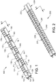
- fig 1 there is shown a first example of an embodiment 100 of the invention which is intended to provide so called spatial diversity between two cables, i.e. two "antennas", which is a manner in which the two cables or structures will also be referred to from now on.
- the embodiment 100 comprises a first 110 and a second 120 coaxial cable, each of which comprises an inner conductor 104, 107 and an outer conductor 102, 105, which are separated from the respective inner conductor by a dielectric layer 103, 106.
- An alternative to a dielectric layer is a dielectric spacer, i.e. a spacer of a dielectric material.
- the first cable 110 comprises groups 111, 130, 150, 170 of radiation elements with at least one radiation element 131, 151, in each group
- the second cable 120 also comprises groups 140, 160, of radiation elements with at least one radiation element 141, 161, in each group.
- the radiation elements in fig 1 have been provided with reference numbers.
- the radiation elements of the embodiment 100 are elongated slots which are through-going perforations in the outer conductor 102, 105, and have a main direction of extension which makes the slots radiate.
- the main direction of extension is suitably the same for all of the slots in one and the same group, and is preferably in this embodiment also the same between all of the groups in one and the same cable.
- the term "main direction of extension" is used here, since a slot will also have a "secondary" or "crosswise" direction of extension.
- the main direction of extension which makes a slot radiate differs between different kinds of cables: in a coaxial cable, as shown in the drawings, the main direction of extension should not coincide with the cable's main length of extension. A suitable deviation is 10 degrees or greater.
- the main direction of extension of a slot can coincide with that of the structure or cable and still radiate.
- the shape of the radiation elements can be chosen from a wide variety of different kinds of perforations in the outer conductor, although preferred embodiments include elongated rectangular or oval slots. It should however be pointed out that most shapes of perforations will give rise to a radiating effect. Also, with reference to other kinds of possible structures for guiding an electromagnetic wave, such as waveguides or strip line and micro strip structures, it can be pointed out that the perforations which form the radiation elements should be made in the conductor of such structures.
- fig 1 Also shown in fig 1 is a coordinate system which indicates an axial, A, and a radial, R, direction of extension of the two cables 110, 120, which in this example are arranged so that their axial extensions are essentially in parallel to each other.
- each group of radiation elements in a cable is spaced apart from immediately neighbouring groups in the same cable by a minimum distance of d 1 , which is suitably designed so as to be at least the extension of a group of radiation elements.
- the closest longitudinal distance between the outer edges of two groups of radiation elements, one in each cable, is kept above a minimum distance d 2 , which is shown in fig 1 .
- the principle employed in the embodiment which gives spatial diversity is that the groups of radiation elements in the two structures are distributed along the two structures in such a manner that a group in one structure overlaps a group in the other structure partially or not at all, the latter being the case in the embodiment shown in fig 1 , with the longitudinal separation between groups in the two structures being at least d 2 .
- overlap is here used to mean that the minimum distance d 2 between two radiation elements in the two cables is preferably such that no point in a radiation element in one cable is arranged in a perpendicular direction from a point in a radiation element in the other cable.
- the embodiment 100 By means of the embodiment 100 and its arrangement of groups of radiation elements, if one and the same data stream D1 is transmitted through each of the cables 110, 120, the embodiment 100 will give rise to a low degree of spatial correlation between the signals emitted from the two cables, thus giving rise to so called spatial diversity.
- the embodiment 100 can also be used as an antenna for MIMO applications, Multiple Output Multiple Input.
- MIMO applications two different data streams D 1 and D 2 will be transmitted, one in each cable 110, 120, or both streams can be transmitted in both cables 110, 120, if the appropriate gain and/or phase weighting of the data streams is applied.
- MIMO is a technology which relies on a high degree of de-correlation between multiple transmitted (or received) data streams, and for this reason, the embodiment 100 is highly suitable for MIMO applications, since the groups of radiation elements arranged as described above and shown in fig 1 will give rise to a high degree of de-correlation between the signals transmitted from the two cables 110,120.
- Fig 2 shows an alternative 200, being not part of the invention, intended to provide diversity between two cables 210, 220, by means of so called polarization diversity.
- Fig 2 shows one group 230, 240, of radiation elements in each cable 210, 220, which of course is only an example. Only one radiation element 231, 241 in each group has been given a reference number, for reasons of clarity.
- the radiation elements are shown as elongated slots, but as opposed to the embodiment 100 of fig 1 , in the alternative 200 the radiation elements 231, 241 of one cable 210, 220 are arranged so that they have a main direction of extension which is common within the group but which differs from the main direction of extension of at least the closest group in the other cable by at least a predefined angle, at least 10 degrees, although a difference of 90 degrees is even more preferred, since such an angle will give rise to directions of polarization which are orthogonal between the two cables 210, 220.
- all groups in each cable have a common direction of extension.
- all radiation elements in a cable 210, 220 may be essentially parallel to each other, as shown in fig 2 . If one and the same data stream D1 is transmitted through each of the cables 210, 220, the alternative 200 will give rise to signals with differing polarizations from the two cables 210, 220, thus causing so called polarization diversity. The difference between the polarizations between the signals from the two cables 210, 220, will essentially correspond to the angle between the radiation elements in the two cables.
- the alternative 200 can also be used as an antenna for MIMO applications, Multiple Output Multiple Input.
- MIMO applications different data streams D 1 and D 2 will be transmitted, one in each of the cables 210, 220.
- MIMO is a technology which relies on a high degree of de-correlation between multiple transmitted (or received) data streams, which is a condition which will be fulfilled by the alternative 200, thus making it highly suitable for MIMO applications.
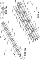
- Fig 3a shows a second alternative 300 of an antenna arrangement, being not part of the invention. Only one group 330, 340 of radiation elements is shown in each cable 310, 320, which again is merely an example. Also, as an example, the radiation elements 331, 341 in the two cables 310, 320 are shown as elongated slots, arranged equidistantly within each group.
- the second alternative 300 also gives rise to diversity between the signals emitted from the two cables or antennas 310, 320, shown in fig 3a .
- the diversity is a diversity caused by two cables 310, 320 which can have essentially similar radiation patterns or antenna diagrams, since the cables are arranged so that the radiation elements 331, 341, of the two cables 310, 320, are distributed along the structures on sides of the structures which face different directions.
- face different directions is exemplified in fig 3a and 3b as being directions which differ 180 degrees in the radial direction of the two structures, said 180 degrees in figs 3a and 3b being such that the different directions are sideways from the arrangement 300, as shown in figs 3a and 3b .
- the difference of 180 degrees can also be used to let the radiation elements face in other differing directions, such as, for example, "up” and “down", these directions being defined with relation to how the structures are shown in fig 3b .
- the condition of facing in different directions is also employed by the invention with the angular difference being other than 180 degrees, but preferably in the interval of 150 to 210 degrees.
- the difference of 180 degrees can also be expressed as saying that the cables 310, 320, are arranged so that their respective radiation elements 331, 341, are at a maximum radial distance d 4 from each other, or that the cables 310, 320, are arranged so that their respective radiation elements face away from each other in the radial directions of the cables.
- signals transmitted from the two cables 310, 320 will be de-correlated with respect to each other by means of their radiation patterns pointing in different directions. This will also make the alternative 300 suitable for MIMO applications.
- fig 4 shows an antenna arrangement 400 which comprises four individual cables 410, 420, 430, 440.
- the cables of the arrangement 400 follow the design shown in fig 2 pair-wise, i.e. a first pair of cables 410, 420 and a second pair of cables 430, 440 comprise groups of radiation elements, which groups within each pair of cables follow the principle that the radiation elements of the groups in one cable in the cable pair are parallel to each other and at an angle, here 90 degrees, with respect to the radiation elements of the group of radiation elements in the other cable in the cable pair.
- the groups of radiation elements in one cable pair are arranged so that each group's centre point essentially coincides with that of a group in the other cable in the cable pair
- the arrangement of fig 4 will give rise to polarization diversity within a cable pair.
- the groups of radiation elements of one cable pair are arranged according to the principle of fig 1 with respect to the groups of radiation elements in the other cable pair, the arrangement of fig 4 will also give rise to spatial diversity between the cable pairs.
- the principle of fig 1 is used between the cable pairs, there is a minimum distance d 2 between the groups of radiation elements in the cable pairs as well as an axial minimum distance d 1 between the radiation elements in a group.
- the arrangement 400 will give rise to polarization diversity within the cable pairs 410-420 and 430-440 as well as space diversity between the cable pairs.
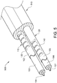
- Fig 5 shows an antenna arrangement 500 which can be applied to any of the embodiments or alternatives not being part of the invention shown in figs 1-4 , but which is here shown applied to the embodiment 100 of fig 1 : in order to ensure the proper distances and angles between the cables 110, 120 in the antenna arrangement 100, the cables 110, 120 are locked in their positions with respect to each other by a locking means 510.
- the locking means 510 can be designed in a number of ways, such as, for example interacting protrusions in one of the cables and interacting apertures in the other cable, locking bands or hook and loop type fasteners.
- these locking means assume that each cable is surrounded by a protective non-conducting sheathing, such as a rubber sheathing.
- the locking means 510 in the arrangement of fig 5 is however different from the ones listed above: instead, the cables 110, 120 shown in fig 5 are encased in a piece of dielectric material 510 which locks them in place, i.e. there is a sheathing of a non-conducting material surrounding each of the cables. Another way of achieving the same goal is to have each cable surrounded by a non-conducting sheathing, and to then have a common non-conducting sheathing for locking the cables in position.
- the degree of correlation between the signals transmitted/received from/by the cables in an arrangement of the invention should be below a predefined threshold.
- This threshold is naturally a design parameter, but a preferred maximum degree of correlation is 0.7.
- the minimum distance d 2 from at least one group of radiation elements in the two structures to the closest radiation element in the other structure is above a predefined minimum distance can also be such that there is a degree of "overlap" between one group in each of the structures 110, 120, such as for example the groups 111, 121.
- Such a design will cause degradation in the degree of de-correlation, but is still within the scope of the present invention.
- Another alternative design which will also cause degradation in the degree of de-correlation is to arrange smaller apertures or radiation elements directly opposite a group of radiation elements such as, for example, the groups 111, 121. Such smaller apertures could for example be in the shape of small holes.
Landscapes
- Variable-Direction Aerials And Aerial Arrays (AREA)
- Waveguide Aerials (AREA)
Claims (11)
- Agencement d'antenne (100, 200, 300, 400, 500) comprenant une première (110, 210, 310, 410, 430) et une seconde (120, 220, 320, 420, 440) structure allongée pour guider une onde électromagnétique, et agencé pour permettre à un flux de données respectif d'être transmis dans les deux structures, chacune desdites structures présentant une direction d'extension longitudinale (A) et une direction d'extension transversale (R), lesdites structures étant positionnées le long l'une de l'autre dans leur direction d'extension longitudinale, chacune desdites structures comprenant au moins un groupe (111, 130, 150, 140, 160, 445, 470) d'éléments de rayonnement, l'agencement d'antenne étant caractérisé en ce que les première et seconde structures sont agencées de sorte que pour au moins deux sections adjacentes, une dans chaque structure, les groupes d'éléments de rayonnement soient distribués le long des deux structures de sorte qu'un groupe (110, 130, 150) dans la première structure ne chevauche pas dans la direction d'extension longitudinale avec un groupe (120, 140, 160) dans la seconde structure, dans lequel les groupes d'éléments de rayonnement dans une desdites structures sont agencés à une distance longitudinale minimale (d2) du groupe d'éléments de rayonnement le plus proche dans l'autre structure (120, 110).
- Agencement d'antenne (100, 200, 300, 400, 500) selon la revendication 1, dans lequel la première (110, 210, 310, 410, 430) et la seconde (120, 220, 320, 420, 440) structure comprennent toutes deux une pluralité de groupes d'éléments de rayonnement, lesquels éléments de rayonnement présentent une direction d'extension principale qui est commune dans la structure, les groupes dans chaque structure étant espacés de manière équidistante le long de la direction d'extension longitudinale de la structure.
- Agencement d'antenne (100, 200, 300, 400, 500) selon la revendication 1 ou 2, dans lequel les éléments de rayonnement desdits groupes sont espacés de manière équidistante dans lesdits groupes le long de la direction d'extension longitudinale de la structure.
- Agencement d'antenne (300) selon l'une quelconque des revendications 1 à 3, dans lequel les éléments de rayonnement des groupes (330, 340) sont répartis le long des structures (310, 320) sur des côtés des structures qui font face à différentes directions, avec une différence entre lesdites directions dans l'intervalle de 150 à 210 degrés, comme elle est vue dans la direction radiale des structures.
- Agencement d'antenne (100, 200, 300, 400, 500) selon l'une quelconque des revendications 1 à 4, dans lequel les première et seconde structures sont agencées de sorte que leurs directions longitudinales soient parallèles l'une à l'autre.
- Agencement d'antenne (100, 200, 300, 400, 500) selon l'une quelconque des revendications 1 à 5, dans lequel les première et seconde structures sont l'une des suivantes :• un câble coaxial,• un guide d'ondes,• un agencement de ligne à ruban,• un agencement de microruban.
- Agencement d'antenne (100, 200, 300, 400, 500) selon la revendication 6, dans lequel les éléments de rayonnement sont des ouvertures traversantes dans un conducteur dans les première et seconde structures.
- Agencement d'antenne (500) selon l'une quelconque des revendications 1 à 7, comprenant un agencement de verrouillage pour verrouiller la première et la seconde structure dans une position prédéterminée relativement l'une à l'autre en ce qui concerne leurs extensions longitudinales ainsi qu'une distance entre les structures et/ou une rotation radiale entre les structures.
- Agencement d'antenne (500) selon la revendication 8, dans lequel l'agencement de verrouillage comprend un gainage d'un matériau non conducteur entourant chacune desdites première et seconde structures.
- Agencement d'antenne (500) selon la revendication 9, dans lequel l'agencement de verrouillage comprend un ou plusieurs des éléments suivants :• des saillies d'interaction dans un des câbles et des ouvertures d'interaction dans l'autre câble,• des bandes de verrouillage,• des dispositifs de fixation de type à crochet et boucle.
- Agencement d'antenne (500) selon la revendication 1, dans lequel la structure de l'antenne est adaptée pour être utilisée pour une application à entrées multiples sorties multiples.
Applications Claiming Priority (1)
| Application Number | Priority Date | Filing Date | Title |
|---|---|---|---|
| PCT/SE2010/050150 WO2011099901A1 (fr) | 2010-02-09 | 2010-02-09 | Agencement d'antenne |
Publications (3)
| Publication Number | Publication Date |
|---|---|
| EP2534732A1 EP2534732A1 (fr) | 2012-12-19 |
| EP2534732A4 EP2534732A4 (fr) | 2014-04-02 |
| EP2534732B1 true EP2534732B1 (fr) | 2020-07-15 |
Family
ID=44367969
Family Applications (1)
| Application Number | Title | Priority Date | Filing Date |
|---|---|---|---|
| EP10845883.7A Not-in-force EP2534732B1 (fr) | 2010-02-09 | 2010-02-09 | Agencement d'antenne |
Country Status (4)
| Country | Link |
|---|---|
| US (1) | US8890758B2 (fr) |
| EP (1) | EP2534732B1 (fr) |
| CN (1) | CN102742079B (fr) |
| WO (1) | WO2011099901A1 (fr) |
Families Citing this family (12)
| Publication number | Priority date | Publication date | Assignee | Title |
|---|---|---|---|---|
| EP2495882A1 (fr) * | 2011-02-28 | 2012-09-05 | Alcatel Lucent | Système d'antenne distribué |
| CN103326126A (zh) * | 2012-03-20 | 2013-09-25 | 西门子公司 | 一种漏泄传输线及基于漏泄传输线的mimo通信系统 |
| JP5865804B2 (ja) * | 2012-09-05 | 2016-02-17 | 三菱電機株式会社 | 複合漏洩同軸ケーブル及び侵入検知装置 |
| JP2015080010A (ja) * | 2013-10-15 | 2015-04-23 | 株式会社フジクラ | アンテナ及びダイバーシチ通信システム |
| WO2015086091A1 (fr) * | 2013-12-13 | 2015-06-18 | Telefonaktiebolaget L M Ericsson (Publ) | Agencement comportant un nœud réseau et un câble à dispersion |
| JP5903699B1 (ja) * | 2014-09-04 | 2016-04-13 | 株式会社フジクラ | デジタル無線通信装置およびデジタル無線通信システム |
| WO2016035857A1 (fr) * | 2014-09-04 | 2016-03-10 | 株式会社国際電気通信基礎技術研究所 | Dispositif et système de communication sans fil numérique |
| JP6200928B2 (ja) * | 2015-10-28 | 2017-09-20 | 株式会社フジクラ | ケーブル型アンテナ、延長ケーブル型アンテナ、複合ケーブル型アンテナ及び無線通信装置 |
| CN114696104B (zh) * | 2020-12-31 | 2024-03-26 | 江苏俊知技术有限公司 | 适用于5g通信的漏泄同轴电缆组件及其制造方法 |
| CN114696102B (zh) * | 2020-12-31 | 2024-03-12 | 江苏俊知技术有限公司 | 并联型漏泄同轴电缆组件及其制造方法 |
| CN114696103B (zh) * | 2020-12-31 | 2024-03-08 | 江苏俊知技术有限公司 | 适用于mimo技术的漏泄圆波导组件及其制造方法 |
| CN117239429B (zh) * | 2023-11-14 | 2024-02-02 | 中天射频电缆有限公司 | 一种并线型交叉极化漏缆 |
Citations (1)
| Publication number | Priority date | Publication date | Assignee | Title |
|---|---|---|---|---|
| JP2005286812A (ja) * | 2004-03-30 | 2005-10-13 | Showa Electric Wire & Cable Co Ltd | 無線lan用複合漏洩同軸ケーブル |
Family Cites Families (10)
| Publication number | Priority date | Publication date | Assignee | Title |
|---|---|---|---|---|
| NL134603C (fr) * | 1961-05-16 | |||
| US5247270A (en) * | 1987-12-01 | 1993-09-21 | Senstar Corporation | Dual leaky cables |
| GB2236907B (en) * | 1989-09-20 | 1994-04-13 | Beam Company Limited | Travelling-wave feeder type coaxial slot antenna |
| BE1010528A5 (fr) * | 1995-04-07 | 1998-10-06 | Inst Scient De Service Public | Ligne haute frequence rayonnante. |
| JP4210096B2 (ja) | 2002-10-11 | 2009-01-14 | 東芝テック株式会社 | 無線通信システム |
| JP2005190896A (ja) | 2003-12-26 | 2005-07-14 | Showa Electric Wire & Cable Co Ltd | 無線lan用ケーブル線路 |
| US7355555B2 (en) * | 2005-09-13 | 2008-04-08 | Nortel Networks Limited | Antenna |
| KR20070087927A (ko) * | 2006-02-09 | 2007-08-29 | 엘에스전선 주식회사 | 편파 다이버시티 방식의 누설동축케이블 포설 시스템 및 이를 위한 누설동축케이블 어셈블리 |
| JP4328814B2 (ja) * | 2007-05-25 | 2009-09-09 | 三菱電機株式会社 | 同軸給電スロットアレイアンテナおよび車両用レーダ装置 |
| JP4742154B2 (ja) * | 2009-02-05 | 2011-08-10 | 株式会社フジクラ | 漏洩ケーブル |
-
2010
- 2010-02-09 US US13/576,952 patent/US8890758B2/en active Active
- 2010-02-09 CN CN201080063439.9A patent/CN102742079B/zh not_active Expired - Fee Related
- 2010-02-09 WO PCT/SE2010/050150 patent/WO2011099901A1/fr not_active Ceased
- 2010-02-09 EP EP10845883.7A patent/EP2534732B1/fr not_active Not-in-force
Patent Citations (1)
| Publication number | Priority date | Publication date | Assignee | Title |
|---|---|---|---|---|
| JP2005286812A (ja) * | 2004-03-30 | 2005-10-13 | Showa Electric Wire & Cable Co Ltd | 無線lan用複合漏洩同軸ケーブル |
Also Published As
| Publication number | Publication date |
|---|---|
| US20120306711A1 (en) | 2012-12-06 |
| WO2011099901A1 (fr) | 2011-08-18 |
| CN102742079A (zh) | 2012-10-17 |
| US8890758B2 (en) | 2014-11-18 |
| EP2534732A4 (fr) | 2014-04-02 |
| CN102742079B (zh) | 2016-04-06 |
| EP2534732A1 (fr) | 2012-12-19 |
Similar Documents
| Publication | Publication Date | Title |
|---|---|---|
| EP2534732B1 (fr) | Agencement d'antenne | |
| US8988298B1 (en) | Collocated omnidirectional dual-polarized antenna | |
| Kolodziej et al. | Ring array antenna with optimized beamformer for simultaneous transmit and receive | |
| CN112164877B (zh) | 天线 | |
| JP6240202B2 (ja) | 自己接地型アンテナ装置 | |
| EP2169769B1 (fr) | Câble rayonnant | |
| US9246229B2 (en) | Antenna arrangement with an elongated structure for guiding an electromagnetic wave | |
| US20140320377A1 (en) | Multi-channel multi-sector smart antenna system | |
| US20140139395A1 (en) | Multi-sector antenna structure | |
| US9331396B2 (en) | Antenna structure having orthogonal polarizations | |
| CN102104204A (zh) | 多输入多输出天线装置 | |
| CN116073112B (zh) | 天线和基站设备 | |
| KR20160060421A (ko) | 재방사 중계기 | |
| KR20150081179A (ko) | 모노폴 또는 다이폴 안테나를 이용한 다채널 mimo 안테나 장치 | |
| JP5836097B2 (ja) | マルチビームアンテナのシステム | |
| CN114094294A (zh) | 漏缆 | |
| GB2539279A (en) | Frequency selective surface for reducing antenna coupling | |
| KR20100070555A (ko) | 안테나 시스템 및 이를 포함하는 통신 장치 | |
| KR101412135B1 (ko) | Mimo용 수평 편파 무지향성 안테나 | |
| US11189939B2 (en) | Dual-polarized wide-bandwidth antenna | |
| KR20060054342A (ko) | 다이버시티 수신 슬롯 평판 안테나 | |
| EP2437349A1 (fr) | Dispositif d'affichage | |
| US20200153599A1 (en) | Wireless communication system | |
| Balakrishnan et al. | Dual-linear polarized cavity-backed sinuous antenna with non-sequential feeding | |
| Arabi et al. | Multipolarized/Multi-Band orthogonal MIMO antenna for WiFi and WiMax applications |
Legal Events
| Date | Code | Title | Description |
|---|---|---|---|
| PUAI | Public reference made under article 153(3) epc to a published international application that has entered the european phase |
Free format text: ORIGINAL CODE: 0009012 |
|
| 17P | Request for examination filed |
Effective date: 20120906 |
|
| AK | Designated contracting states |
Kind code of ref document: A1 Designated state(s): AT BE BG CH CY CZ DE DK EE ES FI FR GB GR HR HU IE IS IT LI LT LU LV MC MK MT NL NO PL PT RO SE SI SK SM TR |
|
| DAX | Request for extension of the european patent (deleted) | ||
| A4 | Supplementary search report drawn up and despatched |
Effective date: 20140228 |
|
| RIC1 | Information provided on ipc code assigned before grant |
Ipc: H01Q 13/20 20060101AFI20140224BHEP |
|
| STAA | Information on the status of an ep patent application or granted ep patent |
Free format text: STATUS: EXAMINATION IS IN PROGRESS |
|
| 17Q | First examination report despatched |
Effective date: 20170807 |
|
| GRAP | Despatch of communication of intention to grant a patent |
Free format text: ORIGINAL CODE: EPIDOSNIGR1 |
|
| STAA | Information on the status of an ep patent application or granted ep patent |
Free format text: STATUS: GRANT OF PATENT IS INTENDED |
|
| INTG | Intention to grant announced |
Effective date: 20200429 |
|
| GRAS | Grant fee paid |
Free format text: ORIGINAL CODE: EPIDOSNIGR3 |
|
| GRAA | (expected) grant |
Free format text: ORIGINAL CODE: 0009210 |
|
| STAA | Information on the status of an ep patent application or granted ep patent |
Free format text: STATUS: THE PATENT HAS BEEN GRANTED |
|
| AK | Designated contracting states |
Kind code of ref document: B1 Designated state(s): AT BE BG CH CY CZ DE DK EE ES FI FR GB GR HR HU IE IS IT LI LT LU LV MC MK MT NL NO PL PT RO SE SI SK SM TR |
|
| REG | Reference to a national code |
Ref country code: GB Ref legal event code: FG4D Ref country code: CH Ref legal event code: EP |
|
| REG | Reference to a national code |
Ref country code: DE Ref legal event code: R096 Ref document number: 602010064946 Country of ref document: DE |
|
| REG | Reference to a national code |
Ref country code: IE Ref legal event code: FG4D |
|
| REG | Reference to a national code |
Ref country code: AT Ref legal event code: REF Ref document number: 1292020 Country of ref document: AT Kind code of ref document: T Effective date: 20200815 |
|
| REG | Reference to a national code |
Ref country code: LT Ref legal event code: MG4D |
|
| REG | Reference to a national code |
Ref country code: AT Ref legal event code: MK05 Ref document number: 1292020 Country of ref document: AT Kind code of ref document: T Effective date: 20200715 |
|
| REG | Reference to a national code |
Ref country code: NL Ref legal event code: MP Effective date: 20200715 |
|
| PG25 | Lapsed in a contracting state [announced via postgrant information from national office to epo] |
Ref country code: GR Free format text: LAPSE BECAUSE OF FAILURE TO SUBMIT A TRANSLATION OF THE DESCRIPTION OR TO PAY THE FEE WITHIN THE PRESCRIBED TIME-LIMIT Effective date: 20201016 Ref country code: NO Free format text: LAPSE BECAUSE OF FAILURE TO SUBMIT A TRANSLATION OF THE DESCRIPTION OR TO PAY THE FEE WITHIN THE PRESCRIBED TIME-LIMIT Effective date: 20201015 Ref country code: AT Free format text: LAPSE BECAUSE OF FAILURE TO SUBMIT A TRANSLATION OF THE DESCRIPTION OR TO PAY THE FEE WITHIN THE PRESCRIBED TIME-LIMIT Effective date: 20200715 Ref country code: FI Free format text: LAPSE BECAUSE OF FAILURE TO SUBMIT A TRANSLATION OF THE DESCRIPTION OR TO PAY THE FEE WITHIN THE PRESCRIBED TIME-LIMIT Effective date: 20200715 Ref country code: HR Free format text: LAPSE BECAUSE OF FAILURE TO SUBMIT A TRANSLATION OF THE DESCRIPTION OR TO PAY THE FEE WITHIN THE PRESCRIBED TIME-LIMIT Effective date: 20200715 Ref country code: LT Free format text: LAPSE BECAUSE OF FAILURE TO SUBMIT A TRANSLATION OF THE DESCRIPTION OR TO PAY THE FEE WITHIN THE PRESCRIBED TIME-LIMIT Effective date: 20200715 Ref country code: PT Free format text: LAPSE BECAUSE OF FAILURE TO SUBMIT A TRANSLATION OF THE DESCRIPTION OR TO PAY THE FEE WITHIN THE PRESCRIBED TIME-LIMIT Effective date: 20201116 Ref country code: SE Free format text: LAPSE BECAUSE OF FAILURE TO SUBMIT A TRANSLATION OF THE DESCRIPTION OR TO PAY THE FEE WITHIN THE PRESCRIBED TIME-LIMIT Effective date: 20200715 Ref country code: BG Free format text: LAPSE BECAUSE OF FAILURE TO SUBMIT A TRANSLATION OF THE DESCRIPTION OR TO PAY THE FEE WITHIN THE PRESCRIBED TIME-LIMIT Effective date: 20201015 Ref country code: ES Free format text: LAPSE BECAUSE OF FAILURE TO SUBMIT A TRANSLATION OF THE DESCRIPTION OR TO PAY THE FEE WITHIN THE PRESCRIBED TIME-LIMIT Effective date: 20200715 |
|
| PG25 | Lapsed in a contracting state [announced via postgrant information from national office to epo] |
Ref country code: IS Free format text: LAPSE BECAUSE OF FAILURE TO SUBMIT A TRANSLATION OF THE DESCRIPTION OR TO PAY THE FEE WITHIN THE PRESCRIBED TIME-LIMIT Effective date: 20201115 Ref country code: PL Free format text: LAPSE BECAUSE OF FAILURE TO SUBMIT A TRANSLATION OF THE DESCRIPTION OR TO PAY THE FEE WITHIN THE PRESCRIBED TIME-LIMIT Effective date: 20200715 Ref country code: LV Free format text: LAPSE BECAUSE OF FAILURE TO SUBMIT A TRANSLATION OF THE DESCRIPTION OR TO PAY THE FEE WITHIN THE PRESCRIBED TIME-LIMIT Effective date: 20200715 |
|
| PG25 | Lapsed in a contracting state [announced via postgrant information from national office to epo] |
Ref country code: NL Free format text: LAPSE BECAUSE OF FAILURE TO SUBMIT A TRANSLATION OF THE DESCRIPTION OR TO PAY THE FEE WITHIN THE PRESCRIBED TIME-LIMIT Effective date: 20200715 |
|
| REG | Reference to a national code |
Ref country code: DE Ref legal event code: R097 Ref document number: 602010064946 Country of ref document: DE |
|
| PG25 | Lapsed in a contracting state [announced via postgrant information from national office to epo] |
Ref country code: SM Free format text: LAPSE BECAUSE OF FAILURE TO SUBMIT A TRANSLATION OF THE DESCRIPTION OR TO PAY THE FEE WITHIN THE PRESCRIBED TIME-LIMIT Effective date: 20200715 Ref country code: RO Free format text: LAPSE BECAUSE OF FAILURE TO SUBMIT A TRANSLATION OF THE DESCRIPTION OR TO PAY THE FEE WITHIN THE PRESCRIBED TIME-LIMIT Effective date: 20200715 Ref country code: DK Free format text: LAPSE BECAUSE OF FAILURE TO SUBMIT A TRANSLATION OF THE DESCRIPTION OR TO PAY THE FEE WITHIN THE PRESCRIBED TIME-LIMIT Effective date: 20200715 Ref country code: EE Free format text: LAPSE BECAUSE OF FAILURE TO SUBMIT A TRANSLATION OF THE DESCRIPTION OR TO PAY THE FEE WITHIN THE PRESCRIBED TIME-LIMIT Effective date: 20200715 Ref country code: CZ Free format text: LAPSE BECAUSE OF FAILURE TO SUBMIT A TRANSLATION OF THE DESCRIPTION OR TO PAY THE FEE WITHIN THE PRESCRIBED TIME-LIMIT Effective date: 20200715 Ref country code: IT Free format text: LAPSE BECAUSE OF FAILURE TO SUBMIT A TRANSLATION OF THE DESCRIPTION OR TO PAY THE FEE WITHIN THE PRESCRIBED TIME-LIMIT Effective date: 20200715 |
|
| PLBE | No opposition filed within time limit |
Free format text: ORIGINAL CODE: 0009261 |
|
| STAA | Information on the status of an ep patent application or granted ep patent |
Free format text: STATUS: NO OPPOSITION FILED WITHIN TIME LIMIT |
|
| 26N | No opposition filed |
Effective date: 20210416 |
|
| PG25 | Lapsed in a contracting state [announced via postgrant information from national office to epo] |
Ref country code: SK Free format text: LAPSE BECAUSE OF FAILURE TO SUBMIT A TRANSLATION OF THE DESCRIPTION OR TO PAY THE FEE WITHIN THE PRESCRIBED TIME-LIMIT Effective date: 20200715 |
|
| PG25 | Lapsed in a contracting state [announced via postgrant information from national office to epo] |
Ref country code: SI Free format text: LAPSE BECAUSE OF FAILURE TO SUBMIT A TRANSLATION OF THE DESCRIPTION OR TO PAY THE FEE WITHIN THE PRESCRIBED TIME-LIMIT Effective date: 20200715 |
|
| PG25 | Lapsed in a contracting state [announced via postgrant information from national office to epo] |
Ref country code: MC Free format text: LAPSE BECAUSE OF FAILURE TO SUBMIT A TRANSLATION OF THE DESCRIPTION OR TO PAY THE FEE WITHIN THE PRESCRIBED TIME-LIMIT Effective date: 20200715 |
|
| REG | Reference to a national code |
Ref country code: BE Ref legal event code: MM Effective date: 20210228 |
|
| PG25 | Lapsed in a contracting state [announced via postgrant information from national office to epo] |
Ref country code: LU Free format text: LAPSE BECAUSE OF NON-PAYMENT OF DUE FEES Effective date: 20210209 Ref country code: LI Free format text: LAPSE BECAUSE OF NON-PAYMENT OF DUE FEES Effective date: 20210228 Ref country code: CH Free format text: LAPSE BECAUSE OF NON-PAYMENT OF DUE FEES Effective date: 20210228 |
|
| PG25 | Lapsed in a contracting state [announced via postgrant information from national office to epo] |
Ref country code: FR Free format text: LAPSE BECAUSE OF NON-PAYMENT OF DUE FEES Effective date: 20210228 Ref country code: IE Free format text: LAPSE BECAUSE OF NON-PAYMENT OF DUE FEES Effective date: 20210209 |
|
| PG25 | Lapsed in a contracting state [announced via postgrant information from national office to epo] |
Ref country code: BE Free format text: LAPSE BECAUSE OF NON-PAYMENT OF DUE FEES Effective date: 20210228 |
|
| PG25 | Lapsed in a contracting state [announced via postgrant information from national office to epo] |
Ref country code: HU Free format text: LAPSE BECAUSE OF FAILURE TO SUBMIT A TRANSLATION OF THE DESCRIPTION OR TO PAY THE FEE WITHIN THE PRESCRIBED TIME-LIMIT; INVALID AB INITIO Effective date: 20100209 Ref country code: CY Free format text: LAPSE BECAUSE OF FAILURE TO SUBMIT A TRANSLATION OF THE DESCRIPTION OR TO PAY THE FEE WITHIN THE PRESCRIBED TIME-LIMIT Effective date: 20200715 |
|
| PGFP | Annual fee paid to national office [announced via postgrant information from national office to epo] |
Ref country code: GB Payment date: 20230227 Year of fee payment: 14 Ref country code: DE Payment date: 20230223 Year of fee payment: 14 |
|
| PG25 | Lapsed in a contracting state [announced via postgrant information from national office to epo] |
Ref country code: MK Free format text: LAPSE BECAUSE OF FAILURE TO SUBMIT A TRANSLATION OF THE DESCRIPTION OR TO PAY THE FEE WITHIN THE PRESCRIBED TIME-LIMIT Effective date: 20200715 |
|
| PG25 | Lapsed in a contracting state [announced via postgrant information from national office to epo] |
Ref country code: TR Free format text: LAPSE BECAUSE OF FAILURE TO SUBMIT A TRANSLATION OF THE DESCRIPTION OR TO PAY THE FEE WITHIN THE PRESCRIBED TIME-LIMIT Effective date: 20200715 |
|
| REG | Reference to a national code |
Ref country code: DE Ref legal event code: R119 Ref document number: 602010064946 Country of ref document: DE |
|
| PG25 | Lapsed in a contracting state [announced via postgrant information from national office to epo] |
Ref country code: MT Free format text: LAPSE BECAUSE OF FAILURE TO SUBMIT A TRANSLATION OF THE DESCRIPTION OR TO PAY THE FEE WITHIN THE PRESCRIBED TIME-LIMIT Effective date: 20200715 |
|
| GBPC | Gb: european patent ceased through non-payment of renewal fee |
Effective date: 20240209 |
|
| PG25 | Lapsed in a contracting state [announced via postgrant information from national office to epo] |
Ref country code: DE Free format text: LAPSE BECAUSE OF NON-PAYMENT OF DUE FEES Effective date: 20240903 |
|
| PG25 | Lapsed in a contracting state [announced via postgrant information from national office to epo] |
Ref country code: GB Free format text: LAPSE BECAUSE OF NON-PAYMENT OF DUE FEES Effective date: 20240209 |
|
| PG25 | Lapsed in a contracting state [announced via postgrant information from national office to epo] |
Ref country code: GB Free format text: LAPSE BECAUSE OF NON-PAYMENT OF DUE FEES Effective date: 20240209 Ref country code: DE Free format text: LAPSE BECAUSE OF NON-PAYMENT OF DUE FEES Effective date: 20240903 |