EP2535005A1 - Ultraschalldiagnosevorrichtung und intima-media-komplexdicke-messverfahren dafür - Google Patents
Ultraschalldiagnosevorrichtung und intima-media-komplexdicke-messverfahren dafür Download PDFInfo
- Publication number
- EP2535005A1 EP2535005A1 EP10845708A EP10845708A EP2535005A1 EP 2535005 A1 EP2535005 A1 EP 2535005A1 EP 10845708 A EP10845708 A EP 10845708A EP 10845708 A EP10845708 A EP 10845708A EP 2535005 A1 EP2535005 A1 EP 2535005A1
- Authority
- EP
- European Patent Office
- Prior art keywords
- section
- blood vessel
- reliability
- wall thickness
- vascular wall
- Prior art date
- Legal status (The legal status is an assumption and is not a legal conclusion. Google has not performed a legal analysis and makes no representation as to the accuracy of the status listed.)
- Withdrawn
Links
- 238000000034 method Methods 0.000 title claims description 48
- 210000004204 blood vessel Anatomy 0.000 claims abstract description 176
- 230000002792 vascular Effects 0.000 claims abstract description 155
- 239000000523 sample Substances 0.000 claims abstract description 54
- 230000005540 biological transmission Effects 0.000 claims abstract description 8
- 230000010349 pulsation Effects 0.000 claims description 52
- 230000000747 cardiac effect Effects 0.000 claims description 33
- 230000002194 synthesizing effect Effects 0.000 claims description 16
- 230000033001 locomotion Effects 0.000 claims description 8
- 238000005259 measurement Methods 0.000 description 84
- 210000001715 carotid artery Anatomy 0.000 description 19
- 230000003205 diastolic effect Effects 0.000 description 15
- 238000007689 inspection Methods 0.000 description 15
- 238000010586 diagram Methods 0.000 description 12
- 230000010365 information processing Effects 0.000 description 11
- 230000000694 effects Effects 0.000 description 6
- 230000017531 blood circulation Effects 0.000 description 5
- 210000002808 connective tissue Anatomy 0.000 description 4
- 230000008014 freezing Effects 0.000 description 4
- 238000007710 freezing Methods 0.000 description 4
- 210000001519 tissue Anatomy 0.000 description 4
- 208000011775 arteriosclerosis disease Diseases 0.000 description 3
- 210000001367 artery Anatomy 0.000 description 3
- 238000002592 echocardiography Methods 0.000 description 3
- 208000024172 Cardiovascular disease Diseases 0.000 description 2
- 230000007423 decrease Effects 0.000 description 2
- 238000001514 detection method Methods 0.000 description 2
- 238000003745 diagnosis Methods 0.000 description 2
- 230000011000 longitudinal axis specification Effects 0.000 description 2
- 201000001320 Atherosclerosis Diseases 0.000 description 1
- 238000004458 analytical method Methods 0.000 description 1
- 210000003423 ankle Anatomy 0.000 description 1
- 239000008280 blood Substances 0.000 description 1
- 210000004369 blood Anatomy 0.000 description 1
- 210000000038 chest Anatomy 0.000 description 1
- 238000002474 experimental method Methods 0.000 description 1
- 230000000737 periodic effect Effects 0.000 description 1
- 238000003672 processing method Methods 0.000 description 1
- 238000004904 shortening Methods 0.000 description 1
- 208000024891 symptom Diseases 0.000 description 1
- 230000009466 transformation Effects 0.000 description 1
- 210000001835 viscera Anatomy 0.000 description 1
- 210000000707 wrist Anatomy 0.000 description 1
Images


Classifications
-
- A—HUMAN NECESSITIES
- A61—MEDICAL OR VETERINARY SCIENCE; HYGIENE
- A61B—DIAGNOSIS; SURGERY; IDENTIFICATION
- A61B8/00—Diagnosis using ultrasonic, sonic or infrasonic waves
- A61B8/08—Clinical applications
- A61B8/0858—Clinical applications involving measuring tissue layers, e.g. skin, interfaces
-
- A—HUMAN NECESSITIES
- A61—MEDICAL OR VETERINARY SCIENCE; HYGIENE
- A61B—DIAGNOSIS; SURGERY; IDENTIFICATION
- A61B8/00—Diagnosis using ultrasonic, sonic or infrasonic waves
- A61B8/08—Clinical applications
- A61B8/0891—Clinical applications for diagnosis of blood vessels
-
- A—HUMAN NECESSITIES
- A61—MEDICAL OR VETERINARY SCIENCE; HYGIENE
- A61B—DIAGNOSIS; SURGERY; IDENTIFICATION
- A61B8/00—Diagnosis using ultrasonic, sonic or infrasonic waves
- A61B8/52—Devices using data or image processing specially adapted for diagnosis using ultrasonic, sonic or infrasonic waves
- A61B8/5284—Devices using data or image processing specially adapted for diagnosis using ultrasonic, sonic or infrasonic waves involving retrospective matching to a physiological signal
Definitions
- the present invention relates to an ultrasonic diagnostic apparatus and a method for measuring an intima-media thickness using the apparatus.
- the intima-media complex thickness (which will be abbreviated herein as "IMT") of a carotid artery is known as one of most important indices to the status of an initial atherosclerosis.
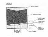
- the IMT means the thickness of an intima-media complex in the vascular wall of a carotid artery. As shown in FIG. 18 , the intima-media complex is a layer that is visible between the vascular lumen and the adventitia.
- the boundary between the vascular lumen and the intima (which will be referred to herein as a "lumen-intima boundary") and the boundary between the media and the adventitia (which will be referred to herein as a “media-adventitia boundary”) are detected and the thickness between them is measured.
- a method for automatically measuring the IMT is disclosed in Patent Document No.1, for example.
- Non-Patent Document No. 1 recommends that such an IMT measuring range have a length of 1 cm.
- the probe should be put exactly at a position where the centerline of the carotid artery can be cut vertically.
- the diameter or thickness of the carotid artery also changes without a break. That is why even when the operator holds and puts the probe at a right position, it is not always the best timing to check the status of the carotid artery.
- An ultrasonic diagnostic apparatus to which a probe with a transducer is connectible, includes: an ultrasonic signal processing section, which performs transmission processing for transmitting an ultrasonic wave toward a subject's blood vessel by driving the probe and also performs reception processing for generating a received signal based on the ultrasonic wave that has been reflected from the subject's blood vessel and received at the probe; a tomographic image processing section, which generates a tomographic image based on the received signal; a boundary detecting section, which detects the lumen-intima and media-adventitia boundaries of the blood vessel based on either the received signal or the tomographic image; a vascular wall thickness calculating section, which calculates, as a vascular wall thickness value, the interval between the lumen-intima and media-adventitia boundaries that have been detected by the boundary detecting section; a reliability determining section, which determines the reliability of the vascular wall thickness value by either a signal feature of the received signal or an image
- the signal feature includes at least one of a signal intensity and a signal intensity distribution.
- the reliability of the IMT value can be determined by either the signal intensity of the received signal or its signal intensity distribution.
- the IMT can be measured in an appropriate measuring state and a highly reliable result of measurement can be obtained.
- the image information feature includes at least one of a luminance, a luminance distribution and a shape.
- the reliability of the IMT value can be determined by either the luminance of the tomographic image, its luminance distribution or its form. As a result, the IMT can be measured in an appropriate measuring state and a highly reliable result of measurement can be obtained.
- the ultrasonic diagnostic apparatus further includes a vascular center determining section, which determines whether or not the received signal has been obtained from around a cross section of the blood vessel that passes its longitudinal center or which calculates an estimated value indicating the probability that the received signal has been obtained from around the cross section of the blood vessel that passes its longitudinal center, by either the signal feature of the received signal or the image information feature of the tomographic image at the location on the lumen-intima or media-adventitia boundary that has been detected.
- a vascular center determining section which determines whether or not the received signal has been obtained from around a cross section of the blood vessel that passes its longitudinal center or which calculates an estimated value indicating the probability that the received signal has been obtained from around the cross section of the blood vessel that passes its longitudinal center, by either the signal feature of the received signal or the image information feature of the tomographic image at the location on the lumen-intima or media-adventitia boundary that has been detected.
- the reliability determining section decides that the vascular wall thickness value have a high reliability or the reliability determining section decides that the higher the estimated value, the higher the reliability of the vascular wall thickness value.
- the vascular center determining section evaluates if there is a signal intensity or luminance distribution that is unique to the lumen-intima and media-adventitia boundaries on either the received signal or the image information of the tomographic image representing the lumen-intima and media-adventitia boundaries that have been detected, thereby determining whether or not the received signal has been obtained from around the cross section of the blood vessel that passes its longitudinal center.
- a signal intensity or luminance distribution that is unique to the lumen-intima and media-adventitia boundaries on either the received signal or the image information of the tomographic image representing the lumen-intima and media-adventitia boundaries that have been detected, thereby determining whether or not the received signal has been obtained from around the cross section of the blood vessel that passes its longitudinal center.
- the vascular center determining section estimates the length of a range where there is the signal intensity or luminance distribution, thereby determining whether or not the received signal has been obtained from around the cross section of the blood vessel that passes its longitudinal center. According to this configuration, it can be decided more properly that the received signal has been obtained from around a cross section of the blood vessel that passes its longitudinal center. Consequently, a highly reliable result of measurement can be obtained.
- the ultrasonic diagnostic apparatus further includes a pulsation detecting section, which checks the pulsating status of the blood vessel, thereby either determining whether the pulse of the blood vessel is being measured properly or calculating an estimated value indicating the probability that the pulse of the blood vessel is being measured properly. If the pulsation detecting section has decided that the pulse of the blood vessel be being measured properly or if the estimated value is beyond a predetermined reference value, the reliability determining section decides that the vascular wall thickness value have a high reliability or the reliability determining section decides that the higher the estimated value, the higher the reliability of the vascular wall thickness value. According to this configuration, by determining whether or not the pulse of the blood vessel is being measured properly, it can be seen if an appropriate measuring state has been established. Consequently, a highly reliable result of measurement can be obtained.
- the pulsation detecting section checks the pulsating status of the blood vessel by sensing a variation in the inside diameter of the blood vessel and decides that the pulse of the blood vessel be being measured properly if the variation in the inside diameter of the blood vessel has a pulse waveform. According to this configuration, it can be decided properly that the pulse of the blood vessel be being measured properly. Consequently, a highly reliable result of measurement can be obtained.
- the pulsation detecting section checks the pulsating status by detecting a feature quantity of the variation in the inside diameter of the blood vessel. According to this configuration, it can be decided more properly that the pulse of the blood vessel be being measured properly. Consequently, a highly reliable result of measurement can be obtained.
- the pulsation detecting section checks the pulsating status based on the correlation between a waveform representing the variation in the inside diameter of the blood vessel and a preregistered model waveform. According to this configuration, it can be decided more properly that the pulse of the blood vessel be being measured properly. Consequently, a highly reliable result of measurement can be obtained.
- the pulsation detecting section includes a cardiac cycle detecting section that detects a particular timing during one cardiac cycle and that either determines whether or not the pulse of the blood vessel is being measured properly before and/or after the detected timing or calculates an estimated value indicating the probability that the pulse of the blood vessel is being measured properly before and/or after the detected timing. If the pulsation detecting section has decided that the pulse of the blood vessel be being measured properly before and/or after the detected timing or if the estimated value is beyond a predetermined reference value, the reliability determining section decides that the vascular wall thickness value have a high reliability or the reliability determining section decides that the higher the estimated value, the higher the reliability of the vascular wall thickness value. According to this configuration, the IMT that varies according to the cardiac rate can be measured exactly when the IMT becomes the maximum. Consequently, a highly reliable result of measurement can be obtained.
- the pulsation detecting section checks the pulsating status by sensing a motion of the subject's tissue based on the received signal, and the cardiac cycle detecting section detects the particular timing during one cardiac cycle based on the pulsating status.
- the IMT that varies according to the cardiac rate can be measured at the best timing without using any additional function such as an ECG. Consequently, a highly reliable result of measurement can be obtained easily and with good operability.
- the cardiac cycle detecting section detects the timing based on an electrocardiographic complex. According to this configuration, the end-diastolic timing can be detected accurately using an ECG. Consequently, a highly reliable result of measurement can be obtained.
- the timing detected by the cardiac cycle detecting section is the end-diastolic timing. According to this configuration, the best timing to measure the IMT value appropriately can be determined by detecting the end-diastolic timing. Consequently, a highly reliable result of measurement can be obtained.
- the timing detected by the cardiac cycle detecting section is later than the end-diastolic timing by a predetermined amount of time. According to configuration, the exact timing when the IMT value becomes the maximum in a predetermined time after the end of the diastolic phase can be detected. Consequently, a highly reliable result of measurement can be obtained.
- the ultrasonic diagnostic apparatus further includes a longitudinal axis determining section that either determines whether or not the received signal or the tomographic image covers a longitudinal cross section of the subject's blood vessel or calculates an estimated value indicating the probability that the received signal or the tomographic image covers a longitudinal cross section of the subject' s blood vessel. If the longitudinal axis determining section has decided that the received signal or the tomographic image covers a longitudinal cross section of the subject's blood vessel or if the estimated value is beyond a predetermined reference value, the reliability determining section decides that the vascular wall thickness value have a high reliability or the reliability determining section decides that the higher the estimated value, the higher the reliability of the vascular wall thickness value. According to this configuration, by determining whether or not the received signal or the tomographic image covers a longitudinal cross section of the blood vessel, it can be seen if an appropriate measuring state has been established. Consequently, a highly reliable result of measurement can be obtained.
- the ultrasonic diagnostic apparatus further includes a stability determining section that either determines, by the magnitude of invariability of the vascular wall thickness value with time, whether or not the vascular wall thickness value is a stabilized one or calculates, based on the magnitude of invariability of the vascular wall thickness value with time, the probability that the vascular wall thickness value is a stabilized one. If the stability determining section has decided that the vascular wall thickness value is a stabilized one, the reliability determining section decides that the vascular wall thickness value have a high reliability. Or if the estimated value is beyond a predetermined reference value, the reliability determining section decides that the more removed the estimated value, the higher the reliability of the vascular wall thickness value.
- the ultrasonic diagnostic apparatus further includes an image synthesizing section that synthesizes together the decision made by the reliability determining section and the tomographic image generated by the tomographic image processing section, and a synthetic image obtained by the image synthesizing section is displayed.
- an image synthesizing section that synthesizes together the decision made by the reliability determining section and the tomographic image generated by the tomographic image processing section, and a synthetic image obtained by the image synthesizing section is displayed.
- the ultrasonic diagnostic apparatus further includes a decision criterion setting section that sets, by reference to the received signal obtained from the subject's blood vessel or information about the tomographic image generated by the tomographic image processing section and the boundary detected by the boundary detecting section, a criterion of decision for use to perform the vascular center determining process, the pulsating status checkout process, the longitudinal axis determining process or the stability determining process.
- the vascular center determining process, the pulsating status checkout process, the longitudinal axis determining process and the stability determining process can be carried out according to the attribute of the subject's tissue.
- the IMT measured value can be a more accurate and more reliable one.
- the ultrasonic signal processing section performs the transmission processing and the reception processing a number of times, thereby sequentially generating multiple received signals.
- the tomographic image processing section sequentially generates multiple tomographic images based on the multiple received signals.
- the boundary detecting section sequentially detects the lumen-intima and media-adventitia boundaries of the blood vessel based on each of the multiple received signals or each of the multiple tomographic images.
- the vascular wall thickness calculating section sequentially calculates the vascular wall thickness values based on the lumen-intima and media-adventitia boundaries of the blood vessel that have been detected sequentially.
- the reliability determining section sequentially determines the degrees of reliability of the vascular wall thickness values that have been calculated sequentially.
- the control section decides, in accordance with the decision made by the reliability determining section, that the vascular wall thickness value be defined as an intima-media thickness. And at least the tomographic images generated sequentially are displayed.
- control section freezes the tomographic images that are displayed sequentially. According to this configuration, the image displayed when the IMT is measured appropriately can be frozen.
- the ultrasonic diagnostic apparatus further includes a frame storage section, which sequentially stores, as frames, the tomographic images, the vascular wall thickness values and the decision made by the reliability determining section, and a best frame choosing section, which chooses a frame with the highest reliability from either all or a subset of the frames that have been stored in the frame storage section.
- the control section decides that the vascular wall thickness value calculated by the vascular wall thickness calculating section on the frame that has been chosen by the best frame choosing section be defined as the intima-media thickness. According to this configuration, the IMT value obtained can be reliable enough to use as the result of measurement.
- the control section freezes the tomographic images that are displayed sequentially. According to this configuration, when the IMT value obtained is a highly reliable one, the image displayed then can be frozen.
- the control section freezes the tomographic images that are displayed sequentially. According to this configuration, when the IMT value obtained is a highly reliable one, the image displayed then can be frozen.
- the best frame choosing section chooses a frame with the highest degree of reliability from the particular number of frames, of which the degrees of reliability are higher than the predetermined value and which have been written consecutively in the frame storage section. According to this configuration, the IMT measured value can be an even more reliable one.
- a method for measuring an intima-media thickness includes the steps of: performing reception processing for generating a received signal based on an ultrasonic wave that has been reflected from a subject's blood vessel and received at a probe; generating a tomographic image based on the received signal; detecting the lumen-intima and media-adventitia boundaries of the blood vessel based on either the received signal or the tomographic image; calculating, as a vascular wall thickness value, the interval between the lumen-intima and media-adventitia boundaries that have been detected; determining the reliability of the vascular wall thickness value by either a signal feature of the received signal or an image information feature of the tomographic image at a location on any of the lumen-intima and media-adventitia boundaries that have been detected; and deciding, in accordance with the result obtained, that the vascular wall thickness value should be regarded as the intima-media thickness.
- the IMT value can be measured in an appropriate measured state
- Another method for measuring an intima-media thickness includes the steps of: performing reception processing for generating a received signal based on an ultrasonic wave that has been reflected from a subject's blood vessel and received at a probe; generating a tomographic image based on the received signal; detecting the lumen-intima and media-adventitia boundaries of the blood vessel based on either the received signal or the tomographic image; calculating, as a vascular wall thickness value, the interval between the lumen-intima and media-adventitia boundaries that have been detected; checking the pulsating status of the blood vessel; determining, by either a signal feature of the received signal or an image information feature of the tomographic image at a location on the lumen-intima and/or media-adventitia boundaries that have been detected, whether or not the received signal has been obtained from around a cross section of the blood vessel that passes its center in a longitudinal direction; determining, based on the pulsating status of the blood vessel
- the ultrasonic diagnostic apparatus and IMT measuring method of the present invention just by conforming that the two boundaries between the lumen and the intima and between the media and the adventitia have been detected successfully and that the pulse of the blood vessel is being measured properly, it can be determined whether the blood vessel that is the object of IMT measurement is inspected in an appropriate state (e.g., whether the probe is put in a right position). And the IMT value that has been measured at the very best timing during one cardiac cycle is used as the final result of measurement. As a result, the IMT value thus obtained can be a highly reliable one, thus contributing to significantly increasing the accuracy and operability of the inspection of arterial sclerosis, among other things.
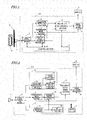
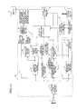
- FIG. 1 is a block diagram illustrating an ultrasonic diagnostic apparatus as a first specific preferred embodiment of the present invention.
- the ultrasonic diagnostic apparatus 101 of the first preferred embodiment includes an ultrasonic signal processing section 2, a tomographic image processing section 3, a vascular wall thickness calculating section 4, a pulsation detecting section 5, a reliability determining section 6, a control section 7 and an image synthesizing section 8.
- a probe 1 includes an ultrasonic transducer and transmits an ultrasonic wave toward a subject, and receives the ultrasonic wave that has been reflected from the subject and converts it into an electrical signal, through the ultrasonic transducer.
- the ultrasonic signal processing section 2 is designed so that the probe 1 is readily attachable to, and removable from, it and performs transmission processing by driving the ultrasonic transducer of the probe 1 with a drive pulse applied thereto at a predetermined timing to make the probe 1 send out an uitrasonic wave.
- the ultrasonic signal processing section 2 also receives an electrical signal from the probe 1 and performs reception processing that should be done to generate an ultrasonic tomographic image by amplifying and detecting the electrical signal, thereby generating a received signal.
- the ultrasonic signal processing section 2 ordinarily performs the transmission processing continuously a number of times, thereby generating received signals sequentially. That is why the processing to be described below is performed sequentially on the received signals thus generated.
- the tomographic image processing section 3 receives the received signals that have been generated by the ultrasonic signal processing section 2 and performs coordinate transformation and other kinds of processing on the received signals, thereby sequentially generating tomographic images as two-dimensional ultrasonic images.
- the vascular wall thickness calculating section 4 calculates the thickness of the wall of the subject's blood vessel that is the object of measurement.
- the pulsation detecting section 5 checks the pulsating status of the blood vessel and determines whether or not the pulse of the blood vessel is being measured properly.
- the reliability determining section 6 determines, based on the results obtained by the tomographic image processing section 3, the vascular wall thickness calculating section 4 and the pulsation detecting section 5, whether or not the status being checked and the calculated values are reliable enough to be final ones.
- the control section 7 controls the respective blocks and either decides that the result of measurement that has already had its reliability determined by the reliability determining section 6 be regarded and saved as the intima-media thickness measured or freezes the image at the point in time when such a result of measurement is obtained.
- the image synthesizing section 8 is designed so as to be connectible to the display 9 and synthesizes together the result obtained by the reliability determining section 6 and the tomographic image generated by the tomographic image processing section 3 so that the synthetic image thus obtained can be presented on the display 9 connected.
- the display 9 is a monitor that is connected to the image synthesizing section 8 and that displays its image signal thereon.
- FIG. 2 is a block diagram illustrating a more detailed configuration of this apparatus.
- FIG. 2 just illustrates details of the configuration shown in FIG. 1 , the blocks that have already been described with reference to FIG. 1 will not be described all over again if not necessary.
- the vascular wall thickness calculating section 4 includes a boundary detecting section 41 and an IMT calculating section 42.
- the boundary detecting section 41 detects the two boundaries of the blood vessel under measurement (i.e., its lumen-intima boundary and media-adventitia boundary) in a range including the IMT measuring range (see FIG. 18 ).
- the IMT calculating section 42 calculates, as the IMT, the distance between the lumen-intima and media-adventitia boundaries that have been detected by the boundary detecting section 41. In this case, max IMT is calculated as the IMT if the maximum distance in the IMT measuring range is adopted but mean IMT is calculated as the IMT if the mean distance in the IMT measuring range is adopted.
- a vascular center determining section 31 receives the tomographic image that has been generated by the tomographic image processing section 3 and the vascular boundaries that have been detected by the boundary detecting section 41 and evaluates if the lumen-intima and media-adventitia boundaries are rendered clearly at those vascular boundary locations on the tomographic image or estimates the lengths of portions of the tomographic image where the lumen-intima and media-adventitia boundaries are rendered clearly, thereby determining whether or not the probe 1 put on the subject 1 now is located right over the center of the blood vessel that is the object of measurement.
- the pulsation detecting section 5 includes a pulsation information processing section 51, a pulsating status checking section 52 and a cardiac cycle detecting section 53.
- the pulsation information processing section 51 processes the received signals that have been generated by the ultrasonic signal processing section 2, thereby extracting information from them in order to determine whether or not the blood vessel under measurement is pulsating.
- the pulsating status checking section 52 determines, based on the information that has been processed and extracted by the pulsation information processing section 51, whether or not the blood vessel is pulsating.
- the cardiac cycle detecting section 53 detects a particular timing during one cardiac cycle (e.g., the end of the diastolic phase that is a time when the heart that has contracted dilates to make the amount of the blood flow smallest).
- the blood vessel has a substantially round cross section
- FIG. 3 is a schematic representation illustrating where the echo transmitted from, and received at, the probe 1 travels with respect to a cross section of the blood vessel.
- an echo is reflected from a boundary between two regions that have mutually different acoustic impedances.
- the closer to 90 degrees the angle of incidence defined by the echo with respect to the boundary the more strongly the echo will be reflected and the clearer the reflected echo signal will be. That is why if the probe 1 put on the subject is located right over around the center of the blood vessel as shown in FIG. 3(a) (i.e., if the echo travels right through the vicinity of the center of the blood vessel), the echo is incident perpendicularly onto the lumen-intima and media-adventitia boundaries of the blood vessel and strong and clear reflected echoes are obtained from both of the two boundaries.
- the echo does not travel through the vicinity of the center of the blood vessel as shown in FIG. 3(b) , then the echo will not be incident perpendicularly onto the two boundaries and only faint and unclear reflected echoes are obtained after all.
- the lumen-intima and media-adventitia boundaries may be rendered as blurred and indistinct ones or the lumen-intima boundary may not be rendered at all.
- the probe 1 put on the subject is located right over around the center of the blood vessel.
- the vicinity of the center where the two boundaries can be rendered clearly may be defined by the distance between the acoustic line of the ultrasonic wave transmitted from the probe 1 (as indicated by the dashed line in FIG. 3 ) and the center of the cross section of the blood vessel, which may be 0.5 mm or less when measured actually. But the distance should not always be exactly equal to that value.
- the tomographic image data representing the locations of the vascular boundaries detected and their surrounding sites has a portion in which the luminance rises from one side of the detected lumen-intima boundary closer to the vascular lumen toward the intima-media complex, or a portion in which the luminance rises from one side of the detected media-adventitia boundary closer to the intima-media complex toward the adventitia, or a portion in which the luminance falls between the lumen-intima and media-adventitia boundaries detected as shown in FIG. 18 , it can be determined whether or not the lumen-intima and media-adventitia boundaries are rendered clearly at the vascular boundary locations on the tomographic image.
- the length of a portion of the tomographic image in which the lumen-intima and media-adventitia boundaries are rendered clearly may also be used as a criterion to determine whether the probe 1 put on the subject is located right over around the center of the blood vessel.
- the two boundaries described above should be rendered clearly in preferably all, or at least a certain percentage, of the IMT measuring range (see FIG. 18 ). For example, if the IMT measuring range has a length of 1 cm and the certain percentage is 75%, then at least 7.5 mm out of the overall length of 1 cm should be usable to determine whether or not the blood vessel is caught properly around its center.
- the blood vessel will contract to varying degrees according to the volume or rate of the blood flow running inside itself. That is why when the heart is in the systolic phase, the blood flow rate becomes maximum, and the blood vessel comes to have the largest inside diameter and the smallest wall thickness. On the other hand, when the heart is in the diastolic phase, the blood flow rate becomes minimum, and the blood vessel comes to have the smallest inside diameter and the largest wall thickness. That is to say, since the vascular wall thickness varies synchronously with the heartbeat, the IMT value changes according to the timing of measurement.
- FIG. 4 it is known that the distance between the two points A and B shown in FIG. 4(a) (i.e., the inside diameter of the blood vessel) varies with time as blood is pumped out of the heart, and therefore, the pulsed waveform such as the one shown in FIG. 4(b) is observed.
- the pulsating status checking section 52 does not examine whether the blood vessel is pulsating, but determines whether or not the probe is put in a right position to get information about the blood vessel properly by seeing if the pulsation of the blood vessel is measured properly.
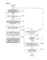
- FIG. 5 is a flowchart showing a typical procedure of operation according to the first preferred embodiment.
- Step S101 the ultrasonic signal processing section 2 performs transmission and reception controls on ultrasonic signals, thereby transmitting an ultrasonic wave with the probe 1 driven and receiving, at the probe 1, the ultrasonic wave that has been reflected form the subject. And just like a normal ultrasonic diagnostic apparatus, the ultrasonic signal processing section 2 performs ordinary signal processing on that reflected ultrasonic wave received to generate a received signal (received echo data).
- Step S102 the tomographic image processing section 3 processes the received echo data, thereby generating a tomographic image.
- the tomographic image data generated in this processing step may be a subject's visceral organ or any of various other objects. In this example, however, an image representing the subject's blood vessel (and an image representing his or her artery, in particular) and its data are supposed to be processed mainly.
- the received echo data is also output from the ultrasonic signal processing section 2 to the vascular wall thickness detecting section 4 and the pulsation detecting section 5.
- Step S103 the boundary detecting section 41 of the vascular wall thickness detecting section 4 detects the lumen-intima and media-adventitia boundaries of the blood vessel based on the amplitude and phase of the received echo signal that has been supplied from the ultrasonic signal processing section 2.
- This processing step is carried out on each measuring point in the region of interest (ROI) of the image that has been defined in advance.
- the ROI is normally defined so as to correspond with the IMT measuring range (see FIG. 18 ).
- Step S104 based on the location information of the lumen-intima and media-adventitia boundaries that have been detected by the boundary detecting section 41, the IMT calculating section 42 calculates the thickness of the intima-media complex (i.e., the IMT value).
- the boundary detecting section 41 provides the result of detection of the lumen-intima and media-adventitia boundaries of the blood vessel for the vascular center determining section 31.
- the vascular center determining section 31 determines, based on the tomographic image provided by the tomographic image processing section 3 and the result of the boundary detection, whether or not the received signal representing the blood vessel being currently caught by the probe has been obtained from around the center of the blood vessel.
- the received signal is also output from the ultrasonic signal processing section 2 to the pulsation detecting section 5.
- Step S106 the pulsation detecting section 5 checks the pulsating status of the blood vessel that is the object of measurement and determines whether or not its waveform represents the pulsation of the blood vessel correctly.
- the pulsation information processing section 51 sets measuring points A and B on the anterior and posterior walls of the blood vessel under measurement as shown in FIG. 4(a) and analyzes the amplitude and phase of the received echo data, thereby tracking the motion of the measuring points A and B. Since the artery contracts and dilates repeatedly as the heart beats, the distance between these measuring points A and B also varies periodically. That is why its periodic variation is detected as a waveform representing a variation in the inside diameter of the blood vessel as shown in FIG. 4(b) .
- the pulsating status checking section 52 determines whether or not the inside diameter variation waveform represents the pulsation of the blood vessel properly.
- This decision can be made by (1) paying attention to a simple feature quantity of the inside diameter variation waveform or (2) examining how much the inside diameter variation waveform agrees with a reference (or model) waveform.
- the pulsating status checking section 52 examines whether or not either the amplitude or a peak time falls within a normal human being's range.
- parameters of the feature quantity may include:
- the present inventors confirmed via experiments that if the waveform shown in FIG. 6 had an Amax of slightly less than 1 mm, a negative Amin value, and a TR of about 1 second and if Tmin ⁇ Tmax was satisfied, the pulsating status could be checked out.
- a reference model waveform is defined and the degree of matching between that waveform and the inside diameter variation waveform thus obtained is determined by calculating their correlation coefficient.
- the model waveform may be defined by collecting the data of the inside diameter waveforms of multiple persons.
- a coefficient representing the correlation between the model waveform and the inside diameter variation waveform thus obtained (which will be referred to herein as a "measured waveform") is calculated. If the model waveform and the measured waveform have mutually different time lengths, then the correlation coefficient may be calculated by extending or shortening the measured waveform along the time axis so that those two waveforms have the same time length.
- FIG. 7(b) illustrates a situation where the measured waveform has a longer time length than the model waveform. As one period (i.e., one cardiac cycle) of a model waveform disagrees in most cases with that of a subject's inside diameter variation waveform, the measured waveform should be extended or shortened as shown in FIG. 7(b) along the time axis.
- the pulsating status may be checked out by using either only one of these two methods or both of them in combination. If only one of the two is adopted, the processing time can be shortened. On the other hand, if both methods are adopted, then the degree of matching between the two waveforms can be estimated more accurately.
- This decision method is a waveform-based one. To obtain a more accurate IMT value, however, the timing of measurement is no less important as described above.
- the cardiac cycle detecting section 53 detects the motion of the measuring point A with the heartbeat as a tracking waveform TA and obtains the magnitude of its variation as a differential waveform TA' as shown in FIG. 8 .
- this differential waveform TA' is regarded as representing a pseudo R wave timing and is stored as a waveform indicating the best time to measure the IMT.
- the ideal timing when the IMT value becomes maximum is later by a predetermined amount of time than the end of the diastolic phase (corresponding to the R wave timing on an electrocardiogram) as shown in FIG. 9 . That is why by determining the time to measure the IMT value with that time delay taken into account, the measurement can get done with even more likelihood.
- the best time to measure the IMT can be detected even without using a device such as an ECG.
- the best time to measure the IMT is not always the end of the diastolic phase but may also be set to be any other timing according to the processing time delay or processing method. Then, the apparatus of the present invention can be used even more universally.
- FIG. 10 illustrates a waveform representing both a situation where the blood vessel is not being inspected properly and a situation where the blood vessel is being inspected properly.
- the end of the diastolic phase is detected at respective points in time a through e.
- the blood vessel is not caught properly at the former three points in time a, b and c but is caught properly at the latter two points in time d and e.
- the pulsating status has been checked out appropriately and the end of the diastolic phase has been detected properly by examining the inside diameter variation waveform.
- a point in time that is not the end of the diastolic phase has been detected by mistake as at the points in time a, b and c due to an inappropriate movement of the probe during the inspection for the purpose of finding the blood vessel, then it can be seen, by examining the inside diameter variation waveform, that the blood vessel is not caught properly.
- the pulsating status checking section 52 makes reference to both the result of examination on the inside diameter variation waveform that has been obtained by the pulsation information processing section 51 and the time indicating the end of the diastolic phase that has been detected by the cardiac cycle detecting section 53, thereby deciding, with more accuracy, that the blood vessel is pulsating (i.e., the blood vessel is caught properly with the probe).
- Step S107 the reliability determining section 6 examines the pulsating status that has been detected and checked by the vascular center determining section 31 and the pulsation detecting section 5, thereby determining the reliability of the IMT value that has been calculated by the IMT calculating section 42. And in Step S108, the reliability determining section 6 determines whether the result of measurement is a reliable one or not. If the answer is YES, then the control section 7 decides that this IMT value be defined as the result of measurement. Otherwise, the process goes back to the processing step S101 to carry on the measurement.
- the reliability determining section 6 gets the processing of freezing the image done by the control section 7. In this manner, a highly reliable result of measurement and a tomographic image representing the blood vessel can be obtained as a result of the IMT measurement.
- the reliability determining section 6 determines the reliability of the IMT value by examining whether or not the blood vessel as the object of inspection is being caught from a right angle to obtain an appropriate result of IMT measurement. And the decision is made based on the result obtained by the vascular center determining section 31 and the result obtained by the pulsating status checking section 52.
- the reliability determining section 6 regards the IMT value obtained as a highly reliable one. Likewise, if the pulsating status checking section 52 has decided that the pulse of the blood vessel be being measured properly, the reliability determining section 6 also regards the IMT value obtained as a highly reliable one. And if these two conditions are satisfied, the reliability determining section 6 decides that the IMT value obtained be reliable enough to use as the final result of measurement.
- the vascular center determining section 31 may calculate an estimated value indicating the probability that the probe 1 is catching the blood vessel around its center.
- the pulsating status checking section 52 may calculate an estimated value indicating the probability that the pulse of the blood vessel is being measured properly.
- the reliability determining section 6 may calculate an estimated value indicating the reliability of the IMT value obtained. And if the estimated value is beyond a predetermined reference value, then the IMT value obtained may be regarded as being reliable enough.
- the range of the values that are regarded as highly reliable ones may sometimes be greater than, and sometimes be less than, the reference value. That is to say, the highly reliable values may be greater than the reference value in some cases and may be less than the reference value in other cases. That is why depending on where the estimated value is set, the IMT value may be regarded as a reliable one sometimes when the estimated value is less than the reference value and sometimes when the estimated value is greater than the reference value. In any case, the IMT value is regarded as a reliable one as long as the estimated value falls within a predetermined range that has been set for the purpose of reliability determination.
- the estimated value calculated by the vascular center determining section 31 may be set so that the greater the length of that portion of the tomographic image where the lumen-intima and media-adventitia boundaries are rendered clearly, the larger the estimated value or that the more steeply the luminance of the tomographic image rises or falls around the lumen-intima and media-adventitia boundaries detected, the larger the estimated value.
- the estimated value calculated by the pulsating status checking section 52 may be set so that the greater the correlation between the model waveform and inside diameter variation waveform described above, the larger the estimated value.
- the decision can be made based on either only the result obtained by the vascular center determining section 31 or just the one obtained by the pulsating status checking section 52. If both of these two results are relied on, the accuracy of the decision can be increased. Nevertheless, depending on the situation of the inspection, the decision can also be made based on only of those two results. That is why the given software programs may be selectively used appropriately according to the application, cost and weight of the apparatus.
- Step S110 the image synthesizing section 8 synthesizes together the IMT measured value, which has been regarded as the final result of measurement in accordance with the decision made by the reliability determining section 6, and the tomographic image that has been generated by the tomographic image processing section 3 and then outputs a synthetic image thus obtained to the display 9.
- the operator can confirm the diagnostic image and the result of measurement on the screen.
- the vascular center determining processing step S105 and the pulsating status checkout processing step S106 are supposed to be carried out in this order. However, these two processing steps may be performed in reverse order, too.
- the vascular center determining section 31 determines, based on the tomographic image that has been generated by the tomographic image generating section 3 and the vascular boundaries that have been detected by the boundary detecting section 41, whether or not the probe 1 is put in a right position to catch the blood vessel around its center just as intended.
- the apparatus is designed so that the received echo signal is output from the ultrasonic signal processing section 2 directly to the vascular center determining section 31 without passing through the tomographic image processing section 3, the amplitude of the received echo signal supplied from the ultrasonic signal processing section 2 may be used instead of the tomographic image. In that case, the decision can be made without depending on the settings or parameters used when the tomographic image is generated.
- FIG. 11 is a block diagram illustrating an ultrasonic diagnostic apparatus as a second preferred embodiment of the present invention.
- the ultrasonic diagnostic apparatus 102 of this second preferred embodiment includes the ultrasonic signal processing section 2, the tomographic image processing section 3, the vascular wall thickness calculating section 4, a pulsation detecting section 50, the reliability determining section 6, the control section 7 and the image synthesizing section 8.
- the apparatus 102 of this preferred embodiment includes a pulsation detecting section 50 that includes the pulsation information processing section 51, the pulsating status checking section 52, an ECG signal processing section 54 and a cardiac cycle detecting section 55 instead of the pulsation detecting section 5.
- the pulsation information processing section 51 and the pulsating status checking section 52 have the same configuration as their counterparts of the first preferred embodiment described above, and description thereof will be omitted herein.
- the pulsation detecting section 50 includes the ECG, signal processing section 54, which amplifies and analyzes the waveform of the subject's electracardiagram signal that has been detected by an ECG pad 12, thereby detecting an R wave signal. Then, the cardiac cycle detecting section 55 detects the heartbeat timings based on the electrocardiogram signal analyzed by the ECG signal processing section 54. As already described for the first preferred embodiment, when the IMT is measured, the time when the IMT value becomes maximum is searched for by reference to the timing of the R wave indicating the end of the diastolic phase.
- the heartbeat timing including the end of the diastolic phase, can be detected exactly, and therefore, the pulsating status can be checked out more accurately.
- an ECG is not used in the first preferred embodiment but is used in the second preferred embodiment.
- the end of diastolic phase detecting section 53 detects the end-diastolic timing indirectly based on a variation in the inside diameter of the blood vessel
- the end of the diastolic phase can be detected more accurately according to this preferred embodiment because the electrocardiogram signal is monitored directly. Consequently, the IMT can be measured more accurately as well.
- the measurement should be made with ECG pads attached to the subject's wrists, ankles and chest, and therefore, the subject should lie down calm during the measurement.
- the IMT can be measured just by putting an ultrasonic probe on the carotid artery at the patient's neck.
- the measurement can get done more easily and more efficiently according to the first preferred embodiment.
- inspection can be carried out easily or informally in order to detect any initial symptom of a cardiovascular disease. That is why the apparatus of the first preferred embodiment may be used when inspection needs to be made at some public place other than a hospital or a clinic (e.g., when a medical checkup needs to be carried oust).
- the ultrasonic diagnostic apparatus with the configuration of the second preferred embodiment may be used when a more accurate diagnosis of the condition of a cardiovascular disease needs to be made at a place fully equipped with dedicated medical devices.
- the present invention provides an ultrasonic diagnostic apparatus that can achieve both the effect of increasing the easiness and operability of IMT measurement during the inspection and the effect of increasing the accuracy of the IMT measurement.
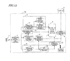
- FIGS. 12 and 13 are a block diagram illustrating an ultrasonic diagnostic apparatus as a third preferred embodiment of the present invention and a flowchart showing the typical procedure of operation according to the third preferred embodiment, respectively.
- the ultrasonic diagnostic apparatus 103 of the third preferred embodiment of the present invention includes the ultrasonic signal processing section 2, the tomographic image processing section 3, the vascular wall thickness calculating section 4, the pulsation detecting section 5, the reliability determining section 6, the control section 7, the image synthesizing section 8, a longitudinal axis determining section 20, a stability determining section 21 and the vascular center determining section 31.
- the apparatus of this preferred embodiment includes the longitudinal axis determining section 20 and the stability determining section 21 and that the reliability determining section 6 uses the results obtained by the longitudinal axis determining section 20 and the stability determining section 21.
- the probe 1 may be the same as what is used in the first preferred embodiment of the present invention described above.
- the ultrasonic signal processing section 2, the tomographic image processing section 3, the vascular center determining section 31, the vascular wall thickness calculating section 4 and the pulsation detecting section 5 perform the same processing as what has already been described for the first preferred embodiment.
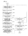
- processing steps S201, S202, S203 and S204 of this preferred embodiment may be respectively the same as the processing steps S101, S102, S103 and S104 of the first preferred embodiment described above.
- the tomographic image information provided by the tomographic image processing section 3 is also output to the longitudinal axis determining section 20.
- the longitudinal axis determining section 20 determines, based on the luminance information included in the tomographic image information, whether or not the tomographic image information being provided covers a longitudinal cross section of the blood vessel. In this processing step, if it has turned out, based on the luminance distribution of the tomographic image information in the IMT measuring range (see FIG. 18 ), that the image is being captured in the longitudinal direction of the blood vessel, then tomographic image information can be regarded as covering a longitudinal cross section of the blood vessel.
- the degree of probability that the tomographic image information covers a longitudinal cross section of the blood vessel may be determined instead of simply determining whether the longitudinal axis is covered or not.
- the stability determining section 21 calculates the magnitude of variation in the IMT value due to some disturbance such as the motion of the probe 1 or the subject, thereby determining the degrees of stability of the IMT value calculated.
- the time for the IMT calculating section 42 to calculate the IMT value is supposed to be the end-diastolic timing.
- the IMT value calculated by the IMT calculating section 42 is sent to the stability determining section 21 every cardiac cycle.
- the stability determining section 21 accumulates the IMT values calculated for a predetermined number of cardiac cycles. Then, the stability determining section 21 may compare the difference between the multiple IMT values accumulated to a predetermined value. And if the difference has turned out to be smaller than the predetermined value, the stability determining section 21 may decide that the IMT value calculated hardly varies in spite of the motion of the probe 1 or the subject and is sufficiently stabilized. Or the stability determining section 21 may also decide that the smaller the difference between the multiple IMT values accumulated, the more stabilized the IMT value calculated should be. In this manner, the stability determining section 21 may determine the degree of stability of the IMT value finely instead of just determining whether the IMT value calculated is a stabilized one or not.
- next two processing steps S205 and S206 of this preferred embodiment may be respectively the same as the processing steps S105 and S106 of the first preferred embodiment described above.
- the reliability determining section 6 determines the reliability of the IMT value that has been calculated by the IMT calculating section 42 based on (a) the result of the decision made by the longitudinal axis determining section 20, (b) the result of the decision made by the vascular center determining section 31, (c) the result of the pulsating status checkout made by the pulsating status checking section 52 based on the information provided by the pulsation information processing section 51 and the cardiac cycle detecting section 53, and (d) the result of the decision made by the stability determining section 21.
- Step S208 the reliability determining section 6 determines whether or not the IMT value obtained is reliable enough to use as the final result of measurement. If the answer is YES, the control section 7 decides in the next processing step S209 that this IMT value be defined as the result of measurement. Optionally, in this processing step, the processing of freezing the image may be carried out. On the other hand, if the reliability determining section 6 has not found the IMT value obtained reliable enough, then the process goes back to the processing step S201 to carry on the measurement.
- the reliability determining section 6 carries out its reliability determining processing.
- the reliability determining section 6 deciders that the IMT value obtained be a highly reliable one.
- the stability determining section 21 has decided that the magnitude of variation of the IMT value is smaller than a predetermined value and the IMT value is sufficiently stabilized as described above, then the reliability determining section 6 also decides that the IMT value obtained be a highly reliable one.
- the reliability determining section 6 also decides that the IMT value obtained be a highly reliable one. And if either all, or at least a predetermined number, of these four conditions (1) through (4) are satisfied, then the reliability determining section 6 decides that the IMT value obtained be reliable enough to use as the final result of measurement.
- the longitudinal axis determining section 20 may calculate an estimated value indicating the degree of probability that the tomographic image information provided covers a longitudinal cross section of the blood vessel as described above.
- the stability determining section 21 may calculate an estimated value indicating the degree of stability of the IMT value calculated as described above.
- the vascular center determining section 31 may calculate an estimated value indicating the probability that the probe 1 is put in a right position to catch the blood vessel close enough to its center.
- the pulsating status checking section 52 may calculate an estimated value indicating the probability that the pulse of the blood vessel is measured properly.
- the reliability determining section 6 may calculate an estimated value indicating the reliability of the IMT value obtained. And if the estimated value is beyond a predetermined reference value, then the reliability determining section 6 may decide that the IMT value obtained be reliable enough to use as the final result of measurement.
- Step S210 the image synthesizing section 8 synthesizes together the IMT measured value, which has been regarded as the final result of measurement in accordance with the decision made by the reliability determining section 6 , and the tomographic image that has been generated by the tomographic image processing section 3 and then outputs a synthetic image thus obtained to the display 9. Then, the operator can see, with his or her own eyes, whether or not the measurement can be carried out on a cross section of the blood vessel that passes its longitudinal center. As a result, the operator can confirm the result of measurement and its reliability on the screen. Consequently, the present invention contributes to increasing the operability significantly.
- the result of the decision made by the reliability determining section 6 may also be displayed by itself as characters or a symbol or icon instead of being synthesized with the tomographic image.
- those results of the decisions made by the longitudinal axis determining section 20, the vascular center determining section 31, the pulsating status checking section 52 and the stability determining section 21 may be presented on the display 9.
- those results of decision if the reliability of the IMT value obtained has turned out to be low, the user can know exactly why its reliability is low, thus contributing to increasing the operability.
- the longitudinal axis determining section 20 determines whether or not the tomographic image information provided covers a longitudinal cross section of the blood vessel and if the result of the decision is used to determine the reliability, it can be determined more accurately whether or not the received signal has been obtained from a cross section of the blood vessel that passes its longitudinal center. As a result, the IMT value obtained can be a more reliable one.
- the stability determining section 21 determines the degree of stability of the IMT value calculated based on its magnitude of variation and if the result of the decision is used to determine the reliability, then the IMT value that is hardly affected by the motion of the probe 1 or the subject can be defined as the final result of measurement. As a result, the IMT value obtained can be a more reliable one.
- the longitudinal axis determining section 20 determines, based on the tomographic image information provided by the tomographic image processing section 3, whether or not the tomographic image information covers a longitudinal cross section of the subject's blood vessel. However, this decision can also be made based on the amplitude of the received echo signal supplied from the ultrasonic signal processing section 2. Then, the decision can be made without depending on the settings or parameters used when the tomographic image is generated.
- the vascular center determining section 31 determines, based on the tomographic image information provided by the tomographic image processing section 3, whether or not the received signal has been obtained from a cross section of the blood vessel that passes its longitudinal center. However, this decision can also be made based on the amplitude of the received echo signal supplied from the ultrasonic signal processing section 2. Then, the decision can be made without depending on the settings or parameters used when the tomographic image is generated.
- the longitudinal axis determining processing step S211, the stability determining processing step S212, the vascular center determining processing step S205 and the pulsating status checkout processing step S206 are supposed to be performed in this order. However, these processing steps may also be performed in any other order.
- the apparatus of this preferred embodiment is supposed to include both the longitudinal axis determining section 20 and the stability determining section 21.
- the apparatus may include either only the longitudinal axis determining section 20 or only the stability determining section 21.
- FIGS. 14 and 15 are a block diagram illustrating an ultrasonic diagnostic apparatus as a fourth preferred embodiment of the present invention and a flowchart showing the typical procedure of operation according to the fourth preferred embodiment, respectively.
- the ultrasonic diagnostic apparatus 104 of the fourth preferred embodiment of the present invention includes the ultrasonic signal processing section 2, the tomographic image processing section 3, the vascular wall thickness calculating section 4, the pulsation detecting section 5, the reliability determining section 6, the control section 7, the image synthesizing section 8, the longitudinal axis determining section 20, the stability determining section 21, the vascular center determining section 31 and a decision criterion setting section 22.
- the apparatus 104 of this preferred embodiment includes a decision criterion setting section 22 that sets criteria of decision for the vascular center determination, the pulsating status checkout, the longitudinal axis determination and the stability determination so as to vary with the feature of the luminance signal in the ROI.
- the probe 1 may be the same as what is used in the first preferred embodiment of the present invention described above.
- the ultrasonic signal processing section 2, the tomographic image processing section 3, the vascular center determining section 31, the vascular wall thickness calculating section 4 and the pulsation detecting section 5 perform the same processing as what has already been described for the first preferred embodiment.
- the longitudinal axis determining section 20 and the stability determining section 21 perform the same processing as what has already been described for the third preferred embodiment.
- processing steps S301, S302, S303 and S304 of this preferred embodiment may be respectively the same as the processing steps S101, S102, S103 and S104 of the first preferred embodiment described above.
- the decision criterion setting section 22 In response to a control signal supplied as a trigger from the control section 7 in Step S313, the decision criterion setting section 22 calculates in the next processing step S314 a value representing the feature of a luminance signal around the boundaries based on the tomographic image information provided by the tomographic image processing section 3 and information about the boundaries detected by the boundary detecting section 41. And by changing predetermined values for use to make decisions in the longitudinal axis determining section 20, the stability determining section 21, the vascular center determining section 31 and the pulsating status checking section 52 according to this feature quantity, the decision criterion setting section 22 sets a criterion of decision.
- the next four processing steps S311, S312, S305 and S306 of this preferred embodiment may be respectively the same as the processing steps S211 and S212 of the third preferred embodiment described above and the processing steps S105 and S106 of the first preferred embodiment described above.
- Step S307 based on the decisions that have been made by the longitudinal axis determining section 20, the stability determining section 21, the vascular center determining section 31 and the pulsating status checking section 52 using the threshold value that has been set by the decision criterion setting section 22, the reliability determining section 6 determines the reliability of the IMT value obtained.
- the vascular center determination, pulsating status checkout, longitudinal axis determination and stability determination can be carried out according to the attribute of an individual subject's tissue, and therefore, the accuracy and reliability of the IMT value obtained can be increased.
- Step S308 the reliability determining section 6 determines whether or not the IMT value obtained is reliable enough to use as the final result of measurement. If the answer is YES, the control section 7 decides in the next processing step S309 that this IMT value be defined as the result of measurement. Optionally, in this processing step, the processing of freezing the image may be carried out. On the other hand, if the reliability determining section 6 has not found the IMT value obtained reliable enough, then the process goes back to the processing step S301 to carry on the measurement.
- the last processing step S310 may be the same as the processing step S210 of the third preferred embodiment described above.
- the control signal supplied from the control section 7 is supposed to be used as a trigger.
- the timing when the longitudinal axis determining section 20 decides that the tomographic image provided cover a longitudinal cross section of the blood vessel may also be used as a trigger. In that case, as soon as the tomographic image as viewed in the longitudinal direction has been obtained, the IMT measurement can be started smoothly.
- an input section may be provided and the user's input may also be used as a trigger. In that case, it is possible to have a user who knows very well about how to make an IMT measurement set the criterion of decision.
- the longitudinal axis determining processing step S311, the stability determining processing step S312, the vascular center determining processing step S305 and the pulsating status checkout processing step S306 are supposed to be performed in this order. However, these processing steps may also be performed in any other order.
- the apparatus of this preferred embodiment is supposed to include both the longitudinal axis determining section 20 and the stability determining section 21. However, the apparatus may include only one of them.
- FIG. 15 is a block diagram illustrating the ultrasonic diagnostic apparatus of the fifth preferred embodiment.
- any functional block also shown in FIG. 2 with the sane reference numeral has substantially the same function as its counterpart of the first preferred embodiment and description thereof will be omitted herein.
- a reliability determining section 60 determines the degree of reliability of the status monitored or the calculated value (i.e., how reliable the status or value is to use it as a result of measurement) based on the results of measurement or processing obtained by the tomographic image processing section 3, the vascular wall thickness calculating section 4 and the pulsation detecting section 5.
- a frame storage section 61 stores the degree of reliability that has been determined by the reliability determining section 60, along with the IMT value that has been calculated by the IMT calculating section 42 and the tomographic image that has been generated by the tomographic image processing section 3, as a frame.
- a best frame choosing section 62 chooses one frame with the highest degree of reliability from all or at least a subset of the frames that are stored in the frame storage section 61.
- a control section 70 not only controls the respective functional blocks but also performs a control based on the result of decision made by the reliability determining section 60 so that the result of measurement of the frame that has been chosen by the best frame choosing section 62 is used as the final result of measurement or that the image is frozen on the screen to display the result of measurement of the frame and the tomographic image thereon.
- the image synthesizing section 80 is designed so that the display 9 is connectible thereto, and synthesizes the result of measurement of the frame that has been chosen by the best frame choosing section and the tomographic image together so that their synthetic image can be presented on the display 9.
- FIG. 17 is a flowchart showing a typical procedure of operation of the fifth preferred embodiment of the present invention.
- the probe 1, the ultrasonic signal processing section 2, the tomographic image processing section 3, the vascular center determining section 31, the vascular wall thickness calculating section 4 including the boundary detecting section 41 and the IMT calculating section 42, and the best detecting section 5 including the pulsation information processing section 51 and the pulsating status checking section 52 operate in the same way as their counterparts of the first preferred embodiment described above.
- the processing steps S401, S402, S403, S404, S405 and S406 are respectively the same as the processing steps S101, S102, S103, S104, S105 and S106 of the first preferred embodiment described above.
- Step S407 the reliability determining section 60 examines the pulsating status that has been detected and checked by the vascular center determining section 31 and the pulsating status checking section 52, thereby determining the degree of reliability of the IMT value that has been calculated by the IMT calculating section 42. And the reliability determining section 60 determines the degree of reliability indicating how reliable the IMT value obtained is to use it as the result of measurement.
- the vascular center determining section 31 calculates an estimated value indicating the degree of probability that the probe 1 is put in a right position to catch the blood vessel around its center, while the pulsating status checking section 52 calculates an estimated value indicating the degree of probability that the pulse of the blood vessel is being measured properly.
- Step S415 the degree of reliability determined, as well as the IMT value that has been calculated by the IMT calculating section 42 and the tomographic image that has been generated by the topographic image processing section 3, is stored as a frame in the frame storage section 61.
- the processing step S416 will be described later.
- Step S417 in accordance with the instruction given by the control section 7, the best frame choosing section 62 retrieves the frames that are stored in the frame storage section 61 and chooses a frame with the highest degree of reliability from all or a subset of the frames. And the control section 7 decides that the IMT value of the chosen frame be defined as the IMT measured value.
- the timing when the control section 7 gives that instruction may be when the image is frozen by the control section 7 in accordance with the user's command or the decision made by the reliability determining section 60 as will be described later.
- the apparatus may be designed, as in Step S416, so that the reliability determining section 60 performs the processing of getting the image frozen by the control section 7 only when some conditions are satisfied.
- the image may be frozen when at least a certain number of frames, of which the degrees of reliability are higher than a predetermined value, are written in the frame storage section 61 or when the number, of such frames, of which the degrees of reliability are higher than a predetermined value and which have been written consecutively in the frame storage section 61, reaches a certain number.
- the best frame choosing section 62 preferably chooses a frame with the highest degree of reliability from those consecutive frames. If the condition for freezing is not satisfied, however, the process goes back to the processing step 401 to carry on the measurement.
- the vascular center determining processing step S405 and the pulsating status checkout processing step S406 are supposed to be performed in this order. However, these processing steps may be carried out in reverse order, too.
- the IMT measured value and a tomographic image representing the blood vessel can be reliable enough to use as the final result of measurement.
- the reliability determining section 60 can make the decision based on either only the result obtained by the vascular center determining section 31 or just the one obtained by the pulsating status checking section 52. If both of these two results are relied on, the accuracy of the decision can be increased. Nevertheless, depending on the situation of the inspection, the decision can also be made based on only of those two results. That is why the given software programs may be selectively used appropriately according to the application, cost and weight of the apparatus as in the first preferred embodiment described above.
- the ultrasonic diagnostic apparatus 105 may also be modified so as to further include the longitudinal axis determining section 20 and stability determining section 21 that have already been described for the third preferred embodiment of the present invention.
- the reliability determining section 60 will determine the degree of reliability of the IMT value that has been calculated by the IMT calculating section 42 based on not only the results obtained by the vascular center determining section 31 and the pulsating status checking section 52 but also the ones obtained by the longitudinal axis determining section 20 and the stability determining section 21 as well.
- the ultrasonic diagnostic apparatus 105 may also be modified so as to further include the decision criterion setting section 2 that has already been described for the fourth preferred embodiment of the present invention.
- the apparatus may be designed to set the criterion of decision by changing the predetermined values for use to make decisions in the longitudinal axis determining section 20, the stability determining section 21, the vascular center determining section 31 and the pulsating status checking section 52 in response to the control signal supplied from the control section 7 as a trigger.
- the decision criterion setting section 22 will operate in the same way, and will achieve the same effects, as in the fourth preferred embodiment described above, and description thereof will be omitted herein.
- Step S410 the image synthesizing section 80 synthesizes together the IMT measured value of the frame that has been chosen by the best frame choosing section 62 in accordance with the decision made by the reliability determining section 60 and the tomographic image, and then outputs the synthetic image thus obtained to the display 9.
- the operator can monitor the diagnostic image and the result of measurement on the screen.
- the pulsation detecting section 5 of this ultrasonic diagnostic apparatus may also be replaced with the pulsation detecting section 50 of the second preferred embodiment that uses the ECG pads 12.
- the difference between this preferred embodiment shown in FIG. 16 and that alternative preferred embodiment and their respective features are the same as the relation between the first and second preferred embodiments of the present invention, and a detailed description thereof will be omitted herein.
- the present invention provides an ultrasonic diagnostic apparatus that can achieve not only the effect of getting the IMT value measured more easily with increased operability but also the effect of measuring the IMT more accurately as well while making an inspection.
- the ultrasonic diagnostic apparatus and intima-media thickness (IMT) measuring method of the present invention it is determined whether the blood vessel that is the object of IMT measurement is inspected in an appropriate state (e.g., whether the probe is put in a right position) and at the best timing. And the IMT value that has been obtained at such timing is used as the final result of measurement.
- the IMT measured value can be a highly reliable one, thus contributing to significantly increasing the accuracy and operability of the inspection of arterial sclerosis, for example. Consequently, the present invention is effectively applicable to an ultrasonic diagnostic apparatus and a method for measuring an IMT using such an apparatus.
Landscapes
- Health & Medical Sciences (AREA)
- Life Sciences & Earth Sciences (AREA)
- Engineering & Computer Science (AREA)
- Medical Informatics (AREA)
- Biophysics (AREA)
- Nuclear Medicine, Radiotherapy & Molecular Imaging (AREA)
- Pathology (AREA)
- Radiology & Medical Imaging (AREA)
- Veterinary Medicine (AREA)
- Biomedical Technology (AREA)
- Heart & Thoracic Surgery (AREA)
- Physics & Mathematics (AREA)
- Molecular Biology (AREA)
- Surgery (AREA)
- Animal Behavior & Ethology (AREA)
- General Health & Medical Sciences (AREA)
- Public Health (AREA)
- Vascular Medicine (AREA)
- Ultra Sonic Daignosis Equipment (AREA)
Applications Claiming Priority (2)
| Application Number | Priority Date | Filing Date | Title |
|---|---|---|---|
| JP2010027246 | 2010-02-10 | ||
| PCT/JP2010/006661 WO2011099103A1 (ja) | 2010-02-10 | 2010-11-12 | 超音波診断装置および内中膜複合体厚の測定方法 |
Publications (2)
| Publication Number | Publication Date |
|---|---|
| EP2535005A1 true EP2535005A1 (de) | 2012-12-19 |
| EP2535005A4 EP2535005A4 (de) | 2015-08-19 |
Family
ID=44367417
Family Applications (1)
| Application Number | Title | Priority Date | Filing Date |
|---|---|---|---|
| EP10845708.6A Withdrawn EP2535005A4 (de) | 2010-02-10 | 2010-11-12 | Ultraschalldiagnosevorrichtung und intima-media-komplexdicke-messverfahren dafür |
Country Status (5)
| Country | Link |
|---|---|
| US (1) | US9179889B2 (de) |
| EP (1) | EP2535005A4 (de) |
| JP (1) | JP5754379B2 (de) |
| CN (1) | CN102469987B (de) |
| WO (1) | WO2011099103A1 (de) |
Families Citing this family (31)
| Publication number | Priority date | Publication date | Assignee | Title |
|---|---|---|---|---|
| JP5972569B2 (ja) * | 2011-12-26 | 2016-08-17 | 東芝メディカルシステムズ株式会社 | 超音波診断装置、超音波画像処置装置、医用画像診断装置及び超音波画像処理プログラム |
| WO2013124946A1 (ja) * | 2012-02-20 | 2013-08-29 | 株式会社デンソー | 生体の血管径連続測定装置 |
| JP5844175B2 (ja) * | 2012-02-20 | 2016-01-13 | 富士フイルム株式会社 | 超音波診断装置および超音波画像生成方法 |
| CN102800089B (zh) * | 2012-06-28 | 2015-01-28 | 华中科技大学 | 基于颈部超声图像的主颈动脉血管提取和厚度测量方法 |
| US20140039319A1 (en) * | 2012-08-06 | 2014-02-06 | Seiko Epson Corporation | Ultrasonic measuring apparatus and blood vessel inner diameter calculating method |
| US9746322B2 (en) | 2012-09-10 | 2017-08-29 | Furuno Electric Co., Ltd. | Thickness measuring device and thickness measuring method |
| JP5859946B2 (ja) * | 2012-10-30 | 2016-02-16 | ジーイー・メディカル・システムズ・グローバル・テクノロジー・カンパニー・エルエルシー | 計測装置及びその制御プログラム |
| JP5859950B2 (ja) | 2012-11-29 | 2016-02-16 | ジーイー・メディカル・システムズ・グローバル・テクノロジー・カンパニー・エルエルシー | 計測装置及びその制御プログラム |
| US10646198B2 (en) * | 2015-05-17 | 2020-05-12 | Lightlab Imaging, Inc. | Intravascular imaging and guide catheter detection methods and systems |
| JP6544092B2 (ja) * | 2015-07-08 | 2019-07-17 | 国立大学法人東京農工大学 | 血管径測定装置 |
| CN106570871B (zh) * | 2016-11-02 | 2019-10-18 | 天津大学 | 模糊c均值颈动脉超声图像内中膜厚度测量方法及系统 |
| KR102687099B1 (ko) | 2017-01-23 | 2024-07-19 | 나이키 이노베이트 씨.브이. | 멀티 코일 스캐닝을 갖는 무선 충전 시스템 |
| CN111225619B (zh) * | 2017-10-17 | 2023-04-04 | 富士胶片株式会社 | 声波诊断装置及声波诊断装置的控制方法 |
| EP3749215A4 (de) | 2018-02-07 | 2021-12-01 | Atherosys, Inc. | Vorrichtung und verfahren zur steuerung der ultraschallaufnahme der peripheren arterien in der transversalen ebene |
| EP3787480A4 (de) | 2018-04-30 | 2022-01-26 | Atherosys, Inc. | Verfahren und vorrichtung zur automatischen detektion von atheromen in peripheren arterien |
| US11759166B2 (en) | 2019-09-20 | 2023-09-19 | Bard Access Systems, Inc. | Automatic vessel detection tools and methods |
| JP7457566B2 (ja) * | 2020-04-30 | 2024-03-28 | 富士フイルムヘルスケア株式会社 | 超音波診断装置、臍帯長測定方法及びプログラム |
| CN216135922U (zh) | 2020-09-08 | 2022-03-29 | 巴德阿克塞斯系统股份有限公司 | 动态调整超声成像系统 |
| CN114159098B (zh) | 2020-09-10 | 2026-01-02 | 巴德阿克塞斯系统股份有限公司 | 具有压力测量能力的超声探测器 |
| EP4247267A1 (de) | 2020-11-24 | 2023-09-27 | Bard Access Systems, Inc. | Ultraschallsystem mit ziel- und medizinischem instrumentenbewusstsein |
| CN114569155A (zh) | 2020-12-01 | 2022-06-03 | 巴德阿克塞斯系统股份有限公司 | 超声成像系统和用于通过其获得超声图像的方法 |
| WO2022119856A1 (en) | 2020-12-01 | 2022-06-09 | Bard Access Systems, Inc. | Ultrasound system with pressure and flow determination capability |
| WO2022141083A1 (zh) * | 2020-12-29 | 2022-07-07 | 深圳迈瑞生物医疗电子股份有限公司 | 周期性参数的分析方法和超声成像系统 |
| CN217960146U (zh) | 2021-04-15 | 2022-12-06 | 巴德阿克塞斯系统股份有限公司 | 超声成像系统 |
| JP7694317B2 (ja) * | 2021-10-04 | 2025-06-18 | コニカミノルタ株式会社 | 超音波診断装置、超音波診断装置の制御方法、及び、超音波診断装置の制御プログラム |
| US12376817B2 (en) | 2021-11-03 | 2025-08-05 | Bard Access Systems, Inc. | Optimized functionality through interoperation of doppler and image based vessel differentiation |
| US12419607B2 (en) * | 2021-12-22 | 2025-09-23 | Philips Image Guided Therapy Corporation | Intraluminal imaging for reference image frame and target image frame confirmation with deep breathing |
| JP7815783B2 (ja) * | 2022-01-19 | 2026-02-18 | セイコーエプソン株式会社 | 厚み算出方法、厚み算出プログラム、及び厚み算出装置 |
| US12514532B2 (en) | 2022-03-01 | 2026-01-06 | Bard Access Systems, Inc. | Ultrasound imaging system |
| US12514533B2 (en) | 2022-03-01 | 2026-01-06 | Bard Access Systems, Inc. | Ultrasound imaging system |
| EP4489661B1 (de) * | 2022-03-16 | 2025-10-29 | Bard Access Systems, Inc. | Ultraschallbildgebungssystem |
Family Cites Families (20)
| Publication number | Priority date | Publication date | Assignee | Title |
|---|---|---|---|---|
| JP2889568B1 (ja) * | 1998-05-18 | 1999-05-10 | 正男 伊藤 | 血管膜厚測定装置及び動脈硬化診断装置 |
| JP4240633B2 (ja) | 1999-02-10 | 2009-03-18 | 株式会社東芝 | 超音波ドプラ診断装置 |
| JP4263943B2 (ja) * | 2003-05-07 | 2009-05-13 | テルモ株式会社 | 超音波診断装置 |
| DE602004030242D1 (de) | 2003-05-20 | 2011-01-05 | Panasonic Corp | Ultraschallgerät |
| US7569016B2 (en) | 2003-07-03 | 2009-08-04 | Panasonic Corporation | Ultrasonic diagnostic apparatus |
| CN1845707B (zh) * | 2003-09-01 | 2010-04-28 | 松下电器产业株式会社 | 生物体信号监视装置 |
| EP1806099A4 (de) * | 2004-10-19 | 2007-12-12 | Matsushita Electric Industrial Co Ltd | Ultraschallgerät und ultraschallgerät-kontrollverfahren |
| JP2006122295A (ja) * | 2004-10-28 | 2006-05-18 | Matsushita Electric Ind Co Ltd | 超音波診断装置 |
| US20090163811A1 (en) * | 2006-03-20 | 2009-06-25 | Matsushita Electric Industrial Co., Ltd. | Ultrasonograph |
| CN101505664B (zh) * | 2006-08-21 | 2011-08-31 | 国立大学法人东北大学 | 超声波诊断装置 |
| ITPI20060105A1 (it) * | 2006-08-28 | 2008-02-29 | C N R Consiglio Naz Delle Ricerche | Apparecchiatura per la localizzazione automatica delle interfacce lume-intima e media-avventizia in un vaso sanguigno. |
| WO2008038615A1 (en) * | 2006-09-25 | 2008-04-03 | Tohoku University | Ultrasonographic device |
| JP5230106B2 (ja) | 2007-01-15 | 2013-07-10 | 富士フイルム株式会社 | 超音波診断装置、imt計測方法及びimt計測プログラム |
| JP5346440B2 (ja) * | 2007-02-15 | 2013-11-20 | 富士フイルム株式会社 | 超音波診断装置及びデータ計測プログラム |
| JP2009039277A (ja) * | 2007-08-08 | 2009-02-26 | Panasonic Corp | 超音波診断装置 |
| JP5014051B2 (ja) * | 2007-10-09 | 2012-08-29 | 株式会社ユネクス | 血管超音波画像測定方法 |
| JP2009153573A (ja) | 2007-12-25 | 2009-07-16 | Panasonic Corp | 超音波診断装置および断層画像処理方法 |
| JP5249327B2 (ja) | 2008-07-01 | 2013-07-31 | パナソニック株式会社 | 超音波診断装置 |
| JP5166154B2 (ja) * | 2008-07-18 | 2013-03-21 | 富士フイルム株式会社 | 超音波診断装置 |
| US9826959B2 (en) * | 2008-11-04 | 2017-11-28 | Fujifilm Corporation | Ultrasonic diagnostic device |
-
2010
- 2010-11-12 JP JP2011553665A patent/JP5754379B2/ja not_active Expired - Fee Related
- 2010-11-12 CN CN201080036008.3A patent/CN102469987B/zh not_active Expired - Fee Related
- 2010-11-12 EP EP10845708.6A patent/EP2535005A4/de not_active Withdrawn
- 2010-11-12 WO PCT/JP2010/006661 patent/WO2011099103A1/ja not_active Ceased
- 2010-11-12 US US13/496,832 patent/US9179889B2/en not_active Expired - Fee Related
Non-Patent Citations (1)
| Title |
|---|
| See references of WO2011099103A1 * |
Also Published As
| Publication number | Publication date |
|---|---|
| CN102469987B (zh) | 2015-11-25 |
| CN102469987A (zh) | 2012-05-23 |
| JPWO2011099103A1 (ja) | 2013-06-13 |
| WO2011099103A1 (ja) | 2011-08-18 |
| US20120179042A1 (en) | 2012-07-12 |
| EP2535005A4 (de) | 2015-08-19 |
| US9179889B2 (en) | 2015-11-10 |
| JP5754379B2 (ja) | 2015-07-29 |
Similar Documents
| Publication | Publication Date | Title |
|---|---|---|
| US9179889B2 (en) | Ultrasonic diagnostic device, and method for measuring initma-media complex thickness | |
| US9826959B2 (en) | Ultrasonic diagnostic device | |
| JP5501999B2 (ja) | 超音波診断装置および弾性指標信頼性判定方法 | |
| JP5823312B2 (ja) | 超音波撮像システムの作動方法 | |
| JP4602972B2 (ja) | 超音波診断装置および超音波診断装置の制御方法 | |
| WO2018134726A1 (en) | Method and apparatus to characterise non-invasively images containing venous blood vessels | |
| US20100063391A1 (en) | Ultrasonograph | |
| EP2656792A1 (de) | Ultraschalldiagnosevorrichtung und steuerverfahren für die ultraschalldiagnosevorrichtung | |
| JPWO2009013871A1 (ja) | 超音波診断装置 | |
| JP4667394B2 (ja) | 超音波診断装置 | |
| WO2009013686A2 (en) | Systems and methods for automated image selection in doppler ultrasound imaging systems | |
| EP2719334A1 (de) | Ultraschalldiagnosevorrichtung und ultraschallmessverfahren damit | |
| JP5015513B2 (ja) | 解剖学的構造の計測のための一体型超音波デバイス | |
| WO2014030174A2 (en) | Automated evaluation of arterial stiffness for a non-invasive screening | |
| JP5346555B2 (ja) | 動脈硬化リスク表示機能を備えた超音波診断装置 | |
| JP4667392B2 (ja) | 超音波診断装置 | |
| JP2009039277A (ja) | 超音波診断装置 | |
| JP2012016508A (ja) | 超音波診断装置及び信号解析プログラム | |
| JP2011019993A (ja) | 超音波診断装置、超音波画像処理装置、及び超音波信号処理プログラム | |
| Guerreschi et al. | A new method to determine arterial distensibility in small arteries |
Legal Events
| Date | Code | Title | Description |
|---|---|---|---|
| PUAI | Public reference made under article 153(3) epc to a published international application that has entered the european phase |
Free format text: ORIGINAL CODE: 0009012 |
|
| 17P | Request for examination filed |
Effective date: 20120613 |
|
| AK | Designated contracting states |
Kind code of ref document: A1 Designated state(s): AL AT BE BG CH CY CZ DE DK EE ES FI FR GB GR HR HU IE IS IT LI LT LU LV MC MK MT NL NO PL PT RO RS SE SI SK SM TR |
|
| DAX | Request for extension of the european patent (deleted) | ||
| RAP1 | Party data changed (applicant data changed or rights of an application transferred) |
Owner name: KONICA MINOLTA, INC. |
|
| RA4 | Supplementary search report drawn up and despatched (corrected) |
Effective date: 20150717 |
|
| RIC1 | Information provided on ipc code assigned before grant |
Ipc: A61B 8/06 20060101AFI20150713BHEP |
|
| STAA | Information on the status of an ep patent application or granted ep patent |
Free format text: STATUS: THE APPLICATION HAS BEEN WITHDRAWN |
|
| 18W | Application withdrawn |
Effective date: 20150828 |