EP2535280A2 - Procédé destiné à distribuer des étiquettes placées sur une bande de support et procédé de fabrication de bandes de support équipées d'étiquettes - Google Patents
Procédé destiné à distribuer des étiquettes placées sur une bande de support et procédé de fabrication de bandes de support équipées d'étiquettes Download PDFInfo
- Publication number
- EP2535280A2 EP2535280A2 EP12168658A EP12168658A EP2535280A2 EP 2535280 A2 EP2535280 A2 EP 2535280A2 EP 12168658 A EP12168658 A EP 12168658A EP 12168658 A EP12168658 A EP 12168658A EP 2535280 A2 EP2535280 A2 EP 2535280A2
- Authority
- EP
- European Patent Office
- Prior art keywords
- labels
- web
- carrier tape
- label
- carrier
- Prior art date
- Legal status (The legal status is an assumption and is not a legal conclusion. Google has not performed a legal analysis and makes no representation as to the accuracy of the status listed.)
- Withdrawn
Links
- 238000000034 method Methods 0.000 title claims description 68
- 238000004519 manufacturing process Methods 0.000 title claims description 16
- 239000000853 adhesive Substances 0.000 claims description 71
- 230000001070 adhesive effect Effects 0.000 claims description 67
- 239000000463 material Substances 0.000 claims description 60
- 238000006243 chemical reaction Methods 0.000 claims description 26
- 230000000181 anti-adherent effect Effects 0.000 claims description 14
- 230000002093 peripheral effect Effects 0.000 claims description 2
- 238000002360 preparation method Methods 0.000 claims description 2
- 238000004080 punching Methods 0.000 description 19
- 238000007639 printing Methods 0.000 description 16
- 238000002372 labelling Methods 0.000 description 14
- 239000004820 Pressure-sensitive adhesive Substances 0.000 description 10
- 239000000203 mixture Substances 0.000 description 10
- -1 polyethylene Polymers 0.000 description 10
- 239000012943 hotmelt Substances 0.000 description 9
- 238000000576 coating method Methods 0.000 description 8
- 238000004804 winding Methods 0.000 description 8
- 238000011161 development Methods 0.000 description 7
- 230000018109 developmental process Effects 0.000 description 7
- 239000010410 layer Substances 0.000 description 7
- NIXOWILDQLNWCW-UHFFFAOYSA-M Acrylate Chemical compound [O-]C(=O)C=C NIXOWILDQLNWCW-UHFFFAOYSA-M 0.000 description 6
- 239000011248 coating agent Substances 0.000 description 6
- 239000011159 matrix material Substances 0.000 description 6
- 229920005989 resin Polymers 0.000 description 6
- 239000011347 resin Substances 0.000 description 6
- 238000003860 storage Methods 0.000 description 6
- 239000004743 Polypropylene Substances 0.000 description 5
- 239000002131 composite material Substances 0.000 description 5
- 238000004132 cross linking Methods 0.000 description 5
- 239000011888 foil Substances 0.000 description 5
- 238000010030 laminating Methods 0.000 description 5
- 229920001296 polysiloxane Polymers 0.000 description 5
- 230000008901 benefit Effects 0.000 description 4
- 230000005540 biological transmission Effects 0.000 description 4
- 229920001155 polypropylene Polymers 0.000 description 4
- GWEVSGVZZGPLCZ-UHFFFAOYSA-N Titan oxide Chemical compound O=[Ti]=O GWEVSGVZZGPLCZ-UHFFFAOYSA-N 0.000 description 3
- XLOMVQKBTHCTTD-UHFFFAOYSA-N Zinc monoxide Chemical compound [Zn]=O XLOMVQKBTHCTTD-UHFFFAOYSA-N 0.000 description 3
- 150000001252 acrylic acid derivatives Chemical class 0.000 description 3
- 239000000654 additive Substances 0.000 description 3
- 239000003054 catalyst Substances 0.000 description 3
- 230000006870 function Effects 0.000 description 3
- 238000004806 packaging method and process Methods 0.000 description 3
- 239000004033 plastic Substances 0.000 description 3
- 229920003023 plastic Polymers 0.000 description 3
- 229920000642 polymer Polymers 0.000 description 3
- 229920000098 polyolefin Polymers 0.000 description 3
- GRWFGVWFFZKLTI-IUCAKERBSA-N (-)-α-pinene Chemical compound CC1=CC[C@@H]2C(C)(C)[C@H]1C2 GRWFGVWFFZKLTI-IUCAKERBSA-N 0.000 description 2
- 229920005789 ACRONAL® acrylic binder Polymers 0.000 description 2
- RSWGJHLUYNHPMX-UHFFFAOYSA-N Abietic-Saeure Natural products C12CCC(C(C)C)=CC2=CCC2C1(C)CCCC2(C)C(O)=O RSWGJHLUYNHPMX-UHFFFAOYSA-N 0.000 description 2
- 229920002799 BoPET Polymers 0.000 description 2
- 244000043261 Hevea brasiliensis Species 0.000 description 2
- KHPCPRHQVVSZAH-HUOMCSJISA-N Rosin Natural products O(C/C=C/c1ccccc1)[C@H]1[C@H](O)[C@@H](O)[C@@H](O)[C@@H](CO)O1 KHPCPRHQVVSZAH-HUOMCSJISA-N 0.000 description 2
- VYPSYNLAJGMNEJ-UHFFFAOYSA-N Silicium dioxide Chemical compound O=[Si]=O VYPSYNLAJGMNEJ-UHFFFAOYSA-N 0.000 description 2
- 239000006096 absorbing agent Substances 0.000 description 2
- 238000010521 absorption reaction Methods 0.000 description 2
- 239000012790 adhesive layer Substances 0.000 description 2
- 239000004840 adhesive resin Substances 0.000 description 2
- 229920006223 adhesive resin Polymers 0.000 description 2
- 150000001412 amines Chemical class 0.000 description 2
- 239000003963 antioxidant agent Substances 0.000 description 2
- ISAOCJYIOMOJEB-UHFFFAOYSA-N benzoin Chemical class C=1C=CC=CC=1C(O)C(=O)C1=CC=CC=C1 ISAOCJYIOMOJEB-UHFFFAOYSA-N 0.000 description 2
- 230000008033 biological extinction Effects 0.000 description 2
- 238000007766 curtain coating Methods 0.000 description 2
- 238000005034 decoration Methods 0.000 description 2
- 239000000945 filler Substances 0.000 description 2
- 238000006459 hydrosilylation reaction Methods 0.000 description 2
- 230000010354 integration Effects 0.000 description 2
- 239000007788 liquid Substances 0.000 description 2
- 229920003052 natural elastomer Polymers 0.000 description 2
- 229920001194 natural rubber Polymers 0.000 description 2
- 239000004014 plasticizer Substances 0.000 description 2
- 229920001083 polybutene Polymers 0.000 description 2
- 229920000728 polyester Polymers 0.000 description 2
- 229920000139 polyethylene terephthalate Polymers 0.000 description 2
- 239000005020 polyethylene terephthalate Substances 0.000 description 2
- 230000005855 radiation Effects 0.000 description 2
- 238000007650 screen-printing Methods 0.000 description 2
- 238000000926 separation method Methods 0.000 description 2
- 229920006268 silicone film Polymers 0.000 description 2
- 239000007787 solid Substances 0.000 description 2
- 230000003068 static effect Effects 0.000 description 2
- 239000000758 substrate Substances 0.000 description 2
- 229920003051 synthetic elastomer Polymers 0.000 description 2
- 239000005061 synthetic rubber Substances 0.000 description 2
- 150000003568 thioethers Chemical class 0.000 description 2
- KHPCPRHQVVSZAH-UHFFFAOYSA-N trans-cinnamyl beta-D-glucopyranoside Natural products OC1C(O)C(O)C(CO)OC1OCC=CC1=CC=CC=C1 KHPCPRHQVVSZAH-UHFFFAOYSA-N 0.000 description 2
- 238000002834 transmittance Methods 0.000 description 2
- WTARULDDTDQWMU-RKDXNWHRSA-N (+)-β-pinene Chemical compound C1[C@H]2C(C)(C)[C@@H]1CCC2=C WTARULDDTDQWMU-RKDXNWHRSA-N 0.000 description 1
- WTARULDDTDQWMU-IUCAKERBSA-N (-)-Nopinene Natural products C1[C@@H]2C(C)(C)[C@H]1CCC2=C WTARULDDTDQWMU-IUCAKERBSA-N 0.000 description 1
- MSMAPCFQRXQMRL-UHFFFAOYSA-N (2-oxo-1,2-diphenylethyl) prop-2-enoate Chemical compound C=1C=CC=CC=1C(OC(=O)C=C)C(=O)C1=CC=CC=C1 MSMAPCFQRXQMRL-UHFFFAOYSA-N 0.000 description 1
- HECLRDQVFMWTQS-RGOKHQFPSA-N 1755-01-7 Chemical compound C1[C@H]2[C@@H]3CC=C[C@@H]3[C@@H]1C=C2 HECLRDQVFMWTQS-RGOKHQFPSA-N 0.000 description 1
- SMZOUWXMTYCWNB-UHFFFAOYSA-N 2-(2-methoxy-5-methylphenyl)ethanamine Chemical compound COC1=CC=C(C)C=C1CCN SMZOUWXMTYCWNB-UHFFFAOYSA-N 0.000 description 1
- NIXOWILDQLNWCW-UHFFFAOYSA-N 2-Propenoic acid Natural products OC(=O)C=C NIXOWILDQLNWCW-UHFFFAOYSA-N 0.000 description 1
- NEFZIZUSNPOFFC-UHFFFAOYSA-N 2-hydroxy-1,2-diphenylethanone;2-methylprop-2-enoic acid Chemical compound CC(=C)C(O)=O.C=1C=CC=CC=1C(O)C(=O)C1=CC=CC=C1 NEFZIZUSNPOFFC-UHFFFAOYSA-N 0.000 description 1
- 241001136792 Alle Species 0.000 description 1
- VGGSQFUCUMXWEO-UHFFFAOYSA-N Ethene Chemical compound C=C VGGSQFUCUMXWEO-UHFFFAOYSA-N 0.000 description 1
- 239000005977 Ethylene Substances 0.000 description 1
- 239000013032 Hydrocarbon resin Substances 0.000 description 1
- 239000006057 Non-nutritive feed additive Substances 0.000 description 1
- ISWSIDIOOBJBQZ-UHFFFAOYSA-N Phenol Chemical compound OC1=CC=CC=C1 ISWSIDIOOBJBQZ-UHFFFAOYSA-N 0.000 description 1
- 239000004952 Polyamide Substances 0.000 description 1
- 239000004698 Polyethylene Substances 0.000 description 1
- WTARULDDTDQWMU-UHFFFAOYSA-N Pseudopinene Natural products C1C2C(C)(C)C1CCC2=C WTARULDDTDQWMU-UHFFFAOYSA-N 0.000 description 1
- 229910000831 Steel Inorganic materials 0.000 description 1
- 230000006750 UV protection Effects 0.000 description 1
- ISKQADXMHQSTHK-UHFFFAOYSA-N [4-(aminomethyl)phenyl]methanamine Chemical compound NCC1=CC=C(CN)C=C1 ISKQADXMHQSTHK-UHFFFAOYSA-N 0.000 description 1
- 229920005700 acResin® Polymers 0.000 description 1
- 239000008186 active pharmaceutical agent Substances 0.000 description 1
- 238000013006 addition curing Methods 0.000 description 1
- 239000002313 adhesive film Substances 0.000 description 1
- 230000032683 aging Effects 0.000 description 1
- XCPQUQHBVVXMRQ-UHFFFAOYSA-N alpha-Fenchene Natural products C1CC2C(=C)CC1C2(C)C XCPQUQHBVVXMRQ-UHFFFAOYSA-N 0.000 description 1
- MVNCAPSFBDBCGF-UHFFFAOYSA-N alpha-pinene Natural products CC1=CCC23C1CC2C3(C)C MVNCAPSFBDBCGF-UHFFFAOYSA-N 0.000 description 1
- 229930006722 beta-pinene Natural products 0.000 description 1
- 235000013361 beverage Nutrition 0.000 description 1
- 229920006378 biaxially oriented polypropylene Polymers 0.000 description 1
- 239000011127 biaxially oriented polypropylene Substances 0.000 description 1
- 230000000903 blocking effect Effects 0.000 description 1
- QXJJQWWVWRCVQT-UHFFFAOYSA-K calcium;sodium;phosphate Chemical compound [Na+].[Ca+2].[O-]P([O-])([O-])=O QXJJQWWVWRCVQT-UHFFFAOYSA-K 0.000 description 1
- 239000006229 carbon black Substances 0.000 description 1
- 239000012876 carrier material Substances 0.000 description 1
- 238000004140 cleaning Methods 0.000 description 1
- 150000001875 compounds Chemical class 0.000 description 1
- 238000009833 condensation Methods 0.000 description 1
- 230000005494 condensation Effects 0.000 description 1
- 229920001577 copolymer Polymers 0.000 description 1
- 239000002537 cosmetic Substances 0.000 description 1
- 239000003431 cross linking reagent Substances 0.000 description 1
- 230000006735 deficit Effects 0.000 description 1
- 230000032798 delamination Effects 0.000 description 1
- 230000001419 dependent effect Effects 0.000 description 1
- 230000000994 depressogenic effect Effects 0.000 description 1
- 239000003599 detergent Substances 0.000 description 1
- 238000010017 direct printing Methods 0.000 description 1
- 239000006185 dispersion Substances 0.000 description 1
- 229920001971 elastomer Polymers 0.000 description 1
- 230000005611 electricity Effects 0.000 description 1
- 238000005516 engineering process Methods 0.000 description 1
- 238000001125 extrusion Methods 0.000 description 1
- 230000002550 fecal effect Effects 0.000 description 1
- 239000000835 fiber Substances 0.000 description 1
- 238000005429 filling process Methods 0.000 description 1
- 235000013305 food Nutrition 0.000 description 1
- LCWMKIHBLJLORW-UHFFFAOYSA-N gamma-carene Natural products C1CC(=C)CC2C(C)(C)C21 LCWMKIHBLJLORW-UHFFFAOYSA-N 0.000 description 1
- 229920006270 hydrocarbon resin Polymers 0.000 description 1
- 239000004611 light stabiliser Substances 0.000 description 1
- 229940087305 limonene Drugs 0.000 description 1
- 239000000314 lubricant Substances 0.000 description 1
- 239000000155 melt Substances 0.000 description 1
- 125000005395 methacrylic acid group Chemical group 0.000 description 1
- 239000000178 monomer Substances 0.000 description 1
- 239000003921 oil Substances 0.000 description 1
- 230000003287 optical effect Effects 0.000 description 1
- 238000005457 optimization Methods 0.000 description 1
- 239000005022 packaging material Substances 0.000 description 1
- 150000002989 phenols Chemical class 0.000 description 1
- AQSJGOWTSHOLKH-UHFFFAOYSA-N phosphite(3-) Chemical class [O-]P([O-])[O-] AQSJGOWTSHOLKH-UHFFFAOYSA-N 0.000 description 1
- OJMIONKXNSYLSR-UHFFFAOYSA-N phosphorous acid Chemical compound OP(O)O OJMIONKXNSYLSR-UHFFFAOYSA-N 0.000 description 1
- 229920002647 polyamide Polymers 0.000 description 1
- 229920000515 polycarbonate Polymers 0.000 description 1
- 239000004417 polycarbonate Substances 0.000 description 1
- 229920006267 polyester film Polymers 0.000 description 1
- 229920000573 polyethylene Polymers 0.000 description 1
- 229920006324 polyoxymethylene Polymers 0.000 description 1
- 229920000346 polystyrene-polyisoprene block-polystyrene Polymers 0.000 description 1
- 150000003097 polyterpenes Chemical class 0.000 description 1
- 230000004224 protection Effects 0.000 description 1
- GRWFGVWFFZKLTI-UHFFFAOYSA-N rac-alpha-Pinene Natural products CC1=CCC2C(C)(C)C1C2 GRWFGVWFFZKLTI-UHFFFAOYSA-N 0.000 description 1
- 239000002516 radical scavenger Substances 0.000 description 1
- 239000005060 rubber Substances 0.000 description 1
- 238000007665 sagging Methods 0.000 description 1
- 150000004760 silicates Chemical class 0.000 description 1
- 239000000377 silicon dioxide Substances 0.000 description 1
- 239000002904 solvent Substances 0.000 description 1
- 239000003381 stabilizer Substances 0.000 description 1
- 239000010959 steel Substances 0.000 description 1
- 239000000126 substance Substances 0.000 description 1
- 230000003746 surface roughness Effects 0.000 description 1
- 150000003606 tin compounds Chemical class 0.000 description 1
- 239000004408 titanium dioxide Substances 0.000 description 1
- 239000012780 transparent material Substances 0.000 description 1
- 229920002554 vinyl polymer Polymers 0.000 description 1
- 238000004383 yellowing Methods 0.000 description 1
- 239000011787 zinc oxide Substances 0.000 description 1
Images




Classifications
-
- B—PERFORMING OPERATIONS; TRANSPORTING
- B65—CONVEYING; PACKING; STORING; HANDLING THIN OR FILAMENTARY MATERIAL
- B65C—LABELLING OR TAGGING MACHINES, APPARATUS, OR PROCESSES
- B65C9/00—Details of labelling machines or apparatus
- B65C9/0006—Removing backing sheets
-
- B—PERFORMING OPERATIONS; TRANSPORTING
- B65—CONVEYING; PACKING; STORING; HANDLING THIN OR FILAMENTARY MATERIAL
- B65C—LABELLING OR TAGGING MACHINES, APPARATUS, OR PROCESSES
- B65C9/00—Details of labelling machines or apparatus
- B65C9/08—Label feeding
- B65C9/18—Label feeding from strips, e.g. from rolls
- B65C9/1865—Label feeding from strips, e.g. from rolls the labels adhering on a backing strip
Definitions
- the invention relates to methods for dispensing existing on a carrier tape labels, wherein the labels are arranged on the top and the bottom of the carrier tape in each case in a row behind each other, and method for producing such carrier tapes.
- Conventional self-adhesive labels which are further processed as roll material, are produced from a carrier label material which is coated on one side with a pressure-sensitive adhesive which is covered with an adhesive (also known as anti-adhesive or dehesive) carrier tape.
- the carrier tape has the function to fix the diecuts and to transport in the printing press, so that a label roll in the form of an Archimedean spiral with individual, arranged in a row behind the other Label diecuts are created.
- the carrier tape has the task of enabling further processing of the labels, in which the diecuts are removed from the carrier tape by a dispensing edge during labeling and adhered to the product.
- the dispensing edge is usually a tapered sheet, in which the tip is rounded in a small radius, for example 3 mm.
- the carrier tape (release paper, release film) is not part of the label, but only an aid for their production, storage or for further processing by Punching.
- the carrier tape is not firmly bonded to the adhesive layer.
- Abhesive coatings are widely used to make the described carrier tapes by applying a coating to sheet materials such as papers or films to reduce the adhesion tendency of adherend products to these surfaces.
- the carrier tape must be removable from the label. By the carrier tape itself or by the removal of the carrier tape, the adhesive power of the PSA should not be significantly affected for later use.
- the stability of the anti-adhesive coating (also referred to as a release coating) on the carrier tape, ie the abhesiveness, over long periods of time is important in order to ensure the function of this coating and the properties of the pressure-sensitive adhesive covered with the liner.
- the carrier tape usually a silicone paper or a silicone film used, initially serves the stated purposes and must be disposed of after labeling, so after all labels are removed.
- the carrier tape contributes a significant share of the label costs, it sometimes makes up half of the material content. In addition, costs arise through transport, storage and disposal of the carrier tape.
- labels are applied to both sides (ie, the top and bottom sides) of a double-sided anti-adhesive backing tape.
- half of the carrier tape is saved, which reduces both the label costs (resources) and follow-up costs through transport, storage and disposal of the carrier tape.
- a roll made of a carrier web equipped with labels on both sides offers space for 25% more labels.
- a label composite is used, consisting of a double-sided anti-adhesive equipped carrier tape on which are applied on both sides webs of label material, which are provided with adhesive. Furthermore, the label material is successively punched from both sides therein, which is less advantageous because thus the carrier tape can be injured from both sides due to variations in the thickness of the opposing web and its adhesive.
- the opposite label web is pulled off and guided around the punching work, so that there is no risk for this first punching, as described above, to damage the carrier tape.
- the second label material is then fed again, so that during the following punching of this second path such damage can take place by punching the carrier tape.
- the contour in the second punching is within that of the first punching on the opposite side.
- the object of the present invention is to provide methods by which labels which are arranged one behind the other on the upper side and the underside of a carrier tape can be dispensed reliably and with high efficiency, and methods by which a carrier tape can be produced the Labels on the top and the bottom are each arranged in a row one behind the other.
- the invention relates to a method for dispensing existing on a carrier tape labels, wherein the labels are arranged on the top and the bottom of the carrier tape in each case in a row one behind the other.
- the carrier tape is guided in the direction of a dispensing edge with the labels applied on the top and bottom side.
- the labels are removed on the top or the bottom by a transfer device of the carrier web and received by the conversion device.
- the carrier web is then guided over a dispensing edge in such a way that the side of the carrier web is in direct contact with the dispensing edge, on which there are no labels.
- the labels located on the carrier web are dispensed at the dispensing edge.
- the invention thus describes a process-reliable method for labeling label rolls with labels on both sides of a carrier, which can be integrated into existing labeling equipment and wherein the dispensing operation is carried out by means of conventional dispensing edges.
- FIG. 1 This advantageous embodiment of the invention is disclosed in FIG. 1 shown.
- the label roll (2) with punched labels (3 and 4), which are located on the upper and the lower side of the carrier tape (5), in the development (1) is first unwound and guided direction donation edge (6).
- the carrier web (5) via a transfer device (7, 8) is guided, in which the labels (4) with the non-adhesive top of the conversion device (7, 8) and thus removed from the carrier web (5) are removed.
- the labels are fixed on the transfer device (7, 8) and transported by the transfer device (7, 8), while the carrier web (5), only equipped with the labels (3) on the upper side, via a take-off device, for example a Roller (9), removed from the conversion device (7, 8) and further towards the dispensing edge (6) is guided.
- a take-off device for example a Roller (9
- dispensing on the upper side of the carrier tape (5) located labels (3) via a conventional dispensing edge (6) wherein the execution of the dispensing edge (6) are varied and any known and common dispensing edge can be used.
- the dispensing edge (6) in the form of a pointed wedge, wherein the carrier tape (5) is guided over the top. This is preferably rounded, more preferably with a radius of 3 mm.
- the labels (4) located on the conversion device (7, 8) are again laminated onto the carrier strip (5).
- the conversion device (7, 8) instead of a preferred roller (7) by a moving conveyor belt (8) are formed.
- any differently shaped, for example, curved moving transport aids fulfill the same function, namely to receive the labels, to fix and continue to transport.
- the labels (4) located on the conversion device (7, 8) preferably have no contact with the carrier tape (5) in the period after removal from the carrier tape (5) until re-laying on the carrier tape (5).
- the labels (4) located on the transfer device (7, 8) are in contact with the carrier tape (5) at the point where they are removed and with the carrier tape (5) at the point where they are reloaded become. In this way, a secure guidance of the labels (4) in the conversion device (7, 8) is possible.
- the peripheral speed of the conversion device (7, 8) corresponds to the web speed of the carrier tape (5) to ensure a tension-free removal and placing the labels (4) on the carrier tape (5).
- the conversion device (7, 8) is a driven roller (7).
- the labels (4) in the conversion device (7, 8) cover.
- the labels (4) are not applied again at exactly the same location of the carrier tape (5) but slightly offset, in particular by one to two centimeters in the machine direction.
- the conversion device (7, 8) preferably a roller (7) or a conveyor belt (8), provided with a vacuum or vacuum device, which generates a negative pressure or a vacuum in the interior of the conversion device (7, 8) the labels (4) located on the outer surface of the transfer device (7, 8) can be fixed.
- it is a perforated or porous cylinder, in which a negative pressure is applied inside, so that the labels thereon are sucked and adhere to the cylinder.
- the conversion device (7, 8) for removing the labels (4) from the carrier tape and their further transport on the conversion device (7, 8) (as mentioned preferably on a cylinder (7) or a belt (8)) in addition to the preferred negative pressure (or in addition to) also other methods available.
- adhesion to labels (4) is ensured from films by static charging, with the labels (4) are charged and thus adhere to the conveyor belt (8) or the cylinder (7).
- the label material should be chosen so that the best possible adhesion can be achieved by static electricity.
- self-adhering materials may be used, such as adhesive films or conveyor belts or cylinder surfaces made of adhesive or blocking plastic materials.
- adhesive films or conveyor belts or cylinder surfaces made of adhesive or blocking plastic materials.
- plastics are known and are used for example for cleaning film webs in printing machines or for the protection of surfaces.
- the detachment of the labels (4) from the carrier web (5) is preferably effected by means of a roller (9) over which the carrier web (5) is guided while the labels (4) remain in the transfer device (7, 8). Damage to the labels (3) on the other side of the carrier web (5) is thus avoided.
- Advantageous are small roll diameters up to 6 mm or 3 mm in diameter. In order to prevent sagging of the roller (9) at small diameters, these can optionally be supported by larger rollers located behind it. These can, as in FIG. 8 can be seen, if necessary, also cascade-like consist of several rollers, which are arranged with larger diameters behind the roller (9) for support.
- the labels After the transfer of the labels (4) on the transport cylinder (7) or the conveyor belt (8), the labels must remain fixed on this position (10). This is done by means of the above-mentioned methods, preferably negative pressure or electrostatics, self-adhesive plastics or the like.
- the carrier web (5) is wound with the Careaufgespendeten labels (4) to a roll in a winder (12), which can later be re-supplied to this or another dispensing process.
- the roll In the second dispensing operation, the roll can be clamped the other way around in the development (1). It goes through the same path.
- This embodiment of the invention is not optimized insofar as that for the dispensing of all labels an additional roll change and thus an additional work during the labeling process are required. Also, if necessary, at the end of production, there are two remaining rolls in processing (1) and (12) in the event that the roll in processing (1) has not been used completely.
- the inventive method is further developed so that the entire roll (2) with the located on the upper side and on the lower side of the carrier tape labels (3, 4) can be labeled in one operation.
- the label web must be turned beforehand by means of a conventional web turning device (16). Subsequently, the labels (4) are applied with a conventional dispensing edge, as they have already been explained in detail above. Subsequently, the empty carrier tape (5) is wound in a winding (13).
- labels (3, 4) are brought to the dispensing edge with the carrier web.
- the carrier tape (5) stops until the item to be labeled is in the appropriate position.
- the carrier tape (5) moves on for the labeling process again.
- the speed is usually above the speed of the goods.
- the carrier tape (5) moves discontinuously in a continuous start / stop cycle.
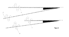
- the carrier tape (5) when the donation process is used, as the FIG. 3 shows, it is desirable that the carrier tape (5) also runs continuously over as long a distance as possible at a constant speed. Only in the region of the dispensing edge (6, 15) should the carrier tape (5) have a discontinuous movement.
- FIG. 4 shown material stores (17), which provide for a decoupling of the carrier tape (5) in the region of the dispensing edges (6, 15) from the rest of the carrier tape (5).
- the carrier tape (5) is continuously guided from the left towards the upper dispensing edge (6). If the carrier tape (5) at the dispensing edge (6) just stand still, the carrier tape (5) is guided into the first memory and the fast propulsion of the carrier tape (5) at the dispensing edge (6) retrieved from this again.
- the second memory (17) which operates so that after the dispensing operation discontinuously running carrier tape (5) is fed back into the system at a continuous speed.
- the two lower material storage (17) work on the same principle.
- FIG. 5 An alternative embodiment of the invention shows FIG. 5 , With this variant, all labels (3, 4) can be used on the label roll (2), without additional additional expenditure due to a roll change of the roll, which has arisen in the winding (12) from the carrier web (5) provided with the labels (4).
- the role (2) is based on the processing (1) - as in FIG. 1 described - unwound, with which all on the upper side of the carrier tape (5) located labels (3) are dispensed, and at the same time in the reel (12) wound with the remaining labels (4).
- the carrier web (5) from the winding (12) by means of a roller (18) the end of the carrier web (5), which results from the almost complete unwinding of the label roll (2) on the unwinding (1), and glued to it to form a splice, while at the same time the carrier web (5) is severed before the splice.
- the carrier web (5) has to stop for a short time over the entire run length, which is achieved by using material stores (17), analogous to those in FIG. 4 shown, can be supported. This applies in particular to the area before and after the splice to be formed.
- the winding (12) is for unwinding, the carrier strip (5) remaining after the second dispensing is fed to a second winding (19).
- either two labels (3, 4) of the same type, which are applied on both sides of the carrier tape (5), can be dispensed on a label roll (2).
- the donation process can be as described in Figure 1 to 5 respectively.
- Advantage in the method, as in FIG. 3 it is shown that the efficiency of donation with two donor edges (6, 15) can be increased.
- different labels may also be applied on both sides of the carrier tape (5), preferably those which are needed on both sides of a packaging material, for example a bottle or a crucible become.
- a packaging material for example a bottle or a crucible become.
- FIG. 1 For dispensing this set is in FIG. 1 presented method only limited.
- the automatic roll change according to FIG. 5 is not applicable here.
- the method is for this purpose FIG. 3 very good usable with appropriate material storage, as in FIG. 4 are shown.
- the second part of this invention describes preferred methods for making label webs with labels on both sides of a carrier tape.
- the second punch preferably consists of a punching roller, which punches the second label web through the adhesive, and a counterpressure roller.
- the punching roller is anti-adhesive equipped.
- the counter-pressure roller consists of a porous or perforated cylinder to fix the labels via vacuum on the counter-pressure roller.
- the web (21) is punched in a conventional manner (23), wherein as in FIG. 6 shown the web (21) is punched from below and therefore first by means of a turning cross (36) is turned. Subsequently, the punched web (21) is diverted and passed under a second punching unit (30). According to the invention this can also be done in the opposite way, in which the web is not turned, punched from above and passed over the subsequent punching. Furthermore, from a second development (25) another label web (28) unwound, in which it is a label material, also called printing material (film or paper) is, which is not initially provided with adhesive. As described for the first web (21), this second web (28) can also be printed in a further printing device (27).
- a label material also called printing material (film or paper)
- the material web (28) is provided in an application station (29) with adhesive, as shown in the EP 1 321 919 A1 and EP 1 818 893 A1 is described.
- adhesive as shown in the EP 1 321 919 A1 and EP 1 818 893 A1 is described.
- slot dies particularly those in the curtain coating method or by means of a roller stick nozzle, in order to achieve an adhesive application in no-label-look quality (no-label labels are printed, transparent adhesive labels which have the impression on the smooth surface direct printing, the adhesive must be highly transparent and without any structures).
- hotmelts in particular UV acrylates or those of synthetic rubber, polyolefin adhesive or the like, are used as adhesives for this purpose.
- the printed web is punched in a punching device (30) without being previously laminated to the first web (21).
- the punching is done according to FIG. 6 also from below. Since an adhesive material is punched, the punching tool (30) must be anti-adhesive equipped.
- a porous or perforated cylinder (31) is used for this purpose.
- the label web with the matrix ie the material in the spaces between the diecuts, transported by the impression cylinder (31), or it is already removed at this point this matrix, and only the labels themselves remain on the impression cylinder (31) adhere
- a negative pressure is applied, but preferably only in the region of the cylinder, which is looped by the material web (28).
- the web is discharged via a further roller (33), wherein in the nip - formed from counter-pressure cylinder (31) and roller (33), the laminating point at which transfer the labels from the second web (28) on the web (21) become.
- additional compressed air can be employed at the laminating point, so that the labels are loosened better.
- the fixation of the labels and the further transport can be carried out on this up to the fecal point by means of electrostatics, as already at earlier point in FIG. 1 is described. All methods described there as possibilities can also be used according to the invention for this purpose. From the laminated web (34) before the winding (35) nor the above-described matrix (37), the punched grid, optionally removed from both label webs.
- FIG. 7 describes a further preferred method for producing label webs with labels on both sides of a carrier web.
- a web is used, consisting of a backing sheet (40), which is anti-adhesive on both sides, and a label web (39), consisting of a label material equipped with an adhesive.
- the development (38) can be part of a label printing machine.
- the web is printed using the usual printing methods such as offset, book, gravure, flexo or screen printing in a printing device (41).
- printing methods such as offset, book, gravure, flexo or screen printing in a printing device (41).
- all other methods such as hot or cold foil stamping, inkjet or digital printing are available for decoration.
- this stamped label web is fed to a transfer device (43), the stamped web (45) being separated from the carrier web (56).
- a conversion device (43) is preferably a porous or perforated cylinder (43) use to fix the labels on the cylinder (43).
- a porous or perforated cylinder (43) use to fix the labels on the cylinder (43).
- the label web with the matrix so the material in the spaces between the diecuts, transported by the cylinder (43), or it is already at this point (or before) this matrix removed, and only the labels themselves remain on the cylinder (43).
- a negative pressure is applied, but preferably only in the region of the cylinder (43), which is wrapped by the material web.
- the web is removed via another roller (53), wherein in the nip - formed from cylinder (43) and roller (53), the laminating point at which the labels from the web (39) are transferred to the web (40) ,
- additional compressed air can be employed at the laminating point, so that the labels are loosened better.
- the fixation of the labels and the further transport on this up to the laminating point (53) also take place by means of electrostatics, as already at FIG. 1 is described. All methods described there as possibilities can also be used according to the invention for this purpose.
- a further label material (47) is unwound, which is a substrate (foil or paper), which is not provided with adhesive. As described for the first material web, this web can also be printed (48). If necessary, the web is turned (49), depending on whether you want to generate a counter or frontal pressure. Subsequently, the material web is provided in another application station (5) with adhesive, as shown in the EP 1 321 919 A1 and the EP 1 818 893 A1 is described. It can do this the usual commissioned works are used.
- slot dies are particularly preferred, those in the curtain coating method or by means of a roller bar nozzle in order to achieve an adhesive application in no-label-look quality.
- hotmelts are used as adhesives, in particular UV acrylates or those of synthetic rubber, polyolefin adhesive or the like.
- the printed web is laminated onto the carrier web (56) originating from the other label web (39) (51).
- this label composite is punched in the usual way (from below).
- the punched web of the conversion device (43) is supplied and laminated with an added roller (53).
- the now existing composite of two stamped label materials, which are each provided with an adhesive, which are applied to a double-sided anti-adhesive carrier tape, is rolled up in a winding (55).
- the matrix described above is removed with, for example, a conventional grid winding (54) of both label webs, unless this has already taken place at an earlier point after the punching.
- the carrier web of the label can be selected from papers or various films; in particular, said transparent films are preferred.
- Biaxially oriented polypropylene is characterized by its very high tensile strength and low elongation.
- Preferred for the production of the labels are biaxially oriented films based on polypropylene.
- the thicknesses of the biaxially oriented films based on polypropylene are preferably between 20 and 100 ⁇ m, in particular between 25 and 75 ⁇ m, very particularly between 30 and 65 ⁇ m.
- Biaxially oriented films based on polypropylene can be produced by blown film extrusion or by means of conventional flat film systems. Biaxially stretched films are produced in one or more layers. In the case of multilayer films, the thickness and composition of the different layers may be the same, but also different thicknesses and compositions are known.
- Suitable for the labels are monolayered, biaxially or monoaxially stretched films or multilayered, biaxial or monoaxial polypropylene based films which have a sufficiently strong bond between the layers since delamination of the layers during use is disadvantageous.
- Films based on rigid PVC are used for the production of labels as well as films based on soft PVC.
- Foils based on rigid PVC can also be used for the labels.
- the thicknesses of the films are preferably between 20 and 100 ⁇ m, in particular between 25 and 65 ⁇ m, very particularly between 30 and 60 ⁇ m.
- Polyester-based films for example polyethylene terephthalate, are also known and can also be used to make the labels.
- the thicknesses of the films based on PET are between 20 and 100 ⁇ m, in particular between 25 and 65 ⁇ m, very particularly between 30 and 60 ⁇ m.
- the labels are preferably equipped with a pressure-sensitive adhesive.
- Adhesive adhesives are adhesives which, even under relatively slight pressure, permit a permanent bond with the primer and, after use, in the Substantially residue-free from the primer can be replaced again.
- Pressure-sensitive adhesives are permanently tacky at room temperature and therefore have a sufficiently low viscosity and high tack, so that they wet the surface of the respective adhesive base even at low pressure. The adhesiveness of the adhesives is based on their adhesive properties and the removability on their cohesive properties.
- the labels may contain as pressure-sensitive adhesive one which is applied to the carrier as an aqueous dispersion adhesive or as a solvent-containing system. Preference is given according to the invention hotmelts, including those which are cured after application from the melt with UV radiation.
- the adhesive can be applied over the entire surface or adapted to the particular application partially.
- the PSA is preferably one based on natural rubber, PUR or acrylates or may contain styrene-isoprene-styrene block copolymers.
- a pressure sensitive adhesive is a viscoelastic composition that remains permanently tacky and tacky at room temperature in a dry state. The bonding takes place by light pressure immediately on almost all substrates.
- Suitable masses are for example in the " Handbook of Pressure Sensitive Adhesive Technology ", second edition, edited by Donatas Satas, Van Nostrand Reinhold, New York, 1989 described.
- the self-adhesive composition used is in particular a commercially available pressure-sensitive adhesive composition based on PUR, acrylate or rubber, preferably a UV-crosslinkable acrylate hot-melt pressure-sensitive adhesive mixed with additives and resins.
- the Adhesive Novarad RC 21151 from Novamelt is an example.
- an acrylate hot melt base which has a K value of at least 20, in particular greater than 30, obtainable by concentrating a solution of such a composition into a system which can be processed as a hotmelt.
- benzoin derivatives may be copolymerized, such as benzoin acrylate or benzoin methacrylate, acrylic acid or Methacrylic esters. Such benzoin derivatives are in the EP 0 578 151 A1 described.
- the adhesive on Acrylathotmeltbasis can also be chemically crosslinked.
- An adhesive which is suitable is a low molecular weight acrylate hot melt pressure-sensitive adhesive, such as that marketed under the name acResin UV or Acronal®, in particular Acronal DS 3458, by BASF.
- This adhesive with a low K value obtains its application-oriented properties through a final radiation-induced crosslinking.
- Adhesive resins serve as tackifiers.
- Suitable tackifier resins include, inter alia, preferably nonhydrogenated, partially or fully hydrogenated resins based on rosin or rosin derivatives, hydrogenated polymers of dicyclopentadiene, non-hydrogenated, partially, selectively or completely hydrogenated hydrocarbon resins based on C 5 , C 5 / C 9 or C 9 monomer streams, or polyterpene resins based on ⁇ -pinene and / or ⁇ -pinene and / or ⁇ -limonene.
- the aforementioned adhesive resins can be used both alone and in admixture.
- Both solid and liquid resins can be used at room temperature.
- the adhesive application is preferably between 5.0 and 50.0 g / m 2 , more preferably between 10.0 and 30.0 g / m 2 and particularly preferably between 15.0 and 25.0 g / m 2 .
- the latter corresponds to a thickness between 15 and 25 microns.
- a double-sided siliconized PET film can be used, preferably with a thickness of 30 microns, for example, the silicone film Silphan S30 M74F from Siliconature.
- a suitable release liner carrier materials of various film materials such as PP each with a preferred thickness between 20.0 and 50.0 microns conceivable and common release papers.
- crosslinkable silicone systems are often used. These include mixtures of crosslinking catalysts and so-called thermally curable condensation or addition-crosslinking polysiloxanes.
- condensation-crosslinking silicone systems tin compounds, such as dibutyltin diacetate, are frequently present in the composition as crosslinking catalysts.
- Silicone-based release coatings on an addition-curing basis can be hardened by hydrosilylation.
- These separation systems usually include the following components: an alkenylated polydiorganosiloxane (especially alkenyl-terminated linear polymers), a polyorganohydrogensiloxane crosslinking agent, and a hydrosilylation catalyst.
- the labels may be circular, for example, with a diameter of 30 mm, oval, square or rectangular and square, the latter may also have rounded corners beyond.
- the outer shape of the labels can be varied almost unrestrictedly adapted to the respective application.
- the label material and the adhesive layer thereon are transparent.
- the transparency or the transmittance of an object depends on its extinction coefficient, the reflection on the surfaces as well as the Wavelength of the light used for the examination.
- the extinction coefficient is substance-specific and depends on the absorption of the material used. In order to obtain a material with a high transmittance, both absorption and reflection must be avoided.
- the reflection occurs at all interfaces and thus reduces the transmission coefficient of an object.
- n 2 1.6
- the maximum achievable transmission of a polyester film with a refractive index n 2 1.6, taking into account that the light steel obeys Fresnel's reflection law both when entering the film and exiting the film, does not reach a value of 90% exceed.
- both the adhesive and the label material are transparent in such a way that the transparent label formed therefrom preferably has a transmission of greater than 60%, in particular a transmission greater than 90% at a wavelength of 350 to 1150 nm.
- the processes according to the invention are particularly advantageously used for visually appealing labels which can be used, for example, on cosmetic packaging.
- an acrylate hotmelt composition is used, which, unlike other adhesives, is highly transparent and, because of its UV resistance, does not age as quickly as, for example, natural rubber compositions. That is, the label remains unchanged for a long time, in particular, does not discolor the adhesive (it does not occur the typical yellowing of the adhesive).
- acrylate hotmelt compound is very insensitive to many fillers, which are later filled into the packaging provided with the labels. That is, should the contents unintentionally, which is the case in particular during later use of the packaging, come into contact with the label, this does not mean that the adhesive of the label deteriorates in its adhesive performance and the label virtually "swim" on the package "begins.
- Such labels are furthermore preferably suitable for the labeling of containers from the detergents and cleaners industry, from the lubricant industry as well as for the beverage or food industry, generally wherever labels are needed in large quantities and must be applied at high speeds. Due to the large number of uses, almost any label material (films, paper, composite materials) in any desired coloration (transparent, white or colored) comes into question. Depending on the application, high value is placed on the optical properties of the adhesive with regard to transparency and resistances or else inexpensive adhesives are used, in particular if the label material is opaque.
Landscapes
- Making Paper Articles (AREA)
- Labeling Devices (AREA)
Applications Claiming Priority (1)
| Application Number | Priority Date | Filing Date | Title |
|---|---|---|---|
| DE102011076552A DE102011076552A1 (de) | 2011-05-26 | 2011-05-26 | Verfahren zum Verspenden von auf einem Trägerband vorhandenen Etiketten und Verfahren zur Herstellung von mit Etiketten ausgerüsteten Trägerbändern |
Publications (2)
| Publication Number | Publication Date |
|---|---|
| EP2535280A2 true EP2535280A2 (fr) | 2012-12-19 |
| EP2535280A3 EP2535280A3 (fr) | 2013-03-13 |
Family
ID=46125285
Family Applications (1)
| Application Number | Title | Priority Date | Filing Date |
|---|---|---|---|
| EP12168658A Withdrawn EP2535280A3 (fr) | 2011-05-26 | 2012-05-21 | Procédé destiné à distribuer des étiquettes placées sur une bande de support et procédé de fabrication de bandes de support équipées d'étiquettes |
Country Status (2)
| Country | Link |
|---|---|
| EP (1) | EP2535280A3 (fr) |
| DE (1) | DE102011076552A1 (fr) |
Cited By (1)
| Publication number | Priority date | Publication date | Assignee | Title |
|---|---|---|---|---|
| EP3103637A1 (fr) * | 2015-06-10 | 2016-12-14 | UPM Raflatac Oy | Étiquette imprimable comprenant une couche de face transparente et une couche adhésive transparente |
Citations (6)
| Publication number | Priority date | Publication date | Assignee | Title |
|---|---|---|---|---|
| DE2212995A1 (de) | 1972-03-17 | 1973-09-27 | Schaefer Etiketten | Verfahren und vorrichtung zum herstellen und ausgeben von selbstklebeetiketten |
| EP0578151A1 (fr) | 1992-07-08 | 1994-01-12 | Beiersdorf Aktiengesellschaft | Adhésifs thermofusibles sensibles à la pression pour des produits médicaux |
| DE4313008C1 (de) | 1993-04-21 | 1994-11-10 | Beiersdorf Ag | Selbstklebemasse auf Acrylathotmelt-Basis, Verfahren zu deren Herstellung und deren Verwendung |
| EP1321919A2 (fr) | 2001-12-21 | 2003-06-25 | tesa AG | Etiquette auto-adhesive, méthode de fabrication et son utilisation |
| DE60312458T2 (de) | 2002-11-14 | 2007-11-29 | L'oreal | Verfahren zur Herstellung eines Etikettenträgers |
| US20080017303A1 (en) | 2006-07-19 | 2008-01-24 | Crouch Tarquin L | Method and device for high speed labeling of articles using two-sided labelstock |
Family Cites Families (13)
| Publication number | Priority date | Publication date | Assignee | Title |
|---|---|---|---|---|
| GB653195A (en) * | 1948-07-13 | 1951-05-09 | Frank Philip Bossom | Making self adhesive labels |
| JPS5333400B2 (fr) * | 1973-11-16 | 1978-09-13 | ||
| US3938698A (en) * | 1974-11-27 | 1976-02-17 | Avery Products Corporation | Apparatus for dispensing adhesive labels |
| DE3511717C2 (de) * | 1985-03-29 | 1987-04-30 | Emmerich 7024 Filderstadt Benkowitsch | Verfahren und Vorrichtung zum Herstellen eines Trägerbandes mit darauf lösbar haftenden Selbstklebeetiketten |
| GB2235177A (en) * | 1989-08-21 | 1991-02-27 | Osaka Sealing Label Print | Method of producing a release web bearing adhesive labels |
| US5143466A (en) * | 1990-11-02 | 1992-09-01 | Strategic Financial Communications Corp. | Notebook page with pressure-sensitive repositionable labels on both sides thereof |
| JPH04126272U (ja) * | 1991-05-09 | 1992-11-17 | 日立マクセル株式会社 | ラベル |
| JPH0633173U (ja) * | 1992-09-30 | 1994-04-28 | トッパン・ムーア株式会社 | ラベルシート |
| FR2789972B1 (fr) * | 1999-02-18 | 2001-06-01 | Oreal | Procede d'alimentation d'un poste d'etiquetage et support d'etiquettes |
| EP1055604A1 (fr) * | 1999-05-18 | 2000-11-29 | CCL Label, Inc. | Dispositif et procédé pour découper des étiquettes d'une bande à étiquette adhérant sur une bande support et appliquer ces étiquettes |
| JP4400974B2 (ja) * | 1999-12-28 | 2010-01-20 | 株式会社サトー | ラベル連続体の送り孔加工方法及び装置 |
| JP3602786B2 (ja) * | 2000-11-10 | 2004-12-15 | 東亜機工株式会社 | ラベル貼付方法およびラベル貼付装置 |
| DE202005013883U1 (de) * | 2005-09-01 | 2005-11-24 | Schekulin, Karl, Prof. Dipl.-Ing. | Vorrichtung zum Etikettieren beidseitig angebrachter Etiketten auf dem Trägermaterial |
-
2011
- 2011-05-26 DE DE102011076552A patent/DE102011076552A1/de not_active Withdrawn
-
2012
- 2012-05-21 EP EP12168658A patent/EP2535280A3/fr not_active Withdrawn
Patent Citations (7)
| Publication number | Priority date | Publication date | Assignee | Title |
|---|---|---|---|---|
| DE2212995A1 (de) | 1972-03-17 | 1973-09-27 | Schaefer Etiketten | Verfahren und vorrichtung zum herstellen und ausgeben von selbstklebeetiketten |
| EP0578151A1 (fr) | 1992-07-08 | 1994-01-12 | Beiersdorf Aktiengesellschaft | Adhésifs thermofusibles sensibles à la pression pour des produits médicaux |
| DE4313008C1 (de) | 1993-04-21 | 1994-11-10 | Beiersdorf Ag | Selbstklebemasse auf Acrylathotmelt-Basis, Verfahren zu deren Herstellung und deren Verwendung |
| EP1321919A2 (fr) | 2001-12-21 | 2003-06-25 | tesa AG | Etiquette auto-adhesive, méthode de fabrication et son utilisation |
| EP1818893A1 (fr) | 2001-12-21 | 2007-08-15 | Tesa AG | Etiquette auto-adhesive, méthode de fabrication et son utilisation |
| DE60312458T2 (de) | 2002-11-14 | 2007-11-29 | L'oreal | Verfahren zur Herstellung eines Etikettenträgers |
| US20080017303A1 (en) | 2006-07-19 | 2008-01-24 | Crouch Tarquin L | Method and device for high speed labeling of articles using two-sided labelstock |
Non-Patent Citations (1)
| Title |
|---|
| "Handbook of pressure sensitive adhesive technology, second edition", 1989, VAN NOSTRAND REINHOLD |
Cited By (3)
| Publication number | Priority date | Publication date | Assignee | Title |
|---|---|---|---|---|
| EP3103637A1 (fr) * | 2015-06-10 | 2016-12-14 | UPM Raflatac Oy | Étiquette imprimable comprenant une couche de face transparente et une couche adhésive transparente |
| US9809730B2 (en) | 2015-06-10 | 2017-11-07 | Upm Raflatac Oy | Printable label comprising a clear face layer and a clear adhesive layer |
| US10233359B2 (en) | 2015-06-10 | 2019-03-19 | Upm Raflatac Oy | Method for labeling items with labels comprising a clear face layer and a clear adhesive layer |
Also Published As
| Publication number | Publication date |
|---|---|
| DE102011076552A1 (de) | 2012-11-29 |
| EP2535280A3 (fr) | 2013-03-13 |
Similar Documents
| Publication | Publication Date | Title |
|---|---|---|
| EP1113059B1 (fr) | Ruban adhésif inviolable pour emballage | |
| DE60301334T2 (de) | Klebstoffbeschichtetes dünnfilmetikett | |
| DE69837773T2 (de) | Verfahren zur Herstellung eines Laminats und daraus hergestellte Gegenstände | |
| EP1297090B1 (fr) | Bande adhesive de securite permettant de detecter l'ouverture non autorisee d'un emballage | |
| EP1113058B1 (fr) | Ruban adhésif inviolable pour emballage | |
| EP3616186B1 (fr) | Étiquette adhésive activable | |
| DE102012200831A1 (de) | Rundumetikett zur Etikettierung eines Gebindes wie einer Getränkeverpackung | |
| DE10030555A1 (de) | Sicherheitsklebeband zum Nachweis des unbefugten Öffnens einer Verpackung | |
| WO2015132410A1 (fr) | Matériau en rouleau pour une couche submicrométrique ou pourvu d'une couche submicrométrique sur un support flexible et utilisation dudit matériau | |
| EP2284095B1 (fr) | Emballage doté d'une ouverture prédécoupée pouvant être ouverte et fermée de manière réversible, et son procédé de fabrication | |
| EP1403190B1 (fr) | Sceau de garantie | |
| DE212013000198U1 (de) | Linerless-Etikettenbahn und Etikett | |
| DE102015205935A1 (de) | Leicht entfernbares Etikett ohne Trennfolie insbesondere für Mehrwegbehälter | |
| DE10022002A1 (de) | Sicherheitsklebeband zum Nachweis des unbefugten Öffnens einer Verpackung | |
| DE10030556A1 (de) | Sicherheitsklebeband zum Nachweis des unbefugten Öffnens einer Verpackung | |
| EP3173452B1 (fr) | Bande adhésive et son utilisation | |
| EP1666554B1 (fr) | Bande de sécurité pour détecter l'ouverture non autorisée d'emballage | |
| EP2535280A2 (fr) | Procédé destiné à distribuer des étiquettes placées sur une bande de support et procédé de fabrication de bandes de support équipées d'étiquettes | |
| EP1367107B1 (fr) | Utilisation d'un ruban adhésif comme ruban de masquage pour les opérations de peinture | |
| EP1233046B1 (fr) | Revêtement détachable comportant un ruban adhésif double face, et son utilisation dans une étiqueteuse à main | |
| DE102009043362A1 (de) | Etikettenstapel und Verfahren zum Aufbringen von Selbstklebeetiketten an Produktbehältern | |
| DE10247597A1 (de) | Release-Folie | |
| EP1367108B1 (fr) | Ruban adhésif déchirable comprenant un support déchirable à la main | |
| DE102005057932A1 (de) | Rolle einer Etikettenbahn in Form einer archimedischen Spirale aus hintereinander angeordneten Etiketten | |
| EP2794283A1 (fr) | Procédé de production d'un support d'impression |
Legal Events
| Date | Code | Title | Description |
|---|---|---|---|
| PUAI | Public reference made under article 153(3) epc to a published international application that has entered the european phase |
Free format text: ORIGINAL CODE: 0009012 |
|
| AK | Designated contracting states |
Kind code of ref document: A2 Designated state(s): AL AT BE BG CH CY CZ DE DK EE ES FI FR GB GR HR HU IE IS IT LI LT LU LV MC MK MT NL NO PL PT RO RS SE SI SK SM TR |
|
| AX | Request for extension of the european patent |
Extension state: BA ME |
|
| PUAL | Search report despatched |
Free format text: ORIGINAL CODE: 0009013 |
|
| PUAF | Information related to the publication of a search report (a3 document) modified or deleted |
Free format text: ORIGINAL CODE: 0009199SEPU |
|
| PUAL | Search report despatched |
Free format text: ORIGINAL CODE: 0009013 |
|
| AK | Designated contracting states |
Kind code of ref document: A3 Designated state(s): AL AT BE BG CH CY CZ DE DK EE ES FI FR GB GR HR HU IE IS IT LI LT LU LV MC MK MT NL NO PL PT RO RS SE SI SK SM TR |
|
| AX | Request for extension of the european patent |
Extension state: BA ME |
|
| RIC1 | Information provided on ipc code assigned before grant |
Ipc: B65C 9/00 20060101AFI20130121BHEP Ipc: B31D 1/02 20060101ALI20130121BHEP Ipc: B65C 9/18 20060101ALI20130121BHEP |
|
| D17D | Deferred search report published (deleted) | ||
| RIC1 | Information provided on ipc code assigned before grant |
Ipc: B31D 1/02 20060101ALI20130129BHEP Ipc: B65C 9/00 20060101AFI20130129BHEP Ipc: B65C 9/18 20060101ALI20130129BHEP |
|
| AK | Designated contracting states |
Kind code of ref document: A3 Designated state(s): AL AT BE BG CH CY CZ DE DK EE ES FI FR GB GR HR HU IE IS IT LI LT LU LV MC MK MT NL NO PL PT RO RS SE SI SK SM TR |
|
| AX | Request for extension of the european patent |
Extension state: BA ME |
|
| STAA | Information on the status of an ep patent application or granted ep patent |
Free format text: STATUS: THE APPLICATION IS DEEMED TO BE WITHDRAWN |
|
| 18D | Application deemed to be withdrawn |
Effective date: 20130914 |