EP2535476A2 - Schiebefenster, insbesondere für ein Dach - Google Patents
Schiebefenster, insbesondere für ein Dach Download PDFInfo
- Publication number
- EP2535476A2 EP2535476A2 EP12168047A EP12168047A EP2535476A2 EP 2535476 A2 EP2535476 A2 EP 2535476A2 EP 12168047 A EP12168047 A EP 12168047A EP 12168047 A EP12168047 A EP 12168047A EP 2535476 A2 EP2535476 A2 EP 2535476A2
- Authority
- EP
- European Patent Office
- Prior art keywords
- sliding
- guides
- floor frame
- sash
- profile
- Prior art date
- Legal status (The legal status is an assumption and is not a legal conclusion. Google has not performed a legal analysis and makes no representation as to the accuracy of the status listed.)
- Granted
Links
Images
Classifications
-
- E—FIXED CONSTRUCTIONS
- E04—BUILDING
- E04B—GENERAL BUILDING CONSTRUCTIONS; WALLS, e.g. PARTITIONS; ROOFS; FLOORS; CEILINGS; INSULATION OR OTHER PROTECTION OF BUILDINGS
- E04B7/00—Roofs; Roof construction with regard to insulation
- E04B7/16—Roof structures with movable roof parts
- E04B7/166—Roof structures with movable roof parts characterised by a translation movement of the movable roof part, with or without additional movements
-
- E—FIXED CONSTRUCTIONS
- E04—BUILDING
- E04D—ROOF COVERINGS; SKY-LIGHTS; GUTTERS; ROOF-WORKING TOOLS
- E04D13/00—Special arrangements or devices in connection with roof coverings; Protection against birds; Roof drainage ; Sky-lights
- E04D13/03—Sky-lights; Domes; Ventilating sky-lights
- E04D13/035—Sky-lights; Domes; Ventilating sky-lights characterised by having movable parts
- E04D13/0358—Sky-lights; Domes; Ventilating sky-lights characterised by having movable parts the parts moving, in their own plane, e.g. rolling or sliding, or moving in parallel planes with or without an additional movement, e.g. both pivoting and rolling or sliding
-
- E—FIXED CONSTRUCTIONS
- E05—LOCKS; KEYS; WINDOW OR DOOR FITTINGS; SAFES
- E05D—HINGES OR SUSPENSION DEVICES FOR DOORS, WINDOWS OR WINGS
- E05D15/00—Suspension arrangements for wings
- E05D15/06—Suspension arrangements for wings for wings sliding horizontally more or less in their own plane
- E05D15/08—Suspension arrangements for wings for wings sliding horizontally more or less in their own plane consisting of two or more independent parts movable each in its own guides
-
- E—FIXED CONSTRUCTIONS
- E05—LOCKS; KEYS; WINDOW OR DOOR FITTINGS; SAFES
- E05Y—INDEXING SCHEME ASSOCIATED WITH SUBCLASSES E05D AND E05F, RELATING TO CONSTRUCTION ELEMENTS, ELECTRIC CONTROL, POWER SUPPLY, POWER SIGNAL OR TRANSMISSION, USER INTERFACES, MOUNTING OR COUPLING, DETAILS, ACCESSORIES, AUXILIARY OPERATIONS NOT OTHERWISE PROVIDED FOR, APPLICATION THEREOF
- E05Y2201/00—Constructional elements; Accessories therefor
- E05Y2201/60—Suspension or transmission members; Accessories therefor
- E05Y2201/622—Suspension or transmission members elements
- E05Y2201/684—Rails; Tracks
-
- E—FIXED CONSTRUCTIONS
- E05—LOCKS; KEYS; WINDOW OR DOOR FITTINGS; SAFES
- E05Y—INDEXING SCHEME ASSOCIATED WITH SUBCLASSES E05D AND E05F, RELATING TO CONSTRUCTION ELEMENTS, ELECTRIC CONTROL, POWER SUPPLY, POWER SIGNAL OR TRANSMISSION, USER INTERFACES, MOUNTING OR COUPLING, DETAILS, ACCESSORIES, AUXILIARY OPERATIONS NOT OTHERWISE PROVIDED FOR, APPLICATION THEREOF
- E05Y2800/00—Details, accessories and auxiliary operations not otherwise provided for
- E05Y2800/20—Combinations of elements
- E05Y2800/22—Combinations of elements of not identical elements of the same category, e.g. combinations of not identical springs
-
- E—FIXED CONSTRUCTIONS
- E05—LOCKS; KEYS; WINDOW OR DOOR FITTINGS; SAFES
- E05Y—INDEXING SCHEME ASSOCIATED WITH SUBCLASSES E05D AND E05F, RELATING TO CONSTRUCTION ELEMENTS, ELECTRIC CONTROL, POWER SUPPLY, POWER SIGNAL OR TRANSMISSION, USER INTERFACES, MOUNTING OR COUPLING, DETAILS, ACCESSORIES, AUXILIARY OPERATIONS NOT OTHERWISE PROVIDED FOR, APPLICATION THEREOF
- E05Y2800/00—Details, accessories and auxiliary operations not otherwise provided for
- E05Y2800/40—Physical or chemical protection
- E05Y2800/414—Physical or chemical protection against high or low temperatures
-
- E—FIXED CONSTRUCTIONS
- E05—LOCKS; KEYS; WINDOW OR DOOR FITTINGS; SAFES
- E05Y—INDEXING SCHEME ASSOCIATED WITH SUBCLASSES E05D AND E05F, RELATING TO CONSTRUCTION ELEMENTS, ELECTRIC CONTROL, POWER SUPPLY, POWER SIGNAL OR TRANSMISSION, USER INTERFACES, MOUNTING OR COUPLING, DETAILS, ACCESSORIES, AUXILIARY OPERATIONS NOT OTHERWISE PROVIDED FOR, APPLICATION THEREOF
- E05Y2900/00—Application of doors, windows, wings or fittings thereof
- E05Y2900/10—Application of doors, windows, wings or fittings thereof for buildings or parts thereof
- E05Y2900/13—Type of wing
- E05Y2900/148—Windows
- E05Y2900/152—Roof windows
Definitions
- the invention relates to a sliding window, in particular for a roof, with a held over a thermal break in a building opening floor frame for at least two sliding sashes which are mounted in at least the wing thickness perpendicular to the wing plane staggered displacement guides and overlap each other in the open position.
- the overlying sliding guides protrude in the closed position of the sliding sash yes in the axial direction on the sliding sash outwards, so on the sliding guides as a heat conductor heat exchange between the inside and the outside of the sliding window can take place, even if the floor frame over a thermal break in the respective Construction opening is held so that the floor frame is thermally insulated from the him receiving, cold components.
- the invention is therefore the object of a sliding window of the type described in such a way that with closed sliding panels good thermal insulation can be ensured.
- the invention solves the problem set by the fact that the sliding guides are designed to be different lengths according to the different displacement paths of the individual sliding sash.
- the longitudinal leg connecting the transverse leg of the floor frame can also be constructed from individual the profile height of the sliding guides corresponding longitudinal sections of a profile, but this is not mandatory.
- the composite in this way floor frame is only about a thermal separation in the construction opening, it should be ensured that the resulting by the gradation of the floor frame front ends of the sliding guides are included in the thermal separation.
- the thermal separation may be different and be formed for example by a thermal insulation of foam. It does not depend on the nature of the formation of thermal insulation, but that there is a thermal separation from the outside of the window or against the construction opening.
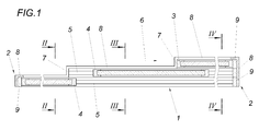
- the illustrated sliding window for a roof has a constructed of two longitudinal legs 1 and two transverse legs 2 floor frame for a total of three wings 3 and 4, of which two wings 4 are formed as sliding sash, while the uppermost wing 3 is fixed. Instead of the wing 3, a non-translucent cover of the floor frame could occur.
- the sliding sash 4 are in lateral displacement guides. 5 slidably mounted, which are associated with the longitudinal legs 1 of the floor frame.
- the length of the sliding guides 5 for the sliding sash 4 is limited to the displacement required for opening the sliding sashes 4 in one direction 6. Accordingly, the longitudinal legs 1 of the floor frame are stepped in the longitudinal direction in dependence on the different length of the sliding guides 5. In the closed position of the sliding sash 4, the sliding guides 5 end with the sliding sashes 4.
- the floor frame has a gradation with end faces 7 of the sliding guides 5 due to the sliding guides 5.
- a suitable thermal insulation of the floor frame comprises an effective external thermal separation, which is indicated schematically in the drawing and designated 8.
- This thermal separation 8 which may be designed differently, because it is only necessary to avoid cold bridges between the floor frame, the window outside and the floor frame receiving building opening, ensures that the floor frame is in terms of building physics in the warm area of the window.
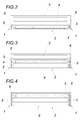
- the sliding guides 5 forming profile are constructed, as shown in particular from Fig. 2 to 4 evident.
- the later shift guides 5 forming profile only needs to be cut to length according to the respective required displacement paths for the individual sliding sash 4 to connect the cut longitudinal sections of the profile superimposed to the longitudinal legs 1, which then together with the transverse legs 2 the Floor frame revealed.
- the Transverse leg 2 similar to the longitudinal legs 1 composed of individual longitudinal sections 9 of a profile which is not mandatory
- the entire floor frame can be constructed of individual profile sections modular according to the respective design requirements.
- the longitudinal sections 9 of the profile for the transverse legs may, but need not, correspond to the profile for the sliding guides 5.
- the thermal separation 8 is of course also provided in the region of the transverse leg 2.
Landscapes
- Engineering & Computer Science (AREA)
- Architecture (AREA)
- Civil Engineering (AREA)
- Structural Engineering (AREA)
- Physics & Mathematics (AREA)
- Electromagnetism (AREA)
- Door And Window Frames Mounted To Openings (AREA)
- Wing Frames And Configurations (AREA)
Abstract
Description
- Die Erfindung bezieht sich auf ein Schiebefenster, insbesondere für ein Dach, mit einem über eine thermische Trennung in einer Bauöffnung gehaltenen Stockrahmen für wenigstens zwei Schiebeflügel, die in zumindest um die Flügeldicke senkrecht zur Flügelebene gegeneinander versetzten Verschiebeführungen gelagert sind und einander in der Offenstellung überdecken.
- Bei mehrflügeligen Schiebefenstern für Dächer ist es bekannt (
DE 101 13 535 A1 ,DE 10 2005 050 022 A1 ), die Schiebeflügel in einem Stockrahmen zu lagern, der im Bereich seiner einander gegenüberliegenden Längsschenkel Verschiebeführungen für die einzelnen Schiebeflügel aufweist, sodass die Schiebeflügel aus ihrer Schließstellung in eine Offenstellung verschoben werden können, in der die einzelnen Schiebeflügel übereinander zu liegen kommen. Nachteilig bei diesen bekannten Schiebefenstern ist vor allem, dass aufgrund der über die Länge der Rahmenschenkel verlaufenden Verschiebeführungen Kältebrücken gebildet werden, insbesondere wenn diese Verschiebeführungen aus einem metallischen Werkstoff bestehen, dessen Einsatz sich bei höheren Belastungen, beispielsweise aufgrund größerer Fensterflächen, kaum vermeiden lässt. Mit Ausnahme der jeweils untersten Verschiebeführung ragen die darüberliegenden Verschiebeführungen in der Schließstellung der Schiebeflügel ja in axialer Richtung über die Schiebeflügel nach außen vor, sodass über die Verschiebeführungen als Wärmeleiter ein Wärmeaustausch zwischen der Innenseite und der Außenseite des Schiebefensters stattfinden kann, selbst wenn der Stockrahmen über eine thermische Trennung in der jeweiligen Bauöffnung gehalten wird, sodass der Stockrahmen gegenüber den ihn aufnehmenden, kalten Bauteilen wärmegedämmt ist. - Der Erfindung liegt somit die Aufgabe zugrunde, ein Schiebefenster der eingangs geschilderten Art so auszugestalten, dass bei geschlossenen Schiebeflügeln eine gute Wärmedämmung sichergestellt werden kann.
- Die Erfindung löst die gestellte Aufgabe dadurch, dass die Verschiebeführungen entsprechend den unterschiedlichen Verschiebewegen der einzelnen Schiebeflügel unterschiedlich lang ausgebildet sind.
- Aufgrund der Beschränkung der Länge der Verschiebeführungen für den jeweils zum Öffnen nach einer Seite benötigten Verschiebeweg der Schiebeflügel wird in der Schließstellung der Schiebeflügel vermieden, dass die Verschiebeführungen über den geschlossenen Schiebeflügel hinaus nach außen vorstehen, sodass mit einer entsprechenden thermischen Trennung des Stockrahmens gegenüber der ihn aufnehmenden Bauöffnung Kältebrücken durch die Verschiebeführungen ausgeschlossen werden können. Schiebefenster der erfindungsgemäßen Art können daher die durch die Schiebeflügel gegebenen, vorteilhaften Wärmedämmeigenschaften tatsächlich nützen, weil eben die sonst durch die Verschiebeführungen für die Schiebeflügel bedingten Kältebrücken vermieden werden, und zwar unabhängig davon, ob die Schiebeflügel horizontal oder in Richtung der Falllinie verschoben werden sollen. Aus diesem Grunde ist die Erfindung auch nicht auf Schiebefenster für Dächer eingeschränkt, obwohl Dachfenster ein bevorzugtes Anwendungsgebiet für die Erfindung darstellen.
- Grundsätzlich ist es möglich, die Verschiebeführungen in einem Stockrahmen mit einheitlicher Höhe der Rahmenschenkel vorzusehen. Einfachere Konstruktionsbedingungen ergeben sich allerdings, wenn der Stockrahmen eine der Länge der Verschiebeführungen entsprechende Abstufung in Verschieberichtung der Schiebeflügel aufweist. Dies gilt insbesondere für eine Modulbauweise, bei der der Stockrahmen aus je eine Verschiebeführung bildenden Längsabschnitten eines Profils zusammengesetzt ist, sodass für die in Verschieberichtung der Schiebeflügel verlaufenden Längsschenkel des Stockrahmens eine vorteilhafte Anpassung an die jeweiligen Konstruktionsanforderungen erreicht werden kann, weil lediglich die Längsschenkel des Stockrahmens entsprechend der jeweiligen Anzahl der Schiebeflügel und der Flügelabmessungen in Verschieberichtung aus den die Verschiebeführung bildenden, gemäß den konstruktiven Vorgaben abgelängten Längsabschnitten des Profils zusammengesetzt werden müssen. Die diese Längsschenkel verbindenden Querschenkel des Stockrahmens können ebenfalls aus einzelnen der Profilhöhe der Verschiebeführungen entsprechenden Längsabschnitten eines Profils aufgebaut werden, was aber nicht zwingend ist. Der in dieser Weise zusammengesetzte Stockrahmen ist lediglich über eine thermische Trennung in die Bauöffnung einzusetzen, wobei darauf zu achten ist, dass auch die sich durch die Abstufung des Stockrahmens ergebenden stirnseitigen Enden der Verschiebeführungen von der thermischen Trennung umfasst werden. Die thermische Trennung kann dabei unterschiedlich ausfallen und beispielsweise durch eine Wärmedämmung aus Schaumstoff gebildet werden. Es kommt ja nicht auf die Art der Ausbildung der Wärmedämmung an, sondern darauf, dass sich eine thermische Trennung gegenüber der Außenseite des Fenster bzw. gegenüber der Bauöffnung ergibt.
- In der Zeichnung ist der Erfindungsgegenstand beispielsweise dargestellt. Es zeigen
- Fig. 1
- ein erfindungsgemäßes Schiebefenster für ein Dach in einem schematischen Längsschnitt und die
- Fig. 2
- bis 4 je einen Schnitt nach den Linien II-II bis IV-IV der
Fig.1 . - Das dargestellte Schiebefenster für ein Dach weist einen aus zwei Längsschenkeln 1 und zwei Querschenkeln 2 aufgebauten Stockrahmen für insgesamt drei Flügel 3 und 4 auf, von denen zwei Flügel 4 als Schiebeflügel ausgebildet sind, während der oberste Flügel 3 feststehend angeordnet ist. Anstelle des Flügels 3 könnte auch eine nicht lichtdurchlässige Abdeckung des Stockrahmens treten. Die Schiebeflügel 4 sind in seitlichen Verschiebeführungen 5 verschiebbar gelagert, die den Längsschenkeln 1 des Stockrahmens zugeordnet sind. Zum Unterschied von herkömmlichen Schiebefenstern dieser Art ist die Länge der Verschiebeführungen 5 für die Schiebeflügel 4 auf den Verschiebeweg beschränkt, der für das Öffnen der Schiebeflügel 4 in einer Richtung 6 erforderlich ist. Dementsprechend sind die Längsschenkel 1 des Stockrahmens in Längsrichtung in Abhängigkeit von der unterschiedlichen Länge der Verschiebeführungen 5 abgestuft. In der Schließstellung der Schiebeflügel 4 enden die Verschiebeführungen 5 mit den Schiebeflügeln 4.
- Der Stockrahmen weist aufgrund der Verschiebeführungen 5 eine Abstufung mit Stirnseiten 7 der Verschiebeführungen 5 auf. Mit Hilfe einer geeigneten Wärmedämmung umfasst der Stockrahmen eine nach außen wirksame thermische Trennung auf, die in der Zeichnung schematisch angedeutet und mit 8 bezeichnet ist. Diese thermische Trennung 8, die unterschiedlich ausgeführt sein kann, weil es ja lediglich darum geht, Kältebrücken zwischen dem Stockrahmen, der Fensteraußenseite und der den Stockrahmen aufnehmenden Bauöffnung zu vermeiden, stellt sicher, dass sich der Stockrahmen bauphysikalisch im warmen Bereich des Fensters befindet. Bei geschlossenen Schiebeflügeln 4 ragt kein Teil der Verschiebeführungen 5 über die thermische Trennung 8 auf die Außenseite des Schiebefensters vor, was eine wesentliche Voraussetzung für die Vermeidung von Kältebrücken durch die Verschiebeführungen 5 darstellt, die ja bei größeren aufzunehmenden Lasten im Allgemeinen aus einem metallischen Werkstoff, vorzugsweise Aluminium, bestehen werden.
- Besonders einfache Konstruktionsverhältnisse ergeben sich, wenn die Längsschenkel 1 des Stockrahmens aus einem in unterschiedlichen Längen abgelängten, die Verschiebeführungen 5 bildenden Profil aufgebaut werden, wie dies insbesondere aus den
Fig. 2 bis 4 hervorgeht. In diesem Fall braucht ja das die späteren Verschiebeführungen 5 bildende Profil lediglich entsprechend den jeweils geforderten Verschiebewegen für die einzelnen Schiebeflügel 4 abgelängt zu werden, um die abgelängten Längsabschnitte des Profils miteinander übereinanderliegend zu den Längsschenkeln 1 zu verbinden, die dann zusammen mit den Querschenkeln 2 den Stockrahmen ergeben. Werden die Querschenkel 2 ähnlich den Längsschenkeln 1 aus einzelnen Längsabschnitten 9 eines Profils zusammengesetzt, was nicht zwingend ist, so kann der gesamte Stockrahmen aus einzelnen Profilabschnitten modulartig gemäß den jeweiligen konstruktiven Anforderungen aufgebaut werden. Die Längsabschnitte 9 des Profils für die Querschenkel können, müssen jedoch nicht, dem Profil für die Verschiebeführungen 5 entsprechen. Die thermische Trennung 8 ist selbstverständlich auch im Bereich der Querschenkel 2 vorzusehen. - Wie sich insbesondere aus der
Fig. 4 ergibt, ist aus Gründen der Konstruktionsvereinfachung auch der feststehende Flügel 3 in einem Längsabschnitt des Profils für die Verschiebeführungen 5 gehalten, obwohl die Verschiebbarkeit dieses Flügels 3 nicht gegeben ist.
Claims (3)
- Schiebefenster, insbesondere für ein Dach, mit einem über eine thermische Trennung (8) in einer Bauöffnung gehaltenen Stockrahmen für wenigstens zwei Schiebeflügel (4), die in zumindest um die Flügeldicke senkrecht zur Flügelebene gegeneinander versetzten Verschiebeführungen (5) gelagert sind und einander in der Offenstellung überdecken, dadurch gekennzeichnet, dass die Verschiebeführungen (4) entsprechend den unterschiedlichen Verschiebewegen der einzelnen Schiebeflügel unterschiedlich lang ausgebildet sind.
- Schiebefenster nach Anspruch 1, dadurch gekennzeichnet, dass der Stockrahmen eine der Länge der Verschiebeführungen entsprechende Abstufung in Verschieberichtung (6) der Schiebeflügel (4) aufweist.
- Schiebefenster nach Anspruch 2, dadurch gekennzeichnet, dass der Stockrahmen aus je eine Verschiebeführung (5) bildenden Längsabschnitten eines Profils zusammengesetzt ist.
Applications Claiming Priority (1)
| Application Number | Priority Date | Filing Date | Title |
|---|---|---|---|
| ATA889/2011A AT511473B1 (de) | 2011-06-17 | 2011-06-17 | Schiebefenster, insbesondere für ein dach |
Publications (3)
| Publication Number | Publication Date |
|---|---|
| EP2535476A2 true EP2535476A2 (de) | 2012-12-19 |
| EP2535476A3 EP2535476A3 (de) | 2015-11-25 |
| EP2535476B1 EP2535476B1 (de) | 2018-07-18 |
Family
ID=46146683
Family Applications (1)
| Application Number | Title | Priority Date | Filing Date |
|---|---|---|---|
| EP12168047.4A Active EP2535476B1 (de) | 2011-06-17 | 2012-05-15 | Schiebefenster, insbesondere für ein dach |
Country Status (2)
| Country | Link |
|---|---|
| EP (1) | EP2535476B1 (de) |
| AT (1) | AT511473B1 (de) |
Citations (2)
| Publication number | Priority date | Publication date | Assignee | Title |
|---|---|---|---|---|
| DE10113535A1 (de) | 2001-03-20 | 2002-09-26 | Helmut Jechnerer | Fenster für Gebäude |
| DE102005050022A1 (de) | 2005-07-07 | 2007-01-11 | Citak, Fatma | Motorgetriebens Schiebefenster |
Family Cites Families (5)
| Publication number | Priority date | Publication date | Assignee | Title |
|---|---|---|---|---|
| GB447654A (en) * | 1934-09-28 | 1936-05-22 | Johaenn Trager | Improvements in telescopically sliding roofs |
| FR2473596A1 (fr) * | 1980-01-09 | 1981-07-17 | Garcia Tortosa Francisco | Toiture pliable perfectionnee |
| DE3101944C2 (de) * | 1981-01-22 | 1983-01-05 | Losch GmbH u. Co Überdachungssysteme, 7024 Filderstadt | Schiebedach für Gebäude |
| DE3541835A1 (de) * | 1985-11-27 | 1987-06-04 | Horst Schrumpf | Vorrichtung zur ueberdachung von terrassen, insbesondere von dachterrassen |
| US6141907A (en) * | 1998-05-12 | 2000-11-07 | Parazader; Stephen | Biparting panel assembly |
-
2011
- 2011-06-17 AT ATA889/2011A patent/AT511473B1/de not_active IP Right Cessation
-
2012
- 2012-05-15 EP EP12168047.4A patent/EP2535476B1/de active Active
Patent Citations (2)
| Publication number | Priority date | Publication date | Assignee | Title |
|---|---|---|---|---|
| DE10113535A1 (de) | 2001-03-20 | 2002-09-26 | Helmut Jechnerer | Fenster für Gebäude |
| DE102005050022A1 (de) | 2005-07-07 | 2007-01-11 | Citak, Fatma | Motorgetriebens Schiebefenster |
Also Published As
| Publication number | Publication date |
|---|---|
| EP2535476B1 (de) | 2018-07-18 |
| EP2535476A3 (de) | 2015-11-25 |
| AT511473A4 (de) | 2012-12-15 |
| AT511473B1 (de) | 2012-12-15 |
Similar Documents
| Publication | Publication Date | Title |
|---|---|---|
| EP0802300A2 (de) | Rahmenwerk aus Metallprofilen in Brandschutzausführung für Fenster, Türen, Fassaden oder Glasdächer | |
| DE102010012159A1 (de) | Mehrteiliges Profilrahmensystem für Türen, Tore, Wintergärten und Fenster | |
| DE102016125602B4 (de) | Isolierkörper für mehrschalige Bauelemente | |
| EP2666948B1 (de) | Rahmenanordnung für ein Sektionaltorpaneel | |
| DE202014010902U1 (de) | Isolierelement für Fassaden- oder Lichtdachkonstruktionen | |
| EP3184723B1 (de) | Verbundprofil für fenster, türen oder dergleichen | |
| EP2472044B2 (de) | Flügel- und/oder Blendrahmen eines Fensters, einer Tür oder dergleichen | |
| DE202007000004U1 (de) | Fensterprofil | |
| EP2573307A1 (de) | Mehrteiliges Profilrahmensytem für Türen, Tore, Wintergärten und Fenster | |
| AT406700B (de) | Tür, insbesondere brandschutztür | |
| EP2947217B1 (de) | Dämmblock für ein fenster oder dergleichen | |
| EP2535476B1 (de) | Schiebefenster, insbesondere für ein dach | |
| EP2369115A2 (de) | Aushebesicherung für Schiebefenster oder Schiebetüren | |
| DE202010013228U1 (de) | Auflageanordnung für ein Fenster, eine Tür o.dgl. | |
| DE102015107324A1 (de) | Profilschienensystem für den Einbau von Schiebetüren in Hohlwände | |
| AT500368A1 (de) | Schwellenprofil für eine schiebetür oder ein schiebefenster | |
| EP2876240B1 (de) | Fenster oder Tür | |
| DE102017118275B4 (de) | Torvorrichtung und diese enthaltende Toranordnung | |
| DE202013006232U1 (de) | Tor mit Sandwichplatte | |
| DE102015201675A1 (de) | Tür- oder Fenstersystem | |
| DE3134742A1 (de) | "fenster- oder tuerfluegel" | |
| DE202018106456U1 (de) | Schnäpperprofil | |
| EP2453096B1 (de) | Schieberahmenvorrichtung | |
| DE10300240A1 (de) | Glaswand | |
| EP2584129B1 (de) | Schiebefenster oder schiebetür |
Legal Events
| Date | Code | Title | Description |
|---|---|---|---|
| PUAI | Public reference made under article 153(3) epc to a published international application that has entered the european phase |
Free format text: ORIGINAL CODE: 0009012 |
|
| AK | Designated contracting states |
Kind code of ref document: A2 Designated state(s): AL AT BE BG CH CY CZ DE DK EE ES FI FR GB GR HR HU IE IS IT LI LT LU LV MC MK MT NL NO PL PT RO RS SE SI SK SM TR |
|
| AX | Request for extension of the european patent |
Extension state: BA ME |
|
| PUAL | Search report despatched |
Free format text: ORIGINAL CODE: 0009013 |
|
| AK | Designated contracting states |
Kind code of ref document: A3 Designated state(s): AL AT BE BG CH CY CZ DE DK EE ES FI FR GB GR HR HU IE IS IT LI LT LU LV MC MK MT NL NO PL PT RO RS SE SI SK SM TR |
|
| AX | Request for extension of the european patent |
Extension state: BA ME |
|
| RIC1 | Information provided on ipc code assigned before grant |
Ipc: E04B 7/16 20060101ALI20151021BHEP Ipc: E04D 13/035 20060101AFI20151021BHEP |
|
| 17P | Request for examination filed |
Effective date: 20160523 |
|
| RBV | Designated contracting states (corrected) |
Designated state(s): AL AT BE BG CH CY CZ DE DK EE ES FI FR GB GR HR HU IE IS IT LI LT LU LV MC MK MT NL NO PL PT RO RS SE SI SK SM TR |
|
| GRAP | Despatch of communication of intention to grant a patent |
Free format text: ORIGINAL CODE: EPIDOSNIGR1 |
|
| STAA | Information on the status of an ep patent application or granted ep patent |
Free format text: STATUS: GRANT OF PATENT IS INTENDED |
|
| INTG | Intention to grant announced |
Effective date: 20180320 |
|
| GRAS | Grant fee paid |
Free format text: ORIGINAL CODE: EPIDOSNIGR3 |
|
| GRAA | (expected) grant |
Free format text: ORIGINAL CODE: 0009210 |
|
| STAA | Information on the status of an ep patent application or granted ep patent |
Free format text: STATUS: THE PATENT HAS BEEN GRANTED |
|
| AK | Designated contracting states |
Kind code of ref document: B1 Designated state(s): AL AT BE BG CH CY CZ DE DK EE ES FI FR GB GR HR HU IE IS IT LI LT LU LV MC MK MT NL NO PL PT RO RS SE SI SK SM TR |
|
| REG | Reference to a national code |
Ref country code: GB Ref legal event code: FG4D Free format text: NOT ENGLISH |
|
| REG | Reference to a national code |
Ref country code: CH Ref legal event code: EP |
|
| REG | Reference to a national code |
Ref country code: IE Ref legal event code: FG4D Free format text: LANGUAGE OF EP DOCUMENT: GERMAN |
|
| REG | Reference to a national code |
Ref country code: AT Ref legal event code: REF Ref document number: 1019525 Country of ref document: AT Kind code of ref document: T Effective date: 20180815 |
|
| REG | Reference to a national code |
Ref country code: DE Ref legal event code: R096 Ref document number: 502012013044 Country of ref document: DE |
|
| REG | Reference to a national code |
Ref country code: NL Ref legal event code: MP Effective date: 20180718 |
|
| REG | Reference to a national code |
Ref country code: LT Ref legal event code: MG4D |
|
| PG25 | Lapsed in a contracting state [announced via postgrant information from national office to epo] |
Ref country code: NL Free format text: LAPSE BECAUSE OF FAILURE TO SUBMIT A TRANSLATION OF THE DESCRIPTION OR TO PAY THE FEE WITHIN THE PRESCRIBED TIME-LIMIT Effective date: 20180718 |
|
| PG25 | Lapsed in a contracting state [announced via postgrant information from national office to epo] |
Ref country code: SE Free format text: LAPSE BECAUSE OF FAILURE TO SUBMIT A TRANSLATION OF THE DESCRIPTION OR TO PAY THE FEE WITHIN THE PRESCRIBED TIME-LIMIT Effective date: 20180718 Ref country code: IS Free format text: LAPSE BECAUSE OF FAILURE TO SUBMIT A TRANSLATION OF THE DESCRIPTION OR TO PAY THE FEE WITHIN THE PRESCRIBED TIME-LIMIT Effective date: 20181118 Ref country code: BG Free format text: LAPSE BECAUSE OF FAILURE TO SUBMIT A TRANSLATION OF THE DESCRIPTION OR TO PAY THE FEE WITHIN THE PRESCRIBED TIME-LIMIT Effective date: 20181018 Ref country code: GR Free format text: LAPSE BECAUSE OF FAILURE TO SUBMIT A TRANSLATION OF THE DESCRIPTION OR TO PAY THE FEE WITHIN THE PRESCRIBED TIME-LIMIT Effective date: 20181019 Ref country code: NO Free format text: LAPSE BECAUSE OF FAILURE TO SUBMIT A TRANSLATION OF THE DESCRIPTION OR TO PAY THE FEE WITHIN THE PRESCRIBED TIME-LIMIT Effective date: 20181018 Ref country code: LT Free format text: LAPSE BECAUSE OF FAILURE TO SUBMIT A TRANSLATION OF THE DESCRIPTION OR TO PAY THE FEE WITHIN THE PRESCRIBED TIME-LIMIT Effective date: 20180718 Ref country code: RS Free format text: LAPSE BECAUSE OF FAILURE TO SUBMIT A TRANSLATION OF THE DESCRIPTION OR TO PAY THE FEE WITHIN THE PRESCRIBED TIME-LIMIT Effective date: 20180718 Ref country code: FI Free format text: LAPSE BECAUSE OF FAILURE TO SUBMIT A TRANSLATION OF THE DESCRIPTION OR TO PAY THE FEE WITHIN THE PRESCRIBED TIME-LIMIT Effective date: 20180718 Ref country code: PL Free format text: LAPSE BECAUSE OF FAILURE TO SUBMIT A TRANSLATION OF THE DESCRIPTION OR TO PAY THE FEE WITHIN THE PRESCRIBED TIME-LIMIT Effective date: 20180718 |
|
| PG25 | Lapsed in a contracting state [announced via postgrant information from national office to epo] |
Ref country code: LV Free format text: LAPSE BECAUSE OF FAILURE TO SUBMIT A TRANSLATION OF THE DESCRIPTION OR TO PAY THE FEE WITHIN THE PRESCRIBED TIME-LIMIT Effective date: 20180718 Ref country code: AL Free format text: LAPSE BECAUSE OF FAILURE TO SUBMIT A TRANSLATION OF THE DESCRIPTION OR TO PAY THE FEE WITHIN THE PRESCRIBED TIME-LIMIT Effective date: 20180718 Ref country code: HR Free format text: LAPSE BECAUSE OF FAILURE TO SUBMIT A TRANSLATION OF THE DESCRIPTION OR TO PAY THE FEE WITHIN THE PRESCRIBED TIME-LIMIT Effective date: 20180718 |
|
| REG | Reference to a national code |
Ref country code: CH Ref legal event code: NV Representative=s name: E. BLUM AND CO. AG PATENT- UND MARKENANWAELTE , CH |
|
| REG | Reference to a national code |
Ref country code: DE Ref legal event code: R097 Ref document number: 502012013044 Country of ref document: DE |
|
| PG25 | Lapsed in a contracting state [announced via postgrant information from national office to epo] |
Ref country code: IT Free format text: LAPSE BECAUSE OF FAILURE TO SUBMIT A TRANSLATION OF THE DESCRIPTION OR TO PAY THE FEE WITHIN THE PRESCRIBED TIME-LIMIT Effective date: 20180718 Ref country code: ES Free format text: LAPSE BECAUSE OF FAILURE TO SUBMIT A TRANSLATION OF THE DESCRIPTION OR TO PAY THE FEE WITHIN THE PRESCRIBED TIME-LIMIT Effective date: 20180718 Ref country code: CZ Free format text: LAPSE BECAUSE OF FAILURE TO SUBMIT A TRANSLATION OF THE DESCRIPTION OR TO PAY THE FEE WITHIN THE PRESCRIBED TIME-LIMIT Effective date: 20180718 Ref country code: EE Free format text: LAPSE BECAUSE OF FAILURE TO SUBMIT A TRANSLATION OF THE DESCRIPTION OR TO PAY THE FEE WITHIN THE PRESCRIBED TIME-LIMIT Effective date: 20180718 Ref country code: RO Free format text: LAPSE BECAUSE OF FAILURE TO SUBMIT A TRANSLATION OF THE DESCRIPTION OR TO PAY THE FEE WITHIN THE PRESCRIBED TIME-LIMIT Effective date: 20180718 |
|
| PLBE | No opposition filed within time limit |
Free format text: ORIGINAL CODE: 0009261 |
|
| STAA | Information on the status of an ep patent application or granted ep patent |
Free format text: STATUS: NO OPPOSITION FILED WITHIN TIME LIMIT |
|
| PG25 | Lapsed in a contracting state [announced via postgrant information from national office to epo] |
Ref country code: SM Free format text: LAPSE BECAUSE OF FAILURE TO SUBMIT A TRANSLATION OF THE DESCRIPTION OR TO PAY THE FEE WITHIN THE PRESCRIBED TIME-LIMIT Effective date: 20180718 Ref country code: DK Free format text: LAPSE BECAUSE OF FAILURE TO SUBMIT A TRANSLATION OF THE DESCRIPTION OR TO PAY THE FEE WITHIN THE PRESCRIBED TIME-LIMIT Effective date: 20180718 Ref country code: SK Free format text: LAPSE BECAUSE OF FAILURE TO SUBMIT A TRANSLATION OF THE DESCRIPTION OR TO PAY THE FEE WITHIN THE PRESCRIBED TIME-LIMIT Effective date: 20180718 |
|
| 26N | No opposition filed |
Effective date: 20190423 |
|
| PG25 | Lapsed in a contracting state [announced via postgrant information from national office to epo] |
Ref country code: SI Free format text: LAPSE BECAUSE OF FAILURE TO SUBMIT A TRANSLATION OF THE DESCRIPTION OR TO PAY THE FEE WITHIN THE PRESCRIBED TIME-LIMIT Effective date: 20180718 |
|
| GBPC | Gb: european patent ceased through non-payment of renewal fee |
Effective date: 20190515 |
|
| PG25 | Lapsed in a contracting state [announced via postgrant information from national office to epo] |
Ref country code: MC Free format text: LAPSE BECAUSE OF FAILURE TO SUBMIT A TRANSLATION OF THE DESCRIPTION OR TO PAY THE FEE WITHIN THE PRESCRIBED TIME-LIMIT Effective date: 20180718 |
|
| REG | Reference to a national code |
Ref country code: BE Ref legal event code: MM Effective date: 20190531 |
|
| PG25 | Lapsed in a contracting state [announced via postgrant information from national office to epo] |
Ref country code: LU Free format text: LAPSE BECAUSE OF NON-PAYMENT OF DUE FEES Effective date: 20190515 |
|
| PG25 | Lapsed in a contracting state [announced via postgrant information from national office to epo] |
Ref country code: TR Free format text: LAPSE BECAUSE OF FAILURE TO SUBMIT A TRANSLATION OF THE DESCRIPTION OR TO PAY THE FEE WITHIN THE PRESCRIBED TIME-LIMIT Effective date: 20180718 |
|
| PG25 | Lapsed in a contracting state [announced via postgrant information from national office to epo] |
Ref country code: IE Free format text: LAPSE BECAUSE OF NON-PAYMENT OF DUE FEES Effective date: 20190515 Ref country code: GB Free format text: LAPSE BECAUSE OF NON-PAYMENT OF DUE FEES Effective date: 20190515 |
|
| PG25 | Lapsed in a contracting state [announced via postgrant information from national office to epo] |
Ref country code: BE Free format text: LAPSE BECAUSE OF NON-PAYMENT OF DUE FEES Effective date: 20190531 |
|
| PG25 | Lapsed in a contracting state [announced via postgrant information from national office to epo] |
Ref country code: FR Free format text: LAPSE BECAUSE OF NON-PAYMENT OF DUE FEES Effective date: 20190531 Ref country code: PT Free format text: LAPSE BECAUSE OF FAILURE TO SUBMIT A TRANSLATION OF THE DESCRIPTION OR TO PAY THE FEE WITHIN THE PRESCRIBED TIME-LIMIT Effective date: 20181118 |
|
| PG25 | Lapsed in a contracting state [announced via postgrant information from national office to epo] |
Ref country code: CY Free format text: LAPSE BECAUSE OF FAILURE TO SUBMIT A TRANSLATION OF THE DESCRIPTION OR TO PAY THE FEE WITHIN THE PRESCRIBED TIME-LIMIT Effective date: 20180718 |
|
| PG25 | Lapsed in a contracting state [announced via postgrant information from national office to epo] |
Ref country code: MT Free format text: LAPSE BECAUSE OF FAILURE TO SUBMIT A TRANSLATION OF THE DESCRIPTION OR TO PAY THE FEE WITHIN THE PRESCRIBED TIME-LIMIT Effective date: 20180718 Ref country code: HU Free format text: LAPSE BECAUSE OF FAILURE TO SUBMIT A TRANSLATION OF THE DESCRIPTION OR TO PAY THE FEE WITHIN THE PRESCRIBED TIME-LIMIT; INVALID AB INITIO Effective date: 20120515 |
|
| PG25 | Lapsed in a contracting state [announced via postgrant information from national office to epo] |
Ref country code: MK Free format text: LAPSE BECAUSE OF FAILURE TO SUBMIT A TRANSLATION OF THE DESCRIPTION OR TO PAY THE FEE WITHIN THE PRESCRIBED TIME-LIMIT Effective date: 20180718 |
|
| PGFP | Annual fee paid to national office [announced via postgrant information from national office to epo] |
Ref country code: DE Payment date: 20250507 Year of fee payment: 14 |
|
| PGFP | Annual fee paid to national office [announced via postgrant information from national office to epo] |
Ref country code: CH Payment date: 20250601 Year of fee payment: 14 |
|
| PGFP | Annual fee paid to national office [announced via postgrant information from national office to epo] |
Ref country code: AT Payment date: 20250508 Year of fee payment: 14 |