EP2535517A2 - Dispositif de rotor pour un turboréacteur avec un disque et plusieurs aubes mobiles - Google Patents
Dispositif de rotor pour un turboréacteur avec un disque et plusieurs aubes mobiles Download PDFInfo
- Publication number
- EP2535517A2 EP2535517A2 EP12004445A EP12004445A EP2535517A2 EP 2535517 A2 EP2535517 A2 EP 2535517A2 EP 12004445 A EP12004445 A EP 12004445A EP 12004445 A EP12004445 A EP 12004445A EP 2535517 A2 EP2535517 A2 EP 2535517A2
- Authority
- EP
- European Patent Office
- Prior art keywords
- blade
- securing
- securing segment
- blades
- edge
- Prior art date
- Legal status (The legal status is an assumption and is not a legal conclusion. Google has not performed a legal analysis and makes no representation as to the accuracy of the status listed.)
- Withdrawn
Links
- 238000007789 sealing Methods 0.000 claims description 10
- 238000013016 damping Methods 0.000 claims description 5
- 230000007704 transition Effects 0.000 claims description 5
- 125000006850 spacer group Chemical group 0.000 claims description 3
- 230000002940 repellent Effects 0.000 claims description 2
- 239000005871 repellent Substances 0.000 claims description 2
- 230000037431 insertion Effects 0.000 claims 1
- 238000003780 insertion Methods 0.000 claims 1
- 238000005452 bending Methods 0.000 description 6
- 238000004519 manufacturing process Methods 0.000 description 6
- 230000000694 effects Effects 0.000 description 3
- 239000000463 material Substances 0.000 description 3
- 239000013585 weight reducing agent Substances 0.000 description 2
- 230000000712 assembly Effects 0.000 description 1
- 238000000429 assembly Methods 0.000 description 1
- 230000005540 biological transmission Effects 0.000 description 1
- 238000010276 construction Methods 0.000 description 1
- 238000006073 displacement reaction Methods 0.000 description 1
- 230000002349 favourable effect Effects 0.000 description 1
- 239000012530 fluid Substances 0.000 description 1
- 238000009434 installation Methods 0.000 description 1
- 230000003993 interaction Effects 0.000 description 1
- 230000002093 peripheral effect Effects 0.000 description 1
- 238000006798 ring closing metathesis reaction Methods 0.000 description 1
Images


Classifications
-
- F—MECHANICAL ENGINEERING; LIGHTING; HEATING; WEAPONS; BLASTING
- F01—MACHINES OR ENGINES IN GENERAL; ENGINE PLANTS IN GENERAL; STEAM ENGINES
- F01D—NON-POSITIVE DISPLACEMENT MACHINES OR ENGINES, e.g. STEAM TURBINES
- F01D5/00—Blades; Blade-carrying members; Heating, heat-insulating, cooling or antivibration means on the blades or the members
- F01D5/30—Fixing blades to rotors; Blade roots ; Blade spacers
- F01D5/3007—Fixing blades to rotors; Blade roots ; Blade spacers of axial insertion type
- F01D5/3015—Fixing blades to rotors; Blade roots ; Blade spacers of axial insertion type with side plates
-
- F—MECHANICAL ENGINEERING; LIGHTING; HEATING; WEAPONS; BLASTING
- F01—MACHINES OR ENGINES IN GENERAL; ENGINE PLANTS IN GENERAL; STEAM ENGINES
- F01D—NON-POSITIVE DISPLACEMENT MACHINES OR ENGINES, e.g. STEAM TURBINES
- F01D5/00—Blades; Blade-carrying members; Heating, heat-insulating, cooling or antivibration means on the blades or the members
- F01D5/30—Fixing blades to rotors; Blade roots ; Blade spacers
- F01D5/32—Locking, e.g. by final locking blades or keys
- F01D5/326—Locking of axial insertion type blades by other means
-
- F—MECHANICAL ENGINEERING; LIGHTING; HEATING; WEAPONS; BLASTING
- F05—INDEXING SCHEMES RELATING TO ENGINES OR PUMPS IN VARIOUS SUBCLASSES OF CLASSES F01-F04
- F05D—INDEXING SCHEME FOR ASPECTS RELATING TO NON-POSITIVE-DISPLACEMENT MACHINES OR ENGINES, GAS-TURBINES OR JET-PROPULSION PLANTS
- F05D2250/00—Geometry
- F05D2250/10—Two-dimensional
- F05D2250/11—Two-dimensional triangular
-
- F—MECHANICAL ENGINEERING; LIGHTING; HEATING; WEAPONS; BLASTING
- F05—INDEXING SCHEMES RELATING TO ENGINES OR PUMPS IN VARIOUS SUBCLASSES OF CLASSES F01-F04
- F05D—INDEXING SCHEME FOR ASPECTS RELATING TO NON-POSITIVE-DISPLACEMENT MACHINES OR ENGINES, GAS-TURBINES OR JET-PROPULSION PLANTS
- F05D2260/00—Function
- F05D2260/30—Retaining components in desired mutual position
- F05D2260/36—Retaining components in desired mutual position by a form fit connection, e.g. by interlocking
-
- Y—GENERAL TAGGING OF NEW TECHNOLOGICAL DEVELOPMENTS; GENERAL TAGGING OF CROSS-SECTIONAL TECHNOLOGIES SPANNING OVER SEVERAL SECTIONS OF THE IPC; TECHNICAL SUBJECTS COVERED BY FORMER USPC CROSS-REFERENCE ART COLLECTIONS [XRACs] AND DIGESTS
- Y02—TECHNOLOGIES OR APPLICATIONS FOR MITIGATION OR ADAPTATION AGAINST CLIMATE CHANGE
- Y02T—CLIMATE CHANGE MITIGATION TECHNOLOGIES RELATED TO TRANSPORTATION
- Y02T50/00—Aeronautics or air transport
- Y02T50/60—Efficient propulsion technologies, e.g. for aircraft
Definitions
- the invention relates to a rotor device for a jet engine with a disc wheel and a plurality of blades connected to the disc wheel according to the closer defined in the preamble of claim 1.
- jet engines with turbine designs are known in which blades are arranged in each case via so-called Fannenbaumfpune in receiving rails of the disk wheel, wherein the receiving rails extend in the axial direction in the disk wheel.
- the fuse segments are based on one or more blades under load under load.
- the securing segments are mounted in the radial direction at one end in joints arranged below the inner shroud of the rotor blades and at the other end in a joint provided in the disk wheel.
- the joints of the blades facing and engaging in the joints surfaces of the securing segments are formed concentrically to a center of the disc wheel.
- the securing segments facing surfaces of the joints of the blades are usually formed straight.
- the relative movement between the securing segments and the blades may result in the contact area between a blade and a securing segment with respect to a fir tree root of the blade being arranged eccentrically in the circumferential direction, resulting in an unfavorable load application position.
- additional bending stresses and moments act on the fir-tree root which are particularly great in blades with a large platform overhang and reduce to an undesirable extent a lifetime of the blades and the disk wheel.
- the present invention is therefore an object of the invention to provide a rotor device for a jet engine with a disc wheel and a plurality of blades connected to the disc rotor, which are secured on Sich ceremoniesssegmenle in the axial direction relative to the disc wheel, in which the securing segments in a simple manner against a rotation relative to the blades are secured and in each case a defined contact area between the fuse segments and the wheels over the entire operating range of the rotor device is present.
- rotor device for a jet engine with a disc wheel and a plurality of blades connected to the disc rotor blades are each arranged via a blade root in a substantially axial direction in recesses of the disc wheel, wherein for securing the axial blades of the blades in the recesses of the disc wheel more Sichorungssegmente are provided which cooperate on the one hand in defined contact areas with joints of the blades and on the other hand with at least one joint of the disc wheel.
- a positive locking preventing a relative movement between the rotor blades and the securing segments ie a contour facing the rotor blades the securing segments and a contour of the joint of the rotor blades facing the securing segments are designed to be coordinated with one another in order to prevent a rotation of the securing segments relative to the rotor blades.
- a rotation of the securing segments of the securing ring is ensured relative to the blades, in particular during operation of the rotor device without additional means for fixing the securing segments relative to the blades, so that an assembly of the fuse segments is easy and quick to perform and one defined investment area between the fuse segments and the blades over the entire operating range of the device is maintained.
- costs for the production of the securing segments can be lower with respect to the securing segments known from the prior art with a profiled contour, since a plurality of successive production steps are required to produce the profiled contour.
- the rotor device according to the invention can be used for engines of various designs and is used in particular at any stage of a turbine. Furthermore, the rotor device according to the invention can also be used, for example, in a compressor or a fan of an engine.
- a securing segment facing the region of the joint of the blade is formed with a particular tooth-shaped profile body.
- a relative movement between the blade and the securing segment is in an advantageous development prevents the invention with a triangular-shaped portion having profiled body, which forms for this purpose a stop area for a correlating with the triangular portion of the profile body triangular recess of the securing segment.
- the triangular portion of the profile body is formed in cross-section of cutting blade edges in an intersection wherein a first blade edge is inclined in the circumferential direction of the blade relative to a platform of the blade, and a second blade edge extending from the radially extending from a joint bottom furthest extending intersection of the blade edges in the direction of the bottom of the joint, and wherein the triangular recess of the securing segment is formed in cross-section of two intersecting cutting edge segments and the profile body to prevent rotation of the Lau
- the vane forms a stop for the securing segment relative to the securing segment in the region of the point of intersection and cooperates in this area at least approximately with a region of the securing segment which surrounds the intersection of the securing segment.
- the point of the first blade edge which is furthest apart in the radial direction from the joint bottom of the joint of a blade forms a defined contact point for an associated securing segment, the securing segment being supported in the area of this point against undesired rotation in the circumferential direction of the disk wheel relative to the blade on the profile body ,
- the first securing segment edge of the securing segment runs in regions parallel to the first blade edge of the profile body of the moving blade to form a contact region between the moving blade and the securing segment.
- a defined region is created in a simple manner, in which there is a contact between the securing segment and the moving blade, in particular in an operating state of the rotor device.
- the manufacturing costs and / or the weight of the blade can be reduced in the inventive solution become.
- a weight reduction is in particular possible because of the employment or inclination of the profile body of the joint and the creation of a defined contact area between the securing segment and the blade not load-bearing material of the blade can be removed.
- a center of the contact region of the first securing segment edge and the first blade edge is arranged at least approximately centrally of the blade root of the rotor blade in the circumferential direction of the rotor device.
- the blades and the securing segments can advantageously be easily formed and / or have a longer service life.
- the securing segments can be designed for weight reduction, for example with Aussparbohrungen. Lifespan gain is particularly high on blades with a large platform overhang, such as rotor blade assemblies with low blade counts, because these devices can avoid excessive bending stresses due to the large platform overhang.
- the securing segment may have a third securing segment edge in cross section, which adjoins the first securing segment edge with respect to the intersection of the first securing segment edge and the second securing segment edge repellent direction, wherein the third securing segment edge first blade edge, in particular by a thereto angular arrangement, spaced runs.
- the distance between the third fuse segment edge and the first Laufetzaufelkante is particularly low, so that the third securing segment edge in a transition region between two adjacent blades in the radial direction comes very close to the joint bottom of the joint of the blade and thereby a good sealing effect can be achieved.
- sealing and / or damping devices between adjacent blades can be dispensed with or the sealing and / or damping devices can be made particularly small and / or simple.
- the third securing segment edge extends in the circumferential direction of the rotor device beyond a transition region of adjacent blade, so that a sealing effect of the securing segments is further improved.
- the second securing segment edge of the securing segment extends in an advantageous embodiment of a rotor device according to the invention to the second blade edge of the blade spaced, in particular by an angular arrangement relative to the second blade edge, so that prevents contact of the profile body with the securing segment in the region of the second blade edge and the second securing segment edge becomes.
- securing segments can have a joint with a profile body and each cooperate with a triangular recess portion of a securing segment.
- the securing segments can be formed with a triangular-shaped recess area and cooperate with a single blade.
- a securing segment may have a plurality of triangular-shaped recesses comprising areas and extend over a plurality, in particular two or three blades and cooperate on the profile body with the moving blades.
- the securing segments in a structurally simple embodiment of the rotor device according to the invention in an area facing the joint of the disc wheel at least one extension, which between one for the introduction of Securing segment in the rotor device first position and a second position with inserted securing segment displaced, in particular bendable, wherein, a radial extent of the securing segment with the extension located in the second position is greater than with the extension located in the first position.
- a wire may be arranged in the radial direction between the securing segment and the joint of the disk wheel in the circumferential direction of the rotor device extending spacer element.
- securing segments can be provided on both sides of the rotor blades in an axial direction on both sides of the invention be arranged, which are each arranged in joints of the blades and in at least one joint of the disc wheel.
- At least one sealing and / or damping element is arranged in the region of a gap between inner shrouds of two adjacent blades.
- a jet engine 1 is shown in a longitudinal sectional view.
- the jet engine 1 is formed with a bypass duct 2 and an inlet region 3, with a fan 4 adjoining the inlet region 3 downstream in a manner known per se.
- the fluid flow in the jet engine 1 is divided into a secondary flow and a core flow, wherein the secondary flow through the bypass channel 2 and the core flow flows into an engine core 5, which in turn in a conventional manner with a compressor device 6, a burner 7 and a turbine device 8 is executed.
- the turbine device 8 has three rotor devices 9, 10, 11, which are designed in a substantially comparable construction, the rotor device 9 being described in more detail below as representative of the other rotor devices 10, 11.
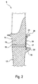
- the rotor device 9 which in the Fig. 2 can be seen in a sectional view, has a centrally disposed and connected to an engine axis 12 disc wheel 13, on which in the radially outer regions circumferentially a plurality of blades 14 are arranged.
- the rotor blades 14 each have a blade root, which is only shown schematically here and designed as a Tanncnbaumfuß 15, which is in each case arranged in one of the substantially axial direction in the disk wheel 13 and correlating with the Tannenbaumrü hit 15 recesses 16 of the disk wheel 13.
- a trained with multiple securing segments 17 flat locking ring 18 is provided, which in the area of Tannenbaumfpune 15 of the blades 14 on the one hand in a continuous disc wheel 13 arranged in the joint 19 and the other in below an inner shroud 20th or a platform of the running blades 14 arranged and extending in the circumferential direction of the disc wheel joints 21 of the blades 14 engages.
- a detail of the blade 14 with a running in the circumferential direction of the disc wheel 13 joint 21 is closer, the joint 21 has a below the substantially concentric with the engine axis 12 extending inner shroud 20 and integrally formed with the blade 14 profile body 22 has.
- maximum depth of the joint 21 of the blade 14 is formed by the underside of the inner shroud 20, the joint bottom 24.
- the tooth or sawtooth profile body 22 is disposed in the axial direction between the joint wall 23 of the joint 21 and the fir tree 15 and extends In the present case, the profile body 22 may extend over only a region of the width of the joint 21.
- the profile body 22 of the joint 21 forms a cross-section of presently three straight running blade edges 25, 26, 27 composing contour 35.
- a first blade edge 25 extends from an in the radial direction farthest from the joint base 24 remote point S1 with an angle relative to the inner shroud 20 of the blade 14, so that the first blade edge 25 in the present case in the same manner as an axially outer joint wall 23 of the joint 21 relative to the inner shroud 20 is inclined.
- the first blade edge 25 accordingly has an angle with respect to a tangent of the circumferential circle of the inner shroud 20, which runs through a center of the joint base 24 in the circumferential direction.
- the point S1 represents an intersection of the first blade edge 25 with a second blade edge 26, which together form a triangular region 37 of the profile body 22.
- the point of intersection S1 is located in an edge region of the joint 21 of the blade 14. Between the first blade edge 25 and the second blade edge 26, an angle of approximately 90 ° is provided.
- the profile body 22 is completed in cross section by a third blade edge 27 which extends between the first blade edge 25 and the bottom of the joint 24.
- All blades 14 are presently formed in each case with a joint 21 and a profile body 22 described above, wherein each profile body 22 cooperates in the installed position of the securing ring 1.8 with a securing segment 17 extending in Umtangscardi three blades 14.
- the securing segments 17 have a sawtooth profile 28 with three saw teeth 29, wherein between each one profile body 22 of the blades 14 and a saw tooth 29 of the securing segment 17 there is a positive locking preventing a relative movement between the moving blades 14 and the securing segment 17.
- Fig. 4 and Fig. 5 each show a fuse segment 17 and at least portions of blades 14 and the disc wheel 13 in a simplified representation.
- a curvature of the joint 19 and the inner shroud 20 and the securing segment 17 in the circumferential direction of the rotor device 9 is in FIG. 3 to FIG. 5 not shown in detail, wherein the curvatures are at least approximately adapted to the curvature of the outer surface of the disc wheel 13 and formed substantially concentric with the engine axis 12.
- a triangular recess 38 is provided, which cooperates positively to prevent a relative movement between the securing segment 17 and the blade 14 with the one stop for the triangular recess 38 between two saw teeth 29 forming triangular region 37 of the profile body 22 of the blade 14.
- the sawtooth 29 of the securing segment 17 is formed with at least three straight edges 30, 31, 32 forming a contour 36 facing the rotor blades 14.
- the contour 36 of the securing segment 17 has a first securing segment edge 30, which runs parallel to the first blade edge 25 in the installed position of the securing segment 17.
- the triangular-shaped recess 38 between two saw teeth 29 is formed in the cross-sectional view of the first securing segment edge 30 together with a second securing segment edge 31, which are interconnected via an intersection S2.
- a region of the securing segment 17 encompassing the intersection point S2 of the first securing segment edge 30 and the second securing segment edge 31 cooperates with the stop of the blade 14 in the region of the intersection S1 of the first blade edge 25 with the second blade edge 26 in the installed position of the securing segment 17 such that a displacement the securing segment 17 is prevented in the circumferential direction during operation of the rotor device 9 relative to the moving blade 14.
- the second securing segment edge 31 has, in the installed position, a small angle relative to the second blade edge 26, so that between these edges 26, 31 there is an increasing distance from the intersections S1 and S2 and it is ensured that the stop lies in the region of the intersection S1 ,
- a third securing segment edge 32 which also has a small angle in the installed position of the securing segment 17 with respect to the first blade edge 25, so that between the first blade edge 25 and the third securing segment edge 32 from an intersection S4 of the first securing segment edge 30 with the third securing segment edge 32 a constantly increasing distance is present.
- the third securing segment edge 32 extends in the installed position of the securing segment 17 to close to the lower edge of the inner shroud 20 of the blade 14 and over a transition region between adjacent blades 14, so that a good seal of the transition region of the blades 14 is provided.
- the third securing segment edge 32 is adjoined by a second securing segment edge 31 of a further saw tooth 29 of the same or of an adjacent securing segment 17, which is designed to be substantially comparable to the saw tooth 29 described.
- the first securing segment edge 30 forms, together with the first blade edge 25 in the installed position, a contact region 34 between the securing segment 17 and the rotor blade 14.
- the contact region 34 extends from the point S1 of the contour 35 of the joint 21 furthest away from the joint base 24 in the radial direction the blade 14, which defines a starting point of the contact region 34, up to the intersection point S4 of the first fuse segment edge 30 with the third fuse segment edge 32.
- the securing segments 17 are supported by this defined contact region 34 under a gravitational force on one or more rotor blades
- the forces arise due to high speeds in the operation of the engine 1 and generate in particular in the area of Tannenbaumffure 15 of the blades 14 large opposing forces.
- the fir tree feet 15 of the rotor blades 14 are substantially circumferentially centered on a center M of the contact region 34 of the securing segments 17 arranged with the blades 14.
- the contact region 34 between the blade 14 and the securing segment 17 can be positioned as desired by a corresponding arrangement of the point of intersection S1 and a length of the first securing segment edge 30 in the circumferential direction in order to achieve a desired force introduction region.
- the joint 21 of the blade 14 and the securing segment 17 have surfaces facing each other, which are represented in the cross-sectional views by the blade edges 25, 26, 27 and the securing segment edges 30, 31, 32.
- the respective intersections S1, S2, S3, S4 of the edges 25, 26, 27, 30, 31, 32 represent edges of the surfaces extending in the axial direction, wherein the edges formed by the intersections S1 and S2 with the securing segment 17 installed are at least approximately adjacent to each other issue.
- the substantially planar surface of the blade 14, which comprises the first blade edge 25, runs essentially parallel to that of the blade which essentially encloses the first securing segment edge 30 Surface of the securing segment 17 and forms with this a contact area 34 comprehensive contact surface, in the region of a power transmission between the fuse segment 17 and the blade 14 takes place.
- the disc wheel 13 is also protected by the inner shrouds 20 of the blades 14 from the hot gas in the engine 1.
- the retaining ring 18 for producing a ring closure for the entire blade set in a known manner has pre-bent sections.
- the securing segments 17 are inserted in the circumferential direction in the joints 19, 21 of the blades 14 and the disc wheel 13.
- the securing segments 17 in the joint 19 of the disk wheel 13 facing areas each have at least one extension 33 formed as a lip 33, which is bent after introduction of the securing segments 17 in the joints 19, 21 in that a radial extent of the securing segments 17 in the position introduced into the joints 19, 21 is greater than in a position provided for introduction into the joints 19, 21.
- the securing segment 17 extending over three moving blades 14 has two lips 33, which are each arranged in the circumferential direction in a side region of the securing segment 17.
- a spacer formed as a wire can be introduced in the circumferential direction of the joint 19 of the disk wheel 13, for example.
Landscapes
- Engineering & Computer Science (AREA)
- Mechanical Engineering (AREA)
- General Engineering & Computer Science (AREA)
- Turbine Rotor Nozzle Sealing (AREA)
- Structures Of Non-Positive Displacement Pumps (AREA)
Applications Claiming Priority (1)
| Application Number | Priority Date | Filing Date | Title |
|---|---|---|---|
| DE102011077501A DE102011077501A1 (de) | 2011-06-14 | 2011-06-14 | Rotorvorrichtung für ein Strahltriebwerk mit einem Scheibenrad und mehreren Laufschaufeln |
Publications (2)
| Publication Number | Publication Date |
|---|---|
| EP2535517A2 true EP2535517A2 (fr) | 2012-12-19 |
| EP2535517A3 EP2535517A3 (fr) | 2017-12-27 |
Family
ID=46298211
Family Applications (1)
| Application Number | Title | Priority Date | Filing Date |
|---|---|---|---|
| EP12004445.8A Withdrawn EP2535517A3 (fr) | 2011-06-14 | 2012-06-12 | Dispositif de rotor pour un turboréacteur avec un disque et plusieurs aubes mobiles |
Country Status (3)
| Country | Link |
|---|---|
| US (1) | US9080455B2 (fr) |
| EP (1) | EP2535517A3 (fr) |
| DE (1) | DE102011077501A1 (fr) |
Families Citing this family (1)
| Publication number | Priority date | Publication date | Assignee | Title |
|---|---|---|---|---|
| US20250198292A1 (en) * | 2023-12-15 | 2025-06-19 | Rtx Corporation | Blade configured for impact tolerance |
Family Cites Families (12)
| Publication number | Priority date | Publication date | Assignee | Title |
|---|---|---|---|---|
| US3501249A (en) * | 1968-06-24 | 1970-03-17 | Westinghouse Electric Corp | Side plates for turbine blades |
| GB1512882A (en) * | 1976-02-11 | 1978-06-01 | Rolls Royce | Bladed rotor assembly for a gas turbine engine |
| FR2519692B1 (fr) * | 1982-01-14 | 1986-08-22 | Snecma | Dispositif de verrouillage axial d'aubes de turbines et de compresseurs |
| US4480958A (en) * | 1983-02-09 | 1984-11-06 | The United States Of America As Represented By The Secretary Of The Air Force | High pressure turbine rotor two-piece blade retainer |
| GB2194000A (en) * | 1986-08-13 | 1988-02-24 | Rolls Royce Plc | Turbine rotor assembly with seal plates |
| FR2603333B1 (fr) * | 1986-09-03 | 1990-07-20 | Snecma | Rotor de turbomachine comportant un moyen de verrouillage axial et d'etancheite d'aubes montees dans des brochages axiaux du disque et procede de montage |
| US4872810A (en) * | 1988-12-14 | 1989-10-10 | United Technologies Corporation | Turbine rotor retention system |
| US5339619A (en) * | 1992-08-31 | 1994-08-23 | United Technologies Corporation | Active cooling of turbine rotor assembly |
| US7500832B2 (en) * | 2006-07-06 | 2009-03-10 | Siemens Energy, Inc. | Turbine blade self locking seal plate system |
| US7566201B2 (en) * | 2007-01-30 | 2009-07-28 | Siemens Energy, Inc. | Turbine seal plate locking system |
| FR2918106B1 (fr) * | 2007-06-27 | 2011-05-06 | Snecma | Dispositif de retenue axiale d'aubes montees sur un disque de rotor de turbomachine. |
| US8277191B2 (en) * | 2009-02-25 | 2012-10-02 | General Electric Company | Apparatus for bucket cover plate retention |
-
2011
- 2011-06-14 DE DE102011077501A patent/DE102011077501A1/de not_active Withdrawn
-
2012
- 2012-06-11 US US13/493,230 patent/US9080455B2/en not_active Expired - Fee Related
- 2012-06-12 EP EP12004445.8A patent/EP2535517A3/fr not_active Withdrawn
Non-Patent Citations (1)
| Title |
|---|
| None |
Also Published As
| Publication number | Publication date |
|---|---|
| US20120321477A1 (en) | 2012-12-20 |
| DE102011077501A1 (de) | 2012-12-20 |
| US9080455B2 (en) | 2015-07-14 |
| EP2535517A3 (fr) | 2017-12-27 |
Similar Documents
| Publication | Publication Date | Title |
|---|---|---|
| EP2132414B1 (fr) | Agencement en feuillure | |
| EP2647795B1 (fr) | Système d'étanchéité pour turbomachine | |
| EP2478186B1 (fr) | Rotor de turbomachine | |
| EP3999717B1 (fr) | Élément intermédiaire pour une connexion aube-disque de rotor pour le rotor d'une turbomachine, rotor pour une turbomachine et turbomachine | |
| DE60307100T2 (de) | Dichtungsanordnung für den rotor einer turbomaschine | |
| EP2873807A1 (fr) | Plaque de recouvrement, aube mobile, disque de roue, boulon et turbine à gaz | |
| EP2756169A1 (fr) | Segment de blocage pour amortir les vibrations d'aubes de turbine et système rotor | |
| EP2927503A1 (fr) | Compresseur de turbine à gaz, moteur d'avion et méthode de dimensionnement | |
| EP2344723A1 (fr) | Turbine à gaz avec plaques d'étanchéité sur le disque de turbine | |
| WO2012007506A1 (fr) | Ensemble d'étanchéité servant à rendre étanche une fente et élément d'étanchéité associé | |
| EP2158381A2 (fr) | Aube directrice pour turbine à gaz | |
| EP3536974A1 (fr) | Compresseur de turbine à gaz | |
| EP2647796A1 (fr) | Système d'étanchéité pour turbomachine | |
| EP1995413B1 (fr) | Joint d'étanchéité pour le jeu d'aubes d'une turbomachine | |
| EP2696042B1 (fr) | Turbomachine avec au moins un stator | |
| WO2013020643A1 (fr) | Élément de construction | |
| EP3492701A1 (fr) | Canal d'écoulement de turbomachine | |
| EP2310634B1 (fr) | Système d'aubes mobiles pour une rangée d'aubes mobiles d'une turbomachine | |
| DE102009007664A1 (de) | Abdichtvorrichtung an dem Schaufelschaft einer Rotorstufe einer axialen Strömungsmaschine | |
| EP2811117A2 (fr) | Anneau de renforcement pour une turbomachine | |
| EP2173974A1 (fr) | Segment de bouclier thermique destiné au stator d'une turbine à gaz | |
| EP3401504A1 (fr) | Grille d'aube | |
| EP4073352B1 (fr) | Roteur pour une turbomachine et turbomachine | |
| EP3087254B1 (fr) | Composant pouvant être alimenté par un gaz chaud pour une turbine à gaz et système d'étanchéité doté d'un tel composant | |
| EP2535517A2 (fr) | Dispositif de rotor pour un turboréacteur avec un disque et plusieurs aubes mobiles |
Legal Events
| Date | Code | Title | Description |
|---|---|---|---|
| PUAI | Public reference made under article 153(3) epc to a published international application that has entered the european phase |
Free format text: ORIGINAL CODE: 0009012 |
|
| AK | Designated contracting states |
Kind code of ref document: A2 Designated state(s): AL AT BE BG CH CY CZ DE DK EE ES FI FR GB GR HR HU IE IS IT LI LT LU LV MC MK MT NL NO PL PT RO RS SE SI SK SM TR |
|
| AX | Request for extension of the european patent |
Extension state: BA ME |
|
| PUAL | Search report despatched |
Free format text: ORIGINAL CODE: 0009013 |
|
| AK | Designated contracting states |
Kind code of ref document: A3 Designated state(s): AL AT BE BG CH CY CZ DE DK EE ES FI FR GB GR HR HU IE IS IT LI LT LU LV MC MK MT NL NO PL PT RO RS SE SI SK SM TR |
|
| AX | Request for extension of the european patent |
Extension state: BA ME |
|
| RIC1 | Information provided on ipc code assigned before grant |
Ipc: F01D 5/30 20060101AFI20171123BHEP Ipc: F01D 5/32 20060101ALI20171123BHEP |
|
| STAA | Information on the status of an ep patent application or granted ep patent |
Free format text: STATUS: THE APPLICATION IS DEEMED TO BE WITHDRAWN |
|
| 18D | Application deemed to be withdrawn |
Effective date: 20180628 |