EP2535519A2 - Dispositif de retenue pour pale rotative - Google Patents
Dispositif de retenue pour pale rotative Download PDFInfo
- Publication number
- EP2535519A2 EP2535519A2 EP12169972A EP12169972A EP2535519A2 EP 2535519 A2 EP2535519 A2 EP 2535519A2 EP 12169972 A EP12169972 A EP 12169972A EP 12169972 A EP12169972 A EP 12169972A EP 2535519 A2 EP2535519 A2 EP 2535519A2
- Authority
- EP
- European Patent Office
- Prior art keywords
- root
- hub
- retention
- blade
- interlock
- Prior art date
- Legal status (The legal status is an assumption and is not a legal conclusion. Google has not performed a legal analysis and makes no representation as to the accuracy of the status listed.)
- Withdrawn
Links
- 230000014759 maintenance of location Effects 0.000 title claims abstract description 122
- 238000000926 separation method Methods 0.000 claims abstract description 19
- 238000004519 manufacturing process Methods 0.000 claims description 3
- 238000000034 method Methods 0.000 claims description 3
- 238000002485 combustion reaction Methods 0.000 description 3
- RTAQQCXQSZGOHL-UHFFFAOYSA-N Titanium Chemical compound [Ti] RTAQQCXQSZGOHL-UHFFFAOYSA-N 0.000 description 2
- 238000010276 construction Methods 0.000 description 2
- 238000009826 distribution Methods 0.000 description 2
- 230000000284 resting effect Effects 0.000 description 2
- 239000010936 titanium Substances 0.000 description 2
- 229910052719 titanium Inorganic materials 0.000 description 2
- 229910000831 Steel Inorganic materials 0.000 description 1
- 239000004411 aluminium Substances 0.000 description 1
- 229910052782 aluminium Inorganic materials 0.000 description 1
- XAGFODPZIPBFFR-UHFFFAOYSA-N aluminium Chemical compound [Al] XAGFODPZIPBFFR-UHFFFAOYSA-N 0.000 description 1
- 238000003491 array Methods 0.000 description 1
- 239000002131 composite material Substances 0.000 description 1
- 230000006835 compression Effects 0.000 description 1
- 238000007906 compression Methods 0.000 description 1
- 230000001419 dependent effect Effects 0.000 description 1
- 230000000694 effects Effects 0.000 description 1
- 238000000605 extraction Methods 0.000 description 1
- 239000000446 fuel Substances 0.000 description 1
- 238000003780 insertion Methods 0.000 description 1
- 230000037431 insertion Effects 0.000 description 1
- 238000007689 inspection Methods 0.000 description 1
- 238000003754 machining Methods 0.000 description 1
- 239000000463 material Substances 0.000 description 1
- 229910052751 metal Inorganic materials 0.000 description 1
- 239000002184 metal Substances 0.000 description 1
- 239000000203 mixture Substances 0.000 description 1
- 230000001141 propulsive effect Effects 0.000 description 1
- 230000000717 retained effect Effects 0.000 description 1
- 239000010959 steel Substances 0.000 description 1
Images

Classifications
-
- F—MECHANICAL ENGINEERING; LIGHTING; HEATING; WEAPONS; BLASTING
- F01—MACHINES OR ENGINES IN GENERAL; ENGINE PLANTS IN GENERAL; STEAM ENGINES
- F01D—NON-POSITIVE DISPLACEMENT MACHINES OR ENGINES, e.g. STEAM TURBINES
- F01D5/00—Blades; Blade-carrying members; Heating, heat-insulating, cooling or antivibration means on the blades or the members
- F01D5/30—Fixing blades to rotors; Blade roots ; Blade spacers
-
- B—PERFORMING OPERATIONS; TRANSPORTING
- B64—AIRCRAFT; AVIATION; COSMONAUTICS
- B64C—AEROPLANES; HELICOPTERS
- B64C11/00—Propellers, e.g. of ducted type; Features common to propellers and rotors for rotorcraft
- B64C11/02—Hub construction
- B64C11/04—Blade mountings
- B64C11/06—Blade mountings for variable-pitch blades
-
- F—MECHANICAL ENGINEERING; LIGHTING; HEATING; WEAPONS; BLASTING
- F01—MACHINES OR ENGINES IN GENERAL; ENGINE PLANTS IN GENERAL; STEAM ENGINES
- F01D—NON-POSITIVE DISPLACEMENT MACHINES OR ENGINES, e.g. STEAM TURBINES
- F01D21/00—Shutting-down of machines or engines, e.g. in emergency; Regulating, controlling, or safety means not otherwise provided for
- F01D21/04—Shutting-down of machines or engines, e.g. in emergency; Regulating, controlling, or safety means not otherwise provided for responsive to undesired position of rotor relative to stator or to breaking-off of a part of the rotor, e.g. indicating such position
- F01D21/045—Shutting-down of machines or engines, e.g. in emergency; Regulating, controlling, or safety means not otherwise provided for responsive to undesired position of rotor relative to stator or to breaking-off of a part of the rotor, e.g. indicating such position special arrangements in stators or in rotors dealing with breaking-off of part of rotor
-
- F—MECHANICAL ENGINEERING; LIGHTING; HEATING; WEAPONS; BLASTING
- F01—MACHINES OR ENGINES IN GENERAL; ENGINE PLANTS IN GENERAL; STEAM ENGINES
- F01D—NON-POSITIVE DISPLACEMENT MACHINES OR ENGINES, e.g. STEAM TURBINES
- F01D7/00—Rotors with blades adjustable in operation; Control thereof
-
- F—MECHANICAL ENGINEERING; LIGHTING; HEATING; WEAPONS; BLASTING
- F02—COMBUSTION ENGINES; HOT-GAS OR COMBUSTION-PRODUCT ENGINE PLANTS
- F02C—GAS-TURBINE PLANTS; AIR INTAKES FOR JET-PROPULSION PLANTS; CONTROLLING FUEL SUPPLY IN AIR-BREATHING JET-PROPULSION PLANTS
- F02C6/00—Plural gas-turbine plants; Combinations of gas-turbine plants with other apparatus; Adaptations of gas-turbine plants for special use
- F02C6/20—Adaptations of gas-turbine plants for driving vehicles
- F02C6/206—Adaptations of gas-turbine plants for driving vehicles the vehicles being airscrew driven
-
- F—MECHANICAL ENGINEERING; LIGHTING; HEATING; WEAPONS; BLASTING
- F02—COMBUSTION ENGINES; HOT-GAS OR COMBUSTION-PRODUCT ENGINE PLANTS
- F02K—JET-PROPULSION PLANTS
- F02K3/00—Plants including a gas turbine driving a compressor or a ducted fan
- F02K3/02—Plants including a gas turbine driving a compressor or a ducted fan in which part of the working fluid by-passes the turbine and combustion chamber
- F02K3/04—Plants including a gas turbine driving a compressor or a ducted fan in which part of the working fluid by-passes the turbine and combustion chamber the plant including ducted fans, i.e. fans with high volume, low pressure outputs, for augmenting the jet thrust, e.g. of double-flow type
- F02K3/072—Plants including a gas turbine driving a compressor or a ducted fan in which part of the working fluid by-passes the turbine and combustion chamber the plant including ducted fans, i.e. fans with high volume, low pressure outputs, for augmenting the jet thrust, e.g. of double-flow type with counter-rotating, e.g. fan rotors
-
- B—PERFORMING OPERATIONS; TRANSPORTING
- B64—AIRCRAFT; AVIATION; COSMONAUTICS
- B64D—EQUIPMENT FOR FITTING IN OR TO AIRCRAFT; FLIGHT SUITS; PARACHUTES; ARRANGEMENT OR MOUNTING OF POWER PLANTS OR PROPULSION TRANSMISSIONS IN AIRCRAFT
- B64D27/00—Arrangement or mounting of power plants in aircraft; Aircraft characterised by the type or position of power plants
- B64D2027/005—Aircraft with an unducted turbofan comprising contra-rotating rotors, e.g. contra-rotating open rotors [CROR]
-
- F—MECHANICAL ENGINEERING; LIGHTING; HEATING; WEAPONS; BLASTING
- F05—INDEXING SCHEMES RELATING TO ENGINES OR PUMPS IN VARIOUS SUBCLASSES OF CLASSES F01-F04
- F05D—INDEXING SCHEME FOR ASPECTS RELATING TO NON-POSITIVE-DISPLACEMENT MACHINES OR ENGINES, GAS-TURBINES OR JET-PROPULSION PLANTS
- F05D2260/00—Function
- F05D2260/30—Retaining components in desired mutual position
- F05D2260/33—Retaining components in desired mutual position with a bayonet coupling
-
- F—MECHANICAL ENGINEERING; LIGHTING; HEATING; WEAPONS; BLASTING
- F05—INDEXING SCHEMES RELATING TO ENGINES OR PUMPS IN VARIOUS SUBCLASSES OF CLASSES F01-F04
- F05D—INDEXING SCHEME FOR ASPECTS RELATING TO NON-POSITIVE-DISPLACEMENT MACHINES OR ENGINES, GAS-TURBINES OR JET-PROPULSION PLANTS
- F05D2260/00—Function
- F05D2260/30—Retaining components in desired mutual position
- F05D2260/36—Retaining components in desired mutual position by a form fit connection, e.g. by interlocking
-
- Y—GENERAL TAGGING OF NEW TECHNOLOGICAL DEVELOPMENTS; GENERAL TAGGING OF CROSS-SECTIONAL TECHNOLOGIES SPANNING OVER SEVERAL SECTIONS OF THE IPC; TECHNICAL SUBJECTS COVERED BY FORMER USPC CROSS-REFERENCE ART COLLECTIONS [XRACs] AND DIGESTS
- Y02—TECHNOLOGIES OR APPLICATIONS FOR MITIGATION OR ADAPTATION AGAINST CLIMATE CHANGE
- Y02T—CLIMATE CHANGE MITIGATION TECHNOLOGIES RELATED TO TRANSPORTATION
- Y02T50/00—Aeronautics or air transport
- Y02T50/60—Efficient propulsion technologies, e.g. for aircraft
-
- Y—GENERAL TAGGING OF NEW TECHNOLOGICAL DEVELOPMENTS; GENERAL TAGGING OF CROSS-SECTIONAL TECHNOLOGIES SPANNING OVER SEVERAL SECTIONS OF THE IPC; TECHNICAL SUBJECTS COVERED BY FORMER USPC CROSS-REFERENCE ART COLLECTIONS [XRACs] AND DIGESTS
- Y10—TECHNICAL SUBJECTS COVERED BY FORMER USPC
- Y10T—TECHNICAL SUBJECTS COVERED BY FORMER US CLASSIFICATION
- Y10T29/00—Metal working
- Y10T29/49—Method of mechanical manufacture
- Y10T29/49316—Impeller making
- Y10T29/4932—Turbomachine making
- Y10T29/49321—Assembling individual fluid flow interacting members, e.g., blades, vanes, buckets, on rotary support member
Definitions
- This invention relates to a retention device for a rotating blade.
- the invention relates to a secondary retention device which provides a failsafe mechanism to help prevent release of a blade in the event of a failure of a primary retention device.
- a retention device on rotating blades, for example, on a propeller of an aircraft engine, to help prevent radial separation of the blades from the hub on which they are mounted. It is also known to use a secondary retention device which acts to prevent the radial separation of the blade and hub in the event of a failure of the primary retention device.
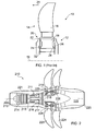
- the propeller assembly 10 comprises a hub 12 and a blade 14 having an aerofoil 16 and root 18.
- the blade 14 is configured to rotate about axis 19 with hub 12 on bearings (not shown) so as to provide a thrust in the direction indicated by arrow 21.
- Bearings 24 are provided such that the blade can be rotated about its longitudinal axis so as to provide a pitch control system.
- the root 18 is inserted into the hub 14 via an aperture 20 in the outer surface 22 of the hub 14 and the bearings 24 inserted between respective radially opposing faces 26, 28 of the hub 14 and root 18.
- the bearings 24 provide the rotational support required of the blade 14 and also act to prevent radial separation of the blade 14 and hub 12 during use. In this way, the bearings 24 act as a primary retention device.
- the secondary retention device in the embodiment shown in Figure 1 is a circular wire 32 which is fed into a channel formed from corresponding grooves in the facing surfaces of the hub 12 and the root 18. In the event of bearing failure, radial separation of the blade 14 and hub 12 is prevented by the wire.
- the wire 32 as a secondary retention device can be adequate, it relies on being correctly installed which requires a skilled operator and excessive amounts of time. Further, because the wire 32 is neither an integral part of the hub 12 nor the blade 14, it is subjected to relative movement between these components which can lead to vibration and wear problems. A further difficulty with this system arises due to the concealed location of the wire which makes inspection more troublesome.
- the present invention seeks to overcome some of the problems with known prior art.
- the present invention provides a blade assembly comprising: a hub which is rotatable about an axis; at least one blade having an aerofoil portion and a root, wherein the root is coupled to the hub using a primary retention device which prevents radial separation of the root and hub in normal use; and, a secondary retention device having a root part and a hub part, the root part being located radially inwards of the hub part in a retention cavity in use, wherein at least a portion of the root part enters the retention cavity via an interlock which prevents radial separation of the root and hub in the event of a primary retention device failure.
- Providing an interlock for a part of the root to pass through so as to be retained within a retention cavity allows a simple and mechanically robust way of providing a retention device.
- the interlock may comprise a retention aperture which overlaps a portion of the hub part when in normal use.
- the aperture may be substantially round.
- the aperture may be circular or oval.
- the aperture may include one or more notch or projection in or on a circumferential edge.
- the root part may include one or more notches or projections. The notches and projections of the respective aperture and root part may correspond to provide the interlock.
- the interlock may include a passageway through which the one or more projection can pass. The passageway may be in the root part or the hub part.
- the blade may have a longitudinal axis and the interlock may require the blade to be rotated approximately about the longitudinal axis of the blade to pass into the retention cavity via the interlock.
- the passageway may include at least two radially separated retention apertures and the root part may include at least two radially separated projections.
- the radially separated projections may be axially asymmetrical so as to provide a distributed overlap between the projections and the respective retention apertures when in use.
- the retention aperture may comprise a threaded portion which corresponds to a threaded portion on the root part.
- the root part may be suspended within the retention cavity in normal use. Suspended may be taken to mean that the root part is separated from the retention aperture so as to not contact in normal use.
- the interlock may be radially inwards of the primary retention device with respect to the rotational axis of the blade assembly.
- the interlock may be radially outwards of the primary retention device.
- the primary retention feature is a bearing arrangement.
- the separation of the root part and retention aperture in normal use may be less than 2.5mm.
- the separation may be in the range bounded by the values 1 mm and 3mm.
- the blade assembly may be configured such that the primary retention device can only be engaged once the root part has entered the retention cavity via the interlock.
- the present invention provides a method of manufacturing a blade assembly comprising: a hub which is rotatable about an axis; at least one blade having an aerofoil portion and a root, wherein the root is coupled to the hub using a primary retention device which prevents radial separation of the root and hub in normal use; and, a secondary retention device having a root part and a hub part, the root part being located radially inwards of the hub part in a retention cavity in use, wherein at least a portion of the root part enters the retention cavity via an interlock which prevents radial separation of the root and hub in the event of a primary retention device failure, the method comprising the steps of: presenting the root part to the interlock; passing the root portion through the interlock so that it resides within the retention cavity in normal use; engaging a primary retention device.
- Passing the root portion through the interlock may comprise rotating the root part about the approximate longitudinal axis of the blade.
- Rotating the root portion may require a continuous rotation through at least one complete revolution.
- Figure 2 shows a twin-spooled, contra-rotating propeller gas turbine engine 210 having a principal and rotational axis 209.
- the engine 210 comprises a core engine 211 having, in axial flow series, an air intake 212, an intermediate pressure compressor 214 (IPC), a high-pressure compressor 215 (HPC), combustion equipment 216, a high-pressure turbine 217 (HPT), intermediate pressure turbine 218 (IPT), a free power turbine 219 (FPT) and a core exhaust nozzle 220.
- a nacelle 221 generally surrounds the core engine 211 and defines the intake 212 and nozzle 220 and a core exhaust duct 222.
- the engine 210 also comprises two contra-rotating propellers 223, 224 attached to and driven by the free power turbine 219, which comprises contra-rotating blade arrays 225, 226.
- the gas turbine engine 210 works in a conventional manner so that air entering the intake 212 is accelerated and compressed by the IPC 214 and directed into the HPC 215 where further compression takes place.
- the compressed air exhausted from the HPC 215 is directed into the combustion equipment 216 where it is mixed with fuel and the mixture combusted.
- the resultant hot combustion products then expand through, and drive the high, low-pressure and free power turbines 217, 218, 219 before being exhausted through the nozzle 220 to provide some propulsive thrust.
- the high, low-pressure and free power turbines 217, 218, 219 respectively drive the high and intermediate pressure compressors 215, 214 and the propellers 223, 224 by suitable interconnecting shafts.
- FIG 3 shows a cross sectional representation of a blade assembly 310 according to the invention and which corresponds to either one of the propellers 223, 224 shown in Figure 2 .
- the blade assembly 310 includes a hub 312 and a blade 314.
- the blade 314 includes an aerofoil portion 318 and a root 320 which are connected in coaxial series via a shaft 321 which lies along the blades longitudinal axis .
- the root 320 is located within a retention cavity 322 of the hub 312 and includes in axial series extending from the shaft 321, a retention flange 324, body portion 326 and a pitch control shaft 328 which is rotatably connected to a pitch control actuator (not shown).
- the circumferential face of the retention flange 324 includes a threaded portion 330 which extends across the entirety of the circumferential face.
- the hub 312 includes a radially inner wall 332, side walls 334 and a radially outer wall 336 which provides the outwards facing surface of the hub 312.
- the root 320 is coupled to the hub 312 with a primary retention device, which, in the embodiment, is a bearing arrangement 344 located between two respective radailly opposing faces 340, 342 of the hub 312 and root 320.
- the bearing arrangement 344 acts to provide support for the blade 314 such that it can rotate around the longitudinal axis of the blade 314 and also retains the blade root 320 within the hub 312 so as to prevent radial separation of the two components under the centrifugal force which is exerted during normal use of the engine.
- the outer wall 336 of the hub includes a circular retention aperture 338 having a threaded circumferential face which corresponds to the threaded circumferential face 330 of the retention flange 324.
- the threaded arrangement between the retention aperture 338 and retention flange 324 provides a secondary retention device in the form of an interlock which allows the root 320 to pass into the retention cavity 322 via a passageway in a way which prevents radial separation of the root and hub in the event of a primary retention device failure.
- the retention flange 324 and retention aperture 338 can be threadingly engaged such that the root 320 enters the retention cavity 322 by being screwed through the outer wall 336 of the retention cavity 322. Once inside the retention cavity 322, direct radial extraction is restricted due to the overlap of the retention aperture provided between the inner surface dimension of the hub thread 330 and the outer surface dimension of the retention flange thread.
- the construction of the hub part 412 and root part 414 are similar with the exception that the retention aperture of the hub part thread is machined from a flange located on a side wall of the hub, and the root part 414 is in the form of a thread which is machined out of a flange located on the root body portion 420.
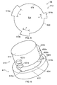
- Figure 5 shows a plan view of the hub 510 with a retention aperture 514 in the form of a circular bore in the outer wall 512 of the hub 510.
- the retention aperture 514 includes a plurality of arcuate cut outs 516a-c in the circumferential edge 518 of the outer wall 512 of the hub 510 so as to provide the aperture 514 with retention flanges 520.
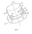
- Figure 6 shows a root 610 having a root portion 614 with a plurality of projections in the form of lugs 620a, 620b, 621 a, 621 b.
- the lugs correspond to the cut outs 616a, 616b in the hub outer wall 612 as described above and shown further in Figure 6 .
- the cut outs 616a, 616b and lugs 620a, 621 a, and 620b, 621 b are axially aligned so as to sit one above the other with respect to the longitudinal axis of the blade.
- the first significant factor is the rotational range required to adjust the blade pitch for normal use. This will typically be a range of approximately 90 degrees to move the blade between the so-called feathered to fine positions, but may include a larger range if reverse thrusting is required.
- the second factor is the magnitude of the centrifugal force that will act on the blade in the event of a failure of the primary retention device.
- the third factor is the position that the blade will come to rest in during a failure. This position is largely dependent on the shape and mass distribution of the blade which determines the centrifugal turning moment and aerodynamic load and thus the resting position. Other factors which may affect the resting position may be extraneous features such as a stop which prevents rotation of the blade.
- a stop may be in the form of a projection or pillar which extends from a suitable location on the hub part or root part, or other appropriate location.
- the first lugs inserted into and rotated through the channel defined by the retention flanges 622 before being inserted through the second, axially inner set of cut outs 718.
- the size of the lugs will depend ultimately on the force which they will experience during a failure of the primary retention device.
- projections which extend from the respective hub or root part will likely be in the order of a few millimetres depending on the engagement surface that is achieved between the root and hub parts.
Landscapes
- Engineering & Computer Science (AREA)
- Mechanical Engineering (AREA)
- General Engineering & Computer Science (AREA)
- Chemical & Material Sciences (AREA)
- Combustion & Propulsion (AREA)
- Aviation & Aerospace Engineering (AREA)
- Structures Of Non-Positive Displacement Pumps (AREA)
- Turbine Rotor Nozzle Sealing (AREA)
- Wind Motors (AREA)
Applications Claiming Priority (2)
| Application Number | Priority Date | Filing Date | Title |
|---|---|---|---|
| GB1109227.7A GB2491811B (en) | 2011-06-14 | 2011-06-14 | Mounting system |
| GBGB1113759.3A GB201113759D0 (en) | 2011-08-10 | 2011-08-10 | A retention device for a rotating blade |
Publications (2)
| Publication Number | Publication Date |
|---|---|
| EP2535519A2 true EP2535519A2 (fr) | 2012-12-19 |
| EP2535519A3 EP2535519A3 (fr) | 2014-11-12 |
Family
ID=46148766
Family Applications (1)
| Application Number | Title | Priority Date | Filing Date |
|---|---|---|---|
| EP12169972.2A Withdrawn EP2535519A3 (fr) | 2011-06-14 | 2012-05-30 | Dispositif de retenue pour pale rotative |
Country Status (4)
| Country | Link |
|---|---|
| US (1) | US9145776B2 (fr) |
| EP (1) | EP2535519A3 (fr) |
| JP (1) | JP2013002445A (fr) |
| CA (1) | CA2778569A1 (fr) |
Cited By (10)
| Publication number | Priority date | Publication date | Assignee | Title |
|---|---|---|---|---|
| EP2808251A1 (fr) * | 2013-05-31 | 2014-12-03 | SZ DJI Technology Co., Ltd. | Rotor autoserrant |
| CN106286390A (zh) * | 2015-06-23 | 2017-01-04 | 通用电气公司 | 用于涡轮发动机的耳轴保持件 |
| FR3040191A1 (fr) * | 2015-08-20 | 2017-02-24 | Airbus Operations Sas | Helice pour turbomachine d'aeronef comprenant des moyens ameliores de retention radiale de pale d'helice |
| EP3179085A1 (fr) * | 2015-12-07 | 2017-06-14 | Rolls-Royce plc | Appareil à aube mobile soufflante |
| GB2551631A (en) * | 2016-04-28 | 2017-12-27 | Airbus Operations Sas | Propeller for an aircraft turbo engine, including safety means for controlling blade angle of attack |
| WO2021157675A1 (fr) * | 2020-02-04 | 2021-08-12 | Hapsmobile Inc. | Accoupleur pale-moyeu d'hélice pour véhicule aérien sans pilote |
| WO2021214399A1 (fr) * | 2020-04-23 | 2021-10-28 | Safran Aircraft Engines | Pivot d'aube à orientation réglable et à intégrité sauvegardée pour moyeu de soufflante de turbomachine |
| WO2023089274A1 (fr) * | 2021-11-19 | 2023-05-25 | Safran Aircraft Engines | Module de montage d'une aube de soufflante de turbomachine |
| WO2026033179A1 (fr) | 2024-08-07 | 2026-02-12 | Safran Aircraft Engines | Aube a calage variable pour une turbomachine |
| WO2026033178A1 (fr) | 2024-08-07 | 2026-02-12 | Safran Aircraft Engines | Aube a calage variable pour une turbomachine |
Families Citing this family (19)
| Publication number | Priority date | Publication date | Assignee | Title |
|---|---|---|---|---|
| GB201211133D0 (en) * | 2012-06-22 | 2012-08-08 | Rolls Royce Plc | A catcher ring arrangement |
| FR3017667B1 (fr) * | 2014-02-14 | 2019-05-03 | Safran Aircraft Engines | Dispositif pour une helice non carenee a pales a calage variable d'une turbomachine |
| US9869190B2 (en) | 2014-05-30 | 2018-01-16 | General Electric Company | Variable-pitch rotor with remote counterweights |
| FR3027947B1 (fr) * | 2014-10-31 | 2021-05-14 | Snecma | Anneau d'helice comprenant des logements radiaux de section ovoide |
| US10072510B2 (en) | 2014-11-21 | 2018-09-11 | General Electric Company | Variable pitch fan for gas turbine engine and method of assembling the same |
| US10100653B2 (en) | 2015-10-08 | 2018-10-16 | General Electric Company | Variable pitch fan blade retention system |
| CN108194225B (zh) * | 2017-11-20 | 2019-06-07 | 北京动力机械研究所 | 一种小推力高性能低成本后置涡扇发动机 |
| US12491987B2 (en) | 2020-07-24 | 2025-12-09 | Safran Aircraft Engines | Aircraft turbine engine comprising variable-pitch propeller vanes |
| EP4185523B1 (fr) | 2020-07-24 | 2024-06-26 | Safran Aircraft Engines | Système de commande du calage angulaire d'une aube d'helice pour une turbomachine d'aeronef |
| CN116097005A (zh) * | 2020-07-24 | 2023-05-09 | 赛峰飞机发动机公司 | 包括可变桨距螺旋桨轮叶的飞行器涡轮发动机 |
| WO2022018356A1 (fr) | 2020-07-24 | 2022-01-27 | Safran Aircraft Engines | Ensemble comportant une aube et un systeme de calage angulaire de l'aube |
| EP4185520B1 (fr) * | 2020-07-24 | 2024-05-08 | Safran Aircraft Engines | Système de commande du calage angulaire d'une aube d'helice pour une turbomachine d'aeronef |
| US11674435B2 (en) | 2021-06-29 | 2023-06-13 | General Electric Company | Levered counterweight feathering system |
| US11795964B2 (en) | 2021-07-16 | 2023-10-24 | General Electric Company | Levered counterweight feathering system |
| DE102022101781A1 (de) * | 2022-01-26 | 2023-07-27 | Ebm-Papst Mulfingen Gmbh & Co. Kg | Lüfterbaugruppe |
| US12601271B2 (en) | 2022-10-21 | 2026-04-14 | General Electric Company | Variable pitch fan of a gas turbine engine |
| US12264590B2 (en) | 2023-08-08 | 2025-04-01 | General Electric Company | Fan assembly for an engine having redundant trunnion retention |
| FR3156753A1 (fr) * | 2023-12-13 | 2025-06-20 | Airbus Operations (S.A.S.) | Hélice comprenant au moins un système de maintien de pale comportant au moins une gorge transversale |
| US12420909B1 (en) | 2025-03-04 | 2025-09-23 | General Electric Company | Airfoil assembly having a composite spar |
Family Cites Families (8)
| Publication number | Priority date | Publication date | Assignee | Title |
|---|---|---|---|---|
| GB825303A (en) * | 1957-04-15 | 1959-12-16 | Rotol Ltd | Improvements in or relating to variable pitch propellers |
| US5263898A (en) | 1988-12-14 | 1993-11-23 | General Electric Company | Propeller blade retention system |
| GB9616170D0 (en) | 1996-08-01 | 1996-09-11 | Timken The Company | Bearing assembly |
| US6015264A (en) | 1997-08-15 | 2000-01-18 | United Technologies Corporation | Preloaded retention assembly for aircraft propeller blade retention |
| DE19753927C2 (de) * | 1997-12-05 | 2000-05-25 | Peter Mueller | Verstellpropeller, insbesondere für Sportboote |
| GB0712561D0 (en) | 2007-06-28 | 2007-08-08 | Rolls Royce Plc | A blade mounting |
| FR2942454B1 (fr) | 2009-02-23 | 2012-09-14 | Airbus France | Dispositif de retenue d'aube pour helice de turbomachine. |
| FR2943312B1 (fr) * | 2009-03-23 | 2011-05-27 | Snecma | Helice non carenee a pales a calage variable pour une turbomachine |
-
2012
- 2012-05-30 US US13/483,460 patent/US9145776B2/en active Active
- 2012-05-30 EP EP12169972.2A patent/EP2535519A3/fr not_active Withdrawn
- 2012-06-01 CA CA2778569A patent/CA2778569A1/fr not_active Abandoned
- 2012-06-14 JP JP2012134556A patent/JP2013002445A/ja active Pending
Non-Patent Citations (1)
| Title |
|---|
| None |
Cited By (31)
| Publication number | Priority date | Publication date | Assignee | Title |
|---|---|---|---|---|
| US10160538B2 (en) | 2013-05-31 | 2018-12-25 | SZ DJI Technology Co., Ltd. | Self-tightening rotor |
| US9057273B2 (en) | 2013-05-31 | 2015-06-16 | SZ DJI Technology Co., Ltd | Self-tightening rotor |
| US9284040B2 (en) | 2013-05-31 | 2016-03-15 | SZ DJI Technology Co., Ltd | Self-tightening rotor |
| US10745119B2 (en) | 2013-05-31 | 2020-08-18 | SZ DJI Technology Co., Ltd. | Self-tightening rotor |
| US11267565B2 (en) | 2013-05-31 | 2022-03-08 | SZ DJI Technology Co., Ltd. | Self-tightening rotor |
| US10196138B2 (en) | 2013-05-31 | 2019-02-05 | SZ DJI Technology Co., Ltd. | Self-tightening rotor |
| US9630703B2 (en) | 2013-05-31 | 2017-04-25 | SZ DJI Technology Co., Ltd | Self-tightening rotor |
| EP2808251A1 (fr) * | 2013-05-31 | 2014-12-03 | SZ DJI Technology Co., Ltd. | Rotor autoserrant |
| CN106286390A (zh) * | 2015-06-23 | 2017-01-04 | 通用电气公司 | 用于涡轮发动机的耳轴保持件 |
| US10077674B2 (en) | 2015-06-23 | 2018-09-18 | General Electric Company | Trunnion retention for a turbine engine |
| US12134971B2 (en) | 2015-06-23 | 2024-11-05 | General Electric Company | Trunnion retention for a turbine engine |
| EP3109481A3 (fr) * | 2015-06-23 | 2017-03-01 | General Electric Company | Rétention de tourillon pour un moteur à turbine |
| CN106286390B (zh) * | 2015-06-23 | 2019-09-17 | 通用电气公司 | 用于涡轮发动机的耳轴保持件 |
| US11053812B2 (en) | 2015-06-23 | 2021-07-06 | General Electric Company | Trunnion retention for a turbine engine |
| FR3040191A1 (fr) * | 2015-08-20 | 2017-02-24 | Airbus Operations Sas | Helice pour turbomachine d'aeronef comprenant des moyens ameliores de retention radiale de pale d'helice |
| EP3179085A1 (fr) * | 2015-12-07 | 2017-06-14 | Rolls-Royce plc | Appareil à aube mobile soufflante |
| US10472978B2 (en) | 2015-12-07 | 2019-11-12 | Rolls-Royce Plc | Fan blade apparatus |
| GB2551631A (en) * | 2016-04-28 | 2017-12-27 | Airbus Operations Sas | Propeller for an aircraft turbo engine, including safety means for controlling blade angle of attack |
| GB2551631B (en) * | 2016-04-28 | 2021-03-03 | Airbus Operations Sas | Propeller for an aircraft turbo engine, including safety means for controlling blade angle of attack |
| WO2021157675A1 (fr) * | 2020-02-04 | 2021-08-12 | Hapsmobile Inc. | Accoupleur pale-moyeu d'hélice pour véhicule aérien sans pilote |
| US11708148B2 (en) | 2020-04-23 | 2023-07-25 | Safran Aircraft Engines | Blade pivot with adjustable orientation and protected integrity for a turbomachine fan hub |
| WO2021214399A1 (fr) * | 2020-04-23 | 2021-10-28 | Safran Aircraft Engines | Pivot d'aube à orientation réglable et à intégrité sauvegardée pour moyeu de soufflante de turbomachine |
| FR3109569A1 (fr) * | 2020-04-23 | 2021-10-29 | Safran Aircraft Engines | Pivot d’aube à orientation réglable et à intégrité sauvegardée pour moyeu de soufflante de turbomachine |
| FR3129432A1 (fr) * | 2021-11-19 | 2023-05-26 | Safran Aircraft Engines | Module de montage d’une aube de soufflante de turbomachine |
| WO2023089274A1 (fr) * | 2021-11-19 | 2023-05-25 | Safran Aircraft Engines | Module de montage d'une aube de soufflante de turbomachine |
| US20250020139A1 (en) * | 2021-11-19 | 2025-01-16 | Safran Aircraft Engines | Module for mounting a turbomachine fan blade |
| US12313081B2 (en) * | 2021-11-19 | 2025-05-27 | Safran Aircraft Engines | Module for mounting a turbomachine fan blade |
| WO2026033179A1 (fr) | 2024-08-07 | 2026-02-12 | Safran Aircraft Engines | Aube a calage variable pour une turbomachine |
| WO2026033178A1 (fr) | 2024-08-07 | 2026-02-12 | Safran Aircraft Engines | Aube a calage variable pour une turbomachine |
| FR3165469A1 (fr) * | 2024-08-07 | 2026-02-13 | Safran Aircraft Engines | Aube a calage variable pour une turbomachine |
| FR3165467A1 (fr) * | 2024-08-07 | 2026-02-13 | Safran Aircraft Engines | Aube a calage variable pour une turbomachine |
Also Published As
| Publication number | Publication date |
|---|---|
| JP2013002445A (ja) | 2013-01-07 |
| US9145776B2 (en) | 2015-09-29 |
| CA2778569A1 (fr) | 2012-12-14 |
| EP2535519A3 (fr) | 2014-11-12 |
| US20120321476A1 (en) | 2012-12-20 |
Similar Documents
| Publication | Publication Date | Title |
|---|---|---|
| US9145776B2 (en) | Retention device for a rotating blade | |
| EP2677121B1 (fr) | Anneau receveur | |
| EP2635781B1 (fr) | Turbocompresseur à gaz d'échappement avec moyens permettant la fixation axiale de l'arbre en cas de rupture de la roue de compresseur | |
| EP3109481A2 (fr) | Rétention de tourillon pour un moteur à turbine | |
| US20190345876A1 (en) | Method of positioning two parts relative to each other in a formlocking connection, a formlocking device and gas turbine engine | |
| EP3533973B1 (fr) | Ensemble de bras d'aube à retenue automatique pour moteur de turbine à gaz | |
| US10260348B2 (en) | Compressor for an axial turbine engine with double contra-rotating rotors | |
| US20220018357A1 (en) | Blade pivot of adjustable orientation and of reduced bulk for a turbomachine fan hub | |
| EP3074605B1 (fr) | Pale de ventilateur comportant un couvercle de pale de ventilateur segmenté | |
| US20180016937A1 (en) | Gas turbine and method for protecting a gas turbine in case of a shaft break | |
| EP3514327A1 (fr) | Pale avec pied asymétrique pour moteur de turbine à gaz | |
| WO2016205013A1 (fr) | Ensemble palier | |
| EP3170982A1 (fr) | Ensemble rotor pour utilisation dans turboréacteur à double flux et son procédé d'assemblage | |
| EP3219931B1 (fr) | Agencement d'aube distributrice et moteur à turbine à gaz associé | |
| EP2946117B1 (fr) | Agencement d'aube à surface variable avec bras de levier et moteur à turbine équipé de celui-ci | |
| EP3018301B1 (fr) | Bras d'aube à fente de rétention inclinée | |
| US12415597B2 (en) | Propeller for a turbine engine of an aircraft with a variable-pitch vane and a geared counterweight device | |
| US11060419B2 (en) | Planetary gear drive and aircraft gas turbine with a planetary gear drive | |
| CN108661727B (zh) | 涡轮发动机轴承组件及其组装方法 | |
| EP2935786A1 (fr) | Disque de turbine doté d'une concentration de contraintes de col réduite | |
| EP3059396B1 (fr) | Moteur à turbine à gaz et configurations de turbine | |
| US20190085903A1 (en) | Bearing assembly | |
| EP3053701A1 (fr) | Manchon conique sans brides et procédé de réparation |
Legal Events
| Date | Code | Title | Description |
|---|---|---|---|
| PUAI | Public reference made under article 153(3) epc to a published international application that has entered the european phase |
Free format text: ORIGINAL CODE: 0009012 |
|
| AK | Designated contracting states |
Kind code of ref document: A2 Designated state(s): AL AT BE BG CH CY CZ DE DK EE ES FI FR GB GR HR HU IE IS IT LI LT LU LV MC MK MT NL NO PL PT RO RS SE SI SK SM TR |
|
| AX | Request for extension of the european patent |
Extension state: BA ME |
|
| PUAL | Search report despatched |
Free format text: ORIGINAL CODE: 0009013 |
|
| AK | Designated contracting states |
Kind code of ref document: A3 Designated state(s): AL AT BE BG CH CY CZ DE DK EE ES FI FR GB GR HR HU IE IS IT LI LT LU LV MC MK MT NL NO PL PT RO RS SE SI SK SM TR |
|
| AX | Request for extension of the european patent |
Extension state: BA ME |
|
| RIC1 | Information provided on ipc code assigned before grant |
Ipc: F02K 3/072 20060101ALI20141003BHEP Ipc: F02C 6/20 20060101ALI20141003BHEP Ipc: F01D 7/00 20060101ALI20141003BHEP Ipc: F01D 5/30 20060101AFI20141003BHEP Ipc: F01D 21/04 20060101ALI20141003BHEP Ipc: B64C 11/06 20060101ALI20141003BHEP |
|
| 17P | Request for examination filed |
Effective date: 20150511 |
|
| RBV | Designated contracting states (corrected) |
Designated state(s): AL AT BE BG CH CY CZ DE DK EE ES FI FR GB GR HR HU IE IS IT LI LT LU LV MC MK MT NL NO PL PT RO RS SE SI SK SM TR |
|
| RAP1 | Party data changed (applicant data changed or rights of an application transferred) |
Owner name: ROLLS-ROYCE PLC |
|
| STAA | Information on the status of an ep patent application or granted ep patent |
Free format text: STATUS: EXAMINATION IS IN PROGRESS |
|
| 17Q | First examination report despatched |
Effective date: 20170731 |
|
| RAP1 | Party data changed (applicant data changed or rights of an application transferred) |
Owner name: ROLLS-ROYCE PLC |
|
| STAA | Information on the status of an ep patent application or granted ep patent |
Free format text: STATUS: THE APPLICATION HAS BEEN WITHDRAWN |
|
| 18W | Application withdrawn |
Effective date: 20200928 |