EP2535532A1 - Erweiterte ASU- und HRSG-Integration für eine verbesserte Wirksamkeit des integrierten Gasifizierungs-Kombinationskreislaufs - Google Patents
Erweiterte ASU- und HRSG-Integration für eine verbesserte Wirksamkeit des integrierten Gasifizierungs-Kombinationskreislaufs Download PDFInfo
- Publication number
- EP2535532A1 EP2535532A1 EP12182946A EP12182946A EP2535532A1 EP 2535532 A1 EP2535532 A1 EP 2535532A1 EP 12182946 A EP12182946 A EP 12182946A EP 12182946 A EP12182946 A EP 12182946A EP 2535532 A1 EP2535532 A1 EP 2535532A1
- Authority
- EP
- European Patent Office
- Prior art keywords
- stream
- gas product
- product stream
- heat
- syngas
- Prior art date
- Legal status (The legal status is an assumption and is not a legal conclusion. Google has not performed a legal analysis and makes no representation as to the accuracy of the status listed.)
- Withdrawn
Links
- 238000002309 gasification Methods 0.000 title claims abstract description 16
- 230000010354 integration Effects 0.000 title description 5
- IJGRMHOSHXDMSA-UHFFFAOYSA-N Atomic nitrogen Chemical compound N#N IJGRMHOSHXDMSA-UHFFFAOYSA-N 0.000 claims abstract description 92
- 239000000446 fuel Substances 0.000 claims abstract description 41
- 229910001873 dinitrogen Inorganic materials 0.000 claims abstract description 38
- MYMOFIZGZYHOMD-UHFFFAOYSA-N Dioxygen Chemical compound O=O MYMOFIZGZYHOMD-UHFFFAOYSA-N 0.000 claims abstract description 30
- 229910001882 dioxygen Inorganic materials 0.000 claims abstract description 29
- 239000000203 mixture Substances 0.000 claims abstract description 24
- 239000003245 coal Substances 0.000 claims abstract description 16
- 238000010438 heat treatment Methods 0.000 claims abstract description 14
- 230000001172 regenerating effect Effects 0.000 claims abstract description 11
- 238000000926 separation method Methods 0.000 claims abstract description 8
- QVGXLLKOCUKJST-UHFFFAOYSA-N atomic oxygen Chemical compound [O] QVGXLLKOCUKJST-UHFFFAOYSA-N 0.000 claims description 8
- 229910052760 oxygen Inorganic materials 0.000 claims description 8
- 239000001301 oxygen Substances 0.000 claims description 8
- 238000003303 reheating Methods 0.000 claims 2
- 239000000047 product Substances 0.000 description 58
- 239000007789 gas Substances 0.000 description 41
- 229910052757 nitrogen Inorganic materials 0.000 description 26
- 238000002485 combustion reaction Methods 0.000 description 12
- 238000000034 method Methods 0.000 description 10
- 238000011144 upstream manufacturing Methods 0.000 description 7
- 239000002253 acid Substances 0.000 description 5
- CURLTUGMZLYLDI-UHFFFAOYSA-N Carbon dioxide Chemical compound O=C=O CURLTUGMZLYLDI-UHFFFAOYSA-N 0.000 description 4
- 230000005611 electricity Effects 0.000 description 4
- 238000011084 recovery Methods 0.000 description 4
- UGFAIRIUMAVXCW-UHFFFAOYSA-N Carbon monoxide Chemical compound [O+]#[C-] UGFAIRIUMAVXCW-UHFFFAOYSA-N 0.000 description 3
- QGZKDVFQNNGYKY-UHFFFAOYSA-N Ammonia Chemical compound N QGZKDVFQNNGYKY-UHFFFAOYSA-N 0.000 description 2
- NINIDFKCEFEMDL-UHFFFAOYSA-N Sulfur Chemical compound [S] NINIDFKCEFEMDL-UHFFFAOYSA-N 0.000 description 2
- 230000009286 beneficial effect Effects 0.000 description 2
- 229910002092 carbon dioxide Inorganic materials 0.000 description 2
- 239000001569 carbon dioxide Substances 0.000 description 2
- 239000003085 diluting agent Substances 0.000 description 2
- 239000003546 flue gas Substances 0.000 description 2
- 239000001257 hydrogen Substances 0.000 description 2
- 229910052739 hydrogen Inorganic materials 0.000 description 2
- 238000012986 modification Methods 0.000 description 2
- 230000004048 modification Effects 0.000 description 2
- 238000010248 power generation Methods 0.000 description 2
- 239000011593 sulfur Substances 0.000 description 2
- UFHFLCQGNIYNRP-UHFFFAOYSA-N Hydrogen Chemical compound [H][H] UFHFLCQGNIYNRP-UHFFFAOYSA-N 0.000 description 1
- 230000006978 adaptation Effects 0.000 description 1
- 229910021529 ammonia Inorganic materials 0.000 description 1
- 239000006227 byproduct Substances 0.000 description 1
- 229910002091 carbon monoxide Inorganic materials 0.000 description 1
- 238000006243 chemical reaction Methods 0.000 description 1
- 239000007795 chemical reaction product Substances 0.000 description 1
- 238000004140 cleaning Methods 0.000 description 1
- 238000007906 compression Methods 0.000 description 1
- 238000005516 engineering process Methods 0.000 description 1
- 239000012530 fluid Substances 0.000 description 1
- 239000002737 fuel gas Substances 0.000 description 1
- 239000005431 greenhouse gas Substances 0.000 description 1
- 150000002431 hydrogen Chemical class 0.000 description 1
- 239000007788 liquid Substances 0.000 description 1
- 238000004519 manufacturing process Methods 0.000 description 1
- 229910052751 metal Inorganic materials 0.000 description 1
- 239000002184 metal Substances 0.000 description 1
- 150000002739 metals Chemical class 0.000 description 1
- 229920006395 saturated elastomer Polymers 0.000 description 1
- 239000000126 substance Substances 0.000 description 1
- 229910052717 sulfur Inorganic materials 0.000 description 1
- 150000003464 sulfur compounds Chemical class 0.000 description 1
- RAHZWNYVWXNFOC-UHFFFAOYSA-N sulfur dioxide Inorganic materials O=S=O RAHZWNYVWXNFOC-UHFFFAOYSA-N 0.000 description 1
- 239000002918 waste heat Substances 0.000 description 1
- XLYOFNOQVPJJNP-UHFFFAOYSA-N water Substances O XLYOFNOQVPJJNP-UHFFFAOYSA-N 0.000 description 1
Images


Classifications
-
- F—MECHANICAL ENGINEERING; LIGHTING; HEATING; WEAPONS; BLASTING
- F02—COMBUSTION ENGINES; HOT-GAS OR COMBUSTION-PRODUCT ENGINE PLANTS
- F02C—GAS-TURBINE PLANTS; AIR INTAKES FOR JET-PROPULSION PLANTS; CONTROLLING FUEL SUPPLY IN AIR-BREATHING JET-PROPULSION PLANTS
- F02C3/00—Gas-turbine plants characterised by the use of combustion products as the working fluid
- F02C3/20—Gas-turbine plants characterised by the use of combustion products as the working fluid using a special fuel, oxidant, or dilution fluid to generate the combustion products
- F02C3/26—Gas-turbine plants characterised by the use of combustion products as the working fluid using a special fuel, oxidant, or dilution fluid to generate the combustion products the fuel or oxidant being solid or pulverulent, e.g. in slurry or suspension
- F02C3/28—Gas-turbine plants characterised by the use of combustion products as the working fluid using a special fuel, oxidant, or dilution fluid to generate the combustion products the fuel or oxidant being solid or pulverulent, e.g. in slurry or suspension using a separate gas producer for gasifying the fuel before combustion
-
- F—MECHANICAL ENGINEERING; LIGHTING; HEATING; WEAPONS; BLASTING
- F01—MACHINES OR ENGINES IN GENERAL; ENGINE PLANTS IN GENERAL; STEAM ENGINES
- F01K—STEAM ENGINE PLANTS; STEAM ACCUMULATORS; ENGINE PLANTS NOT OTHERWISE PROVIDED FOR; ENGINES USING SPECIAL WORKING FLUIDS OR CYCLES
- F01K23/00—Plants characterised by more than one engine delivering power external to the plant, the engines being driven by different fluids
- F01K23/02—Plants characterised by more than one engine delivering power external to the plant, the engines being driven by different fluids the engine cycles being thermally coupled
- F01K23/06—Plants characterised by more than one engine delivering power external to the plant, the engines being driven by different fluids the engine cycles being thermally coupled combustion heat from one cycle heating the fluid in another cycle
- F01K23/067—Plants characterised by more than one engine delivering power external to the plant, the engines being driven by different fluids the engine cycles being thermally coupled combustion heat from one cycle heating the fluid in another cycle the combustion heat coming from a gasification or pyrolysis process, e.g. coal gasification
- F01K23/068—Plants characterised by more than one engine delivering power external to the plant, the engines being driven by different fluids the engine cycles being thermally coupled combustion heat from one cycle heating the fluid in another cycle the combustion heat coming from a gasification or pyrolysis process, e.g. coal gasification in combination with an oxygen producing plant, e.g. an air separation plant
-
- F—MECHANICAL ENGINEERING; LIGHTING; HEATING; WEAPONS; BLASTING
- F01—MACHINES OR ENGINES IN GENERAL; ENGINE PLANTS IN GENERAL; STEAM ENGINES
- F01K—STEAM ENGINE PLANTS; STEAM ACCUMULATORS; ENGINE PLANTS NOT OTHERWISE PROVIDED FOR; ENGINES USING SPECIAL WORKING FLUIDS OR CYCLES
- F01K23/00—Plants characterised by more than one engine delivering power external to the plant, the engines being driven by different fluids
- F01K23/02—Plants characterised by more than one engine delivering power external to the plant, the engines being driven by different fluids the engine cycles being thermally coupled
- F01K23/06—Plants characterised by more than one engine delivering power external to the plant, the engines being driven by different fluids the engine cycles being thermally coupled combustion heat from one cycle heating the fluid in another cycle
- F01K23/10—Plants characterised by more than one engine delivering power external to the plant, the engines being driven by different fluids the engine cycles being thermally coupled combustion heat from one cycle heating the fluid in another cycle with exhaust fluid of one cycle heating the fluid in another cycle
-
- F—MECHANICAL ENGINEERING; LIGHTING; HEATING; WEAPONS; BLASTING
- F02—COMBUSTION ENGINES; HOT-GAS OR COMBUSTION-PRODUCT ENGINE PLANTS
- F02C—GAS-TURBINE PLANTS; AIR INTAKES FOR JET-PROPULSION PLANTS; CONTROLLING FUEL SUPPLY IN AIR-BREATHING JET-PROPULSION PLANTS
- F02C6/00—Plural gas-turbine plants; Combinations of gas-turbine plants with other apparatus; Adaptations of gas-turbine plants for special use
- F02C6/18—Plural gas-turbine plants; Combinations of gas-turbine plants with other apparatus; Adaptations of gas-turbine plants for special use using the waste heat of gas-turbine plants outside the plants themselves, e.g. gas-turbine power heat plants
-
- F—MECHANICAL ENGINEERING; LIGHTING; HEATING; WEAPONS; BLASTING
- F25—REFRIGERATION OR COOLING; COMBINED HEATING AND REFRIGERATION SYSTEMS; HEAT PUMP SYSTEMS; MANUFACTURE OR STORAGE OF ICE; LIQUEFACTION SOLIDIFICATION OF GASES
- F25J—LIQUEFACTION, SOLIDIFICATION OR SEPARATION OF GASES OR GASEOUS OR LIQUEFIED GASEOUS MIXTURES BY PRESSURE AND COLD TREATMENT OR BY BRINGING THEM INTO THE SUPERCRITICAL STATE
- F25J3/00—Processes or apparatus for separating the constituents of gaseous or liquefied gaseous mixtures involving the use of liquefaction or solidification
- F25J3/02—Processes or apparatus for separating the constituents of gaseous or liquefied gaseous mixtures involving the use of liquefaction or solidification by rectification, i.e. by continuous interchange of heat and material between a vapour stream and a liquid stream
- F25J3/04—Processes or apparatus for separating the constituents of gaseous or liquefied gaseous mixtures involving the use of liquefaction or solidification by rectification, i.e. by continuous interchange of heat and material between a vapour stream and a liquid stream for air
- F25J3/04006—Providing pressurised feed air or process streams within or from the air fractionation unit
- F25J3/04012—Providing pressurised feed air or process streams within or from the air fractionation unit by compression of warm gaseous streams; details of intake or interstage cooling
- F25J3/04018—Providing pressurised feed air or process streams within or from the air fractionation unit by compression of warm gaseous streams; details of intake or interstage cooling of main feed air
-
- F—MECHANICAL ENGINEERING; LIGHTING; HEATING; WEAPONS; BLASTING
- F25—REFRIGERATION OR COOLING; COMBINED HEATING AND REFRIGERATION SYSTEMS; HEAT PUMP SYSTEMS; MANUFACTURE OR STORAGE OF ICE; LIQUEFACTION SOLIDIFICATION OF GASES
- F25J—LIQUEFACTION, SOLIDIFICATION OR SEPARATION OF GASES OR GASEOUS OR LIQUEFIED GASEOUS MIXTURES BY PRESSURE AND COLD TREATMENT OR BY BRINGING THEM INTO THE SUPERCRITICAL STATE
- F25J3/00—Processes or apparatus for separating the constituents of gaseous or liquefied gaseous mixtures involving the use of liquefaction or solidification
- F25J3/02—Processes or apparatus for separating the constituents of gaseous or liquefied gaseous mixtures involving the use of liquefaction or solidification by rectification, i.e. by continuous interchange of heat and material between a vapour stream and a liquid stream
- F25J3/04—Processes or apparatus for separating the constituents of gaseous or liquefied gaseous mixtures involving the use of liquefaction or solidification by rectification, i.e. by continuous interchange of heat and material between a vapour stream and a liquid stream for air
- F25J3/04006—Providing pressurised feed air or process streams within or from the air fractionation unit
- F25J3/04109—Arrangements of compressors and /or their drivers
- F25J3/04115—Arrangements of compressors and /or their drivers characterised by the type of prime driver, e.g. hot gas expander
- F25J3/04127—Gas turbine as the prime mechanical driver
-
- F—MECHANICAL ENGINEERING; LIGHTING; HEATING; WEAPONS; BLASTING
- F25—REFRIGERATION OR COOLING; COMBINED HEATING AND REFRIGERATION SYSTEMS; HEAT PUMP SYSTEMS; MANUFACTURE OR STORAGE OF ICE; LIQUEFACTION SOLIDIFICATION OF GASES
- F25J—LIQUEFACTION, SOLIDIFICATION OR SEPARATION OF GASES OR GASEOUS OR LIQUEFIED GASEOUS MIXTURES BY PRESSURE AND COLD TREATMENT OR BY BRINGING THEM INTO THE SUPERCRITICAL STATE
- F25J3/00—Processes or apparatus for separating the constituents of gaseous or liquefied gaseous mixtures involving the use of liquefaction or solidification
- F25J3/02—Processes or apparatus for separating the constituents of gaseous or liquefied gaseous mixtures involving the use of liquefaction or solidification by rectification, i.e. by continuous interchange of heat and material between a vapour stream and a liquid stream
- F25J3/04—Processes or apparatus for separating the constituents of gaseous or liquefied gaseous mixtures involving the use of liquefaction or solidification by rectification, i.e. by continuous interchange of heat and material between a vapour stream and a liquid stream for air
- F25J3/04521—Coupling of the air fractionation unit to an air gas-consuming unit, so-called integrated processes
- F25J3/04527—Integration with an oxygen consuming unit, e.g. glass facility, waste incineration or oxygen based processes in general
- F25J3/04539—Integration with an oxygen consuming unit, e.g. glass facility, waste incineration or oxygen based processes in general for the H2/CO synthesis by partial oxidation or oxygen consuming reforming processes of fuels
- F25J3/04545—Integration with an oxygen consuming unit, e.g. glass facility, waste incineration or oxygen based processes in general for the H2/CO synthesis by partial oxidation or oxygen consuming reforming processes of fuels for the gasification of solid or heavy liquid fuels, e.g. integrated gasification combined cycle [IGCC]
-
- F—MECHANICAL ENGINEERING; LIGHTING; HEATING; WEAPONS; BLASTING
- F25—REFRIGERATION OR COOLING; COMBINED HEATING AND REFRIGERATION SYSTEMS; HEAT PUMP SYSTEMS; MANUFACTURE OR STORAGE OF ICE; LIQUEFACTION SOLIDIFICATION OF GASES
- F25J—LIQUEFACTION, SOLIDIFICATION OR SEPARATION OF GASES OR GASEOUS OR LIQUEFIED GASEOUS MIXTURES BY PRESSURE AND COLD TREATMENT OR BY BRINGING THEM INTO THE SUPERCRITICAL STATE
- F25J3/00—Processes or apparatus for separating the constituents of gaseous or liquefied gaseous mixtures involving the use of liquefaction or solidification
- F25J3/02—Processes or apparatus for separating the constituents of gaseous or liquefied gaseous mixtures involving the use of liquefaction or solidification by rectification, i.e. by continuous interchange of heat and material between a vapour stream and a liquid stream
- F25J3/04—Processes or apparatus for separating the constituents of gaseous or liquefied gaseous mixtures involving the use of liquefaction or solidification by rectification, i.e. by continuous interchange of heat and material between a vapour stream and a liquid stream for air
- F25J3/04521—Coupling of the air fractionation unit to an air gas-consuming unit, so-called integrated processes
- F25J3/04563—Integration with a nitrogen consuming unit, e.g. for purging, inerting, cooling or heating
- F25J3/04575—Integration with a nitrogen consuming unit, e.g. for purging, inerting, cooling or heating for a gas expansion plant, e.g. dilution of the combustion gas in a gas turbine
-
- F—MECHANICAL ENGINEERING; LIGHTING; HEATING; WEAPONS; BLASTING
- F25—REFRIGERATION OR COOLING; COMBINED HEATING AND REFRIGERATION SYSTEMS; HEAT PUMP SYSTEMS; MANUFACTURE OR STORAGE OF ICE; LIQUEFACTION SOLIDIFICATION OF GASES
- F25J—LIQUEFACTION, SOLIDIFICATION OR SEPARATION OF GASES OR GASEOUS OR LIQUEFIED GASEOUS MIXTURES BY PRESSURE AND COLD TREATMENT OR BY BRINGING THEM INTO THE SUPERCRITICAL STATE
- F25J3/00—Processes or apparatus for separating the constituents of gaseous or liquefied gaseous mixtures involving the use of liquefaction or solidification
- F25J3/02—Processes or apparatus for separating the constituents of gaseous or liquefied gaseous mixtures involving the use of liquefaction or solidification by rectification, i.e. by continuous interchange of heat and material between a vapour stream and a liquid stream
- F25J3/04—Processes or apparatus for separating the constituents of gaseous or liquefied gaseous mixtures involving the use of liquefaction or solidification by rectification, i.e. by continuous interchange of heat and material between a vapour stream and a liquid stream for air
- F25J3/04521—Coupling of the air fractionation unit to an air gas-consuming unit, so-called integrated processes
- F25J3/04593—The air gas consuming unit is also fed by an air stream
- F25J3/04606—Partially integrated air feed compression, i.e. independent MAC for the air fractionation unit plus additional air feed from the air gas consuming unit
-
- F—MECHANICAL ENGINEERING; LIGHTING; HEATING; WEAPONS; BLASTING
- F25—REFRIGERATION OR COOLING; COMBINED HEATING AND REFRIGERATION SYSTEMS; HEAT PUMP SYSTEMS; MANUFACTURE OR STORAGE OF ICE; LIQUEFACTION SOLIDIFICATION OF GASES
- F25J—LIQUEFACTION, SOLIDIFICATION OR SEPARATION OF GASES OR GASEOUS OR LIQUEFIED GASEOUS MIXTURES BY PRESSURE AND COLD TREATMENT OR BY BRINGING THEM INTO THE SUPERCRITICAL STATE
- F25J3/00—Processes or apparatus for separating the constituents of gaseous or liquefied gaseous mixtures involving the use of liquefaction or solidification
- F25J3/02—Processes or apparatus for separating the constituents of gaseous or liquefied gaseous mixtures involving the use of liquefaction or solidification by rectification, i.e. by continuous interchange of heat and material between a vapour stream and a liquid stream
- F25J3/04—Processes or apparatus for separating the constituents of gaseous or liquefied gaseous mixtures involving the use of liquefaction or solidification by rectification, i.e. by continuous interchange of heat and material between a vapour stream and a liquid stream for air
- F25J3/04521—Coupling of the air fractionation unit to an air gas-consuming unit, so-called integrated processes
- F25J3/04612—Heat exchange integration with process streams, e.g. from the air gas consuming unit
- F25J3/04618—Heat exchange integration with process streams, e.g. from the air gas consuming unit for cooling an air stream fed to the air fractionation unit
-
- Y—GENERAL TAGGING OF NEW TECHNOLOGICAL DEVELOPMENTS; GENERAL TAGGING OF CROSS-SECTIONAL TECHNOLOGIES SPANNING OVER SEVERAL SECTIONS OF THE IPC; TECHNICAL SUBJECTS COVERED BY FORMER USPC CROSS-REFERENCE ART COLLECTIONS [XRACs] AND DIGESTS
- Y02—TECHNOLOGIES OR APPLICATIONS FOR MITIGATION OR ADAPTATION AGAINST CLIMATE CHANGE
- Y02E—REDUCTION OF GREENHOUSE GAS [GHG] EMISSIONS, RELATED TO ENERGY GENERATION, TRANSMISSION OR DISTRIBUTION
- Y02E20/00—Combustion technologies with mitigation potential
- Y02E20/16—Combined cycle power plant [CCPP], or combined cycle gas turbine [CCGT]
-
- Y—GENERAL TAGGING OF NEW TECHNOLOGICAL DEVELOPMENTS; GENERAL TAGGING OF CROSS-SECTIONAL TECHNOLOGIES SPANNING OVER SEVERAL SECTIONS OF THE IPC; TECHNICAL SUBJECTS COVERED BY FORMER USPC CROSS-REFERENCE ART COLLECTIONS [XRACs] AND DIGESTS
- Y02—TECHNOLOGIES OR APPLICATIONS FOR MITIGATION OR ADAPTATION AGAINST CLIMATE CHANGE
- Y02E—REDUCTION OF GREENHOUSE GAS [GHG] EMISSIONS, RELATED TO ENERGY GENERATION, TRANSMISSION OR DISTRIBUTION
- Y02E20/00—Combustion technologies with mitigation potential
- Y02E20/16—Combined cycle power plant [CCPP], or combined cycle gas turbine [CCGT]
- Y02E20/18—Integrated gasification combined cycle [IGCC], e.g. combined with carbon capture and storage [CCS]
-
- Y—GENERAL TAGGING OF NEW TECHNOLOGICAL DEVELOPMENTS; GENERAL TAGGING OF CROSS-SECTIONAL TECHNOLOGIES SPANNING OVER SEVERAL SECTIONS OF THE IPC; TECHNICAL SUBJECTS COVERED BY FORMER USPC CROSS-REFERENCE ART COLLECTIONS [XRACs] AND DIGESTS
- Y02—TECHNOLOGIES OR APPLICATIONS FOR MITIGATION OR ADAPTATION AGAINST CLIMATE CHANGE
- Y02E—REDUCTION OF GREENHOUSE GAS [GHG] EMISSIONS, RELATED TO ENERGY GENERATION, TRANSMISSION OR DISTRIBUTION
- Y02E20/00—Combustion technologies with mitigation potential
- Y02E20/34—Indirect CO2mitigation, i.e. by acting on non CO2directly related matters of the process, e.g. pre-heating or heat recovery
-
- Y—GENERAL TAGGING OF NEW TECHNOLOGICAL DEVELOPMENTS; GENERAL TAGGING OF CROSS-SECTIONAL TECHNOLOGIES SPANNING OVER SEVERAL SECTIONS OF THE IPC; TECHNICAL SUBJECTS COVERED BY FORMER USPC CROSS-REFERENCE ART COLLECTIONS [XRACs] AND DIGESTS
- Y02—TECHNOLOGIES OR APPLICATIONS FOR MITIGATION OR ADAPTATION AGAINST CLIMATE CHANGE
- Y02P—CLIMATE CHANGE MITIGATION TECHNOLOGIES IN THE PRODUCTION OR PROCESSING OF GOODS
- Y02P20/00—Technologies relating to chemical industry
- Y02P20/10—Process efficiency
- Y02P20/129—Energy recovery, e.g. by cogeneration, H2recovery or pressure recovery turbines
Definitions
- the present invention is directed generally to gas turbine systems, and more particularly to integrated gasification combined cycle gas turbine systems.
- IGCC Integrated Gasification Combined Cycle
- IGCC is a combination of two systems.
- the first system is coal gasification, which uses coal to create a clean-burning synthetic gas ("syngas").
- syngas a clean-burning synthetic gas
- the gasification portion of the IGCC plant produces syngas, which may then be used to fuel a combustion turbine.
- Coal is combined with oxygen in a gasifier to produce the syngas, hydrogen and carbon monoxide.
- the syngas may then be cleaned by a gas cleanup process. After cleaning, the syngas may be used in the combustion turbine to produce electricity.
- the second system is a combined-cycle, or power cycle, which is an efficient method of producing electricity commercially.
- a combined cycle includes a combustion turbine/generator, a heat recovery steam generator (HRSG), and a steam turbine/generator.
- the exhaust heat from the combustion turbine may be recovered in the HRSG to produce steam.
- This steam then passes through a steam turbine to power another generator, which produces more electricity.
- a combined cycle is generally more efficient than conventional power generating systems because it re-uses waste heat to produce more electricity.
- IGCC systems offer several advantages over current conventional coal-based power generation systems.
- One advantage is reduced emissions.
- Another aspect of IGCC plants is that emissions clean-up, including removal of sulfur and carbon dioxide, may be effected upstream of the combustor system in the fuel stream. Since this stream is far smaller than the entire flue gas stream, emissions removal equipment for an IGCC plant are lower than for a conventional coal plant of like output.
- IGCC systems offer other advantages, such as higher efficiency, less coal used, higher turbine outputs, and/or the production of additional chemical by-products, such as hydrogen, which may be used as an alternative source of energy in other developing technologies.
- IGCC systems may still suffer from reduced efficiencies as compared to other systems. Since syngas has a lower heating value than other fuels, more syngas is needed to produce a selected turbine temperature. In addition, the product nitrogen stream from the Air Separation Unit (ASU) Island of an Integrated Gasification Combined Cycle (IGCC) plant may be at elevated temperatures, which might involve the use of equipment for reducing the heat.
- ASU Air Separation Unit
- IGCC Integrated Gasification Combined Cycle
- This present invention provides a method of increasing the efficiency and/or power produced by an integrated gasification combined cycle system by increasing the integration between the air separation unit island, the heat recovery steam generator and the remainder of the system.
- heat may be utilized that may have otherwise been lost or used further downstream in the system.
- the integration helps to increase the efficiency of the combustion reaction and/or the gasification reaction used to produce the syngas utilized in the integrated gasification combined cycle system.
- the present invention provides a method for increasing efficiency of an integrated gasification combined cycle system including the steps of producing a nitrogen gas product stream and an oxygen gas product stream using an air separation unit, feeding the oxygen gas product stream to a gasifier, producing a syngas stream in the gasifier using the oxygen gas product stream and coal, forming a fuel mixture stream using the syngas stream, and heating at least a portion of at least one of the oxygen gas product stream, nitrogen gas product stream, the fuel mixture stream, or both using heat from a heated regenerative steam generator.
- the present invention provides a system for increasing efficiency of an integrated gasification combined cycle system including an air separation unit for producing a nitrogen gas product stream and an oxygen gas product stream, a gasifier for producing a syngas stream in the gasifier using the oxygen gas product stream and coal, a mixing valve for forming a fuel mixture stream using the syngas stream and at least a portion of the nitrogen gas product stream, and a heated regenerative steam generator for providing heat for heating at least one of the oxygen gas product stream, the nitrogen gas product stream, the fuel mixture stream, or both.
- the present invention provides a method for increasing the efficiency of an integrated gasification combined cycle (IGCC) gas turbine system and an IGCC having increased efficiency.
- the present invention accomplishes the improved efficiency of the system by increasing the integration between the IGCC and the heat recovery steam generator (HRSG) and air separation unit (ASU) portions of the IGCC.
- HRSG heat recovery steam generator
- ASU air separation unit
- heat from one area of the system is transferred and/or used in another area of the system to increase the overall efficiency of the system.
- the improved systems and methods integrate heat from the HRSG either directly or through the use of one or more product gases from the ASU as part of a method for transferring heat in the IGCC system upstream.
- superheated steam from the HRSG may be used to heat the fuel mixture entering the combustor and/or heat the reaction products used in the gasifier.
- the increased heat increases the efficiency of the respective processes.
- one or more product gases of the ASU may be heated by the HRSG and this heated product gas may then be used to heat the fuel mixture entering the combustor and/or heat the oxygen gas stream used in the gasifier. Since the excess heat is used upstream, the system operates at higher efficiencies than prior art systems since the amount of sygnas is increased and/or the efficiency of the turbine is increased, thereby increasing the amount of power produced.
- the IGCC system includes an ASU 100, which produces an oxygen gas product stream 105 and a nitrogen gas product stream 120.
- the gasifier 110 produces a synthetic gas ("syngas") product stream 115, which may then be used as the fuel source for the combustor 130.
- the ASU 100 which may be a cryogenic ASU, is used to provide pure or substantially pure oxygen to the gasification reactor and, in alternative embodiments, may include a post-compression air bleed from the gas turbine 175.
- the ASU 100 produces the oxygen gas product stream 105 and the nitrogen gas product stream 120, which are generally below the temperatures of other streams in the IGCC system, such as the syngas stream 115.
- these streams may be used to transfer heat from the HRSG 155 to one or more other areas of the IGCC wherein the increased temperatures help to increase the efficiency of overall system.
- heat from the HRSG 155 may be used to increase the temperature of the fuel mixture 140 entering the combustor 130 and/or the oxygen gas product stream 105 entering the gasifier.
- the HRSG 155 typically uses a feedwater stream 150 and heat from the gas turbine 175 to produce a superheated steam that is used to produce power using a steam turbine. By transferring some of this heat upstream, however, the methods of the present invention increase the overall efficiency of the system by using this heat further upstream, such as in the gasifier and/or the combustor.
- a standard IGCC may also include an acid gas removal stage 165 since the syngas from the gasifier is generally cleaned before it is used as a gas turbine fuel.
- the cleanup process typically involves removing sulfur compounds, ammonia, metals, alkalytes, ash, and/or particulates to meet the gas turbine's fuel gas specifications.
- the syngas may then be heated in a syngas heater 170 before being used in the combustor 130.
- the nitrogen gas product stream 120 if used to dilute the fuel mixture 140, may first be passed through a heat exchanger 125 which is used to heat the nitrogen stream 120 since the product streams from the ASU 100 are typically at cooler temperatures because most air separation process are performed at sub-zero temperatures.
- the present invention increases the overall efficiency of the IGCC system by increasing the amount of syngas created and/or by increasing the temperature of the fuel mixture.
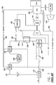
- product nitrogen (N 2 ) generated from the ASU is routed to the HRSG where it is heated by the gas turbine exhaust gas. After leaving this heat exchanger, the heated nitrogen gas product stream may be routed to another heat exchanger where it transfers heat to the syngas fuel. Upon leaving the heat exchanger, the nitrogen is then returned to the HRSG and heated in yet another heat exchanger. Upon exiting this heat exchanger, it is mixed with the fuel stream and then enters the combustor of the gas turbine.
- Figure 2 provides a schematic of this embodiment.
- the ASU 200 includes an oxygen gas product stream 205 that may be sent to the gasifier 210 for use in forming the syngas product stream 215.
- the nitrogen product gas stream 220 from the ASU 200 may then be passed through a heat exchanger 225 to heat the nitrogen gas 220.
- this embodiment diverts all or a part of the nitrogen gas stream 220 to a first nitrogen heater 235, which is located in the HRSG 255, wherein heat from the turbine 275 may be transferred to the nitrogen gas 220.
- the heated nitrogen flow may then be passed through a heat exchanger 280 to increase the temperature of the fuel mixture 240 entering the combustor 230.
- the nitrogen gas stream 220 may then be sent to a second nitrogen heater 285 within the HRSG 255 and then mixed with the heated syngas, such as with a mixing valve, to form the fuel mixture 240 that then enters the combustor 230.
- This embodiment may also include a syngas cooler 245, which uses feedwater 250 from the HRSG 255 to form steam 260 that may be used to generate power in the HRSG; an acid gas removal stage 265; and a syngas heater 270.
- Combustion products from the combustor 230 may be sent to gas turbine 275 to produce power, and since the temperature of the fuel mixture 240 is higher, the temperature of the combustion products is higher, thereby producing more power in the turbine.
- FIG. 2 shows all of the ASU product nitrogen gas being routed through the heat exchanger system; however, it is also possible that only a fraction of the product nitrogen may be routed in this manner.
- the heat exchanger 280 is depicted as downstream of the nitrogen fuel mixing point 282; however, this heat exchanger could also be upstream of the mixing point.
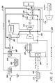
- product nitrogen (N 2 ) gas generated from the ASU is routed to the HRSG where it is heated by the gas turbine exhaust gas. After leaving this heat exchanger, the heated nitrogen is mixed with the fuel stream and then enters the combustor of the gas turbine.
- Figure 3 provides a schematic of this embodiment.
- the ASU 300 includes an oxygen gas product stream 305 that may be sent to the gasifier 310 for use in forming the syngas product stream 315.
- the nitrogen product gas stream 320 from the ASU 300 may then be passed through a heat exchanger 325 to heat the nitrogen gas 320.
- this embodiment diverts all or a part of the nitrogen gas stream 320 to be heated by the HRSG 355 using a nitrogen heat exchanger 335.
- the heated nitrogen stream may then be mixed with the syngas stream 315, such as through the use of a mixing valve, to form a fuel mixture 340 prior to being combusted in the combustor 330.
- This embodiment may also include a syngas cooler 345, which uses feedwater 350 from the HRSG 355 to form steam 360 that may be used to generate power in the HRSG; an acid gas removal stage 365; and a syngas heater 370. Combustion products from the combustor 330 may be sent to gas turbine 375 to produce power.
- Figure 3 shows all of the ASU nitrogen product gas 320 being routed through the heat exchanger 335; however, it is also possible that only a fraction of the product nitrogen could be routed in this manner.
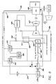
- product nitrogen generated from the ASU is routed to the HRSG where it is heated by the gas turbine exhaust gas. After leaving this heat exchanger, the heated nitrogen gas may be routed to an oxygen heat exchanger wherein heat is transferred to the ASU product oxygen stream prior to being used in the gasifier. The nitrogen stream may then be routed back to the HRSG where it is reheated before mixing with the fuel stream that enters the combustor of the gas turbine.
- Figure 4 provides a schematic of this embodiment.
- the ASU 400 includes an oxygen gas product stream 405 that may be sent to the gasifier 410 for use in forming the syngas product stream 415.
- the nitrogen product gas stream 420 from the ASU 400 may then be passed through a heat exchanger 425 to heat the nitrogen gas 420.
- this embodiment diverts all or a part of the nitrogen gas stream 420 to a first nitrogen heater 435, which is located in the HRSG 455, wherein heat from the turbine 475 may be transferred to the nitrogen gas 420.
- the heated nitrogen gas can then be passed through an oxygen gas heat exchanger 490 to increase the temperature of oxygen gas stream 405 entering the gasifier 410.
- the nitrogen gas stream 420 may then be sent to a second nitrogen heater 485 within the HRSG 455 and then mixed with the heated syngas to form the fuel mixture 440 that then enters the combustor 430.
- This embodiment may include a syngas cooler 445, which uses feedwater 450 from the HRSG 455 to form steam 460 that may be used to generate power in the HRSG 455; an acid gas removal stage 465; and a syngas heater 470.
- Combustion products from the combustor 430 may be sent to gas turbine 475 to produce power, and since the temperature of the fuel mixture 440 is higher, the temperature of the combustion products is higher, thereby producing more power in the turbine. And, since the temperature of the oxygen gas stream 405 is higher, greater amounts of syngas 415 may be generated in the gasifier 410.
- heat in the form of steam, may be transferred upstream, such as through the use of steam.
- flue gas energy may be used to generate high pressure superheated steam in the HRSG.
- This steam is routed to a heat exchanger where it transfers heat to one or more of the syngas, the diluent nitrogen, and/or the mixed fuel stream.
- the steam may then be sent from the heat exchangers and returned to the HRSG to be reheated.
- Figure 5 provides a schematic of this embodiment.
- the ASU 500 includes an oxygen gas product stream 505 that may be sent to the gasifier 510 for use in forming the syngas product stream 515.
- the nitrogen product gas stream 520 from the ASU 500 may be passed through a heat exchanger 525 to heat the nitrogen gas 520.
- a superheated steam stream 592 which is formed using heat from the HRSG 555, may be used to heat one or more of the syngas (using heat exchanger 594), the diluent nitrogen (using heat exchanger 596), and/or the mixed fuel stream (using heat exchanger 598).
- the resulting heated fuel mixture 540 then enters the combustor 530. Combustion products from the combustor 530 can be sent to the turbine 575 to produce power.
- Figure 5 shows the steam leaving the heat exchanger returning to the HRSG; however, it may be routed to the gasifier as a feedstock, to a water-gas shift reactor or syngas saturator as a feed stock, to the steam turbine as a working fluid, or elsewhere in the IGCC plant.
- the HRSG steam shown in Figure 5 may be a High Pressure (HP) steam; however, it is possible that steam of a lower pressure could be used for this heating application.
- HP High Pressure
- superheated steam generated in either the syngas cooler or HRSG heat exchangers, or a combination of both is routed to an oxygen heat exchanger where heat is transferred to the ASU product oxygen stream prior to being used in the gasifier.
- the liquid stream whether in form of saturated steam or condensed as water, may then be routed back to the HRSG.
- Figure 6 provides a schematic of one aspect of this embodiment.
- the ASU 600 includes an oxygen gas product stream 605 that may be sent to the gasifier 610 for use in forming the syngas product stream 615.
- the nitrogen product gas stream 620 from the ASU 600 may be passed through a heat exchanger 625 to heat the nitrogen gas 620.
- the heated nitrogen stream can be combined with the fuel 615 to form a fuel mixture 640 that is fed to the combustor 630.
- a superheated steam stream 692 which is formed using heat from the HRSG 655, may be passed through an oxygen gas heat exchanger 690 to increase the temperature of oxygen gas stream 605 entering the gasifier 610.
- This embodiment may include a syngas cooler 645, which uses feedwater 650 from the HRSG 655 to form steam 660 that may be used to generate power in the HRSG; an acid gas removal stage 665; and a syngas heater 670.
- the stream 660 may be used in lieu of steam stream 692 or in addition thereto.
- Combustion products from the combustor 630 can be directed to the turbine 675 to produce power.
Landscapes
- Engineering & Computer Science (AREA)
- Chemical & Material Sciences (AREA)
- Combustion & Propulsion (AREA)
- Mechanical Engineering (AREA)
- General Engineering & Computer Science (AREA)
- Physics & Mathematics (AREA)
- Thermal Sciences (AREA)
- Power Engineering (AREA)
- Engine Equipment That Uses Special Cycles (AREA)
Applications Claiming Priority (2)
| Application Number | Priority Date | Filing Date | Title |
|---|---|---|---|
| US11/350,568 US8075646B2 (en) | 2006-02-09 | 2006-02-09 | Advanced ASU and HRSG integration for improved integrated gasification combined cycle efficiency |
| EP07748958.1A EP1982053B1 (de) | 2006-02-09 | 2007-01-18 | Verfahren zur erhöhung der effizienz eines integrierten gasifizierungs-kombinationskreislaufs |
Related Parent Applications (2)
| Application Number | Title | Priority Date | Filing Date |
|---|---|---|---|
| EP07748958.1A Division-Into EP1982053B1 (de) | 2006-02-09 | 2007-01-18 | Verfahren zur erhöhung der effizienz eines integrierten gasifizierungs-kombinationskreislaufs |
| EP07748958.1 Division | 2007-01-18 |
Publications (1)
| Publication Number | Publication Date |
|---|---|
| EP2535532A1 true EP2535532A1 (de) | 2012-12-19 |
Family
ID=38191130
Family Applications (2)
| Application Number | Title | Priority Date | Filing Date |
|---|---|---|---|
| EP12182946A Withdrawn EP2535532A1 (de) | 2006-02-09 | 2007-01-18 | Erweiterte ASU- und HRSG-Integration für eine verbesserte Wirksamkeit des integrierten Gasifizierungs-Kombinationskreislaufs |
| EP07748958.1A Not-in-force EP1982053B1 (de) | 2006-02-09 | 2007-01-18 | Verfahren zur erhöhung der effizienz eines integrierten gasifizierungs-kombinationskreislaufs |
Family Applications After (1)
| Application Number | Title | Priority Date | Filing Date |
|---|---|---|---|
| EP07748958.1A Not-in-force EP1982053B1 (de) | 2006-02-09 | 2007-01-18 | Verfahren zur erhöhung der effizienz eines integrierten gasifizierungs-kombinationskreislaufs |
Country Status (3)
| Country | Link |
|---|---|
| US (2) | US8075646B2 (de) |
| EP (2) | EP2535532A1 (de) |
| WO (1) | WO2007094914A1 (de) |
Families Citing this family (42)
| Publication number | Priority date | Publication date | Assignee | Title |
|---|---|---|---|---|
| US8133298B2 (en) * | 2007-12-06 | 2012-03-13 | Air Products And Chemicals, Inc. | Blast furnace iron production with integrated power generation |
| US8015793B2 (en) * | 2008-07-18 | 2011-09-13 | Siemens Energy, Inc. | Fuel heating via exhaust gas extraction |
| US9328631B2 (en) * | 2009-02-20 | 2016-05-03 | General Electric Company | Self-generated power integration for gasification |
| US9416728B2 (en) | 2009-02-26 | 2016-08-16 | 8 Rivers Capital, Llc | Apparatus and method for combusting a fuel at high pressure and high temperature, and associated system and device |
| US8596075B2 (en) * | 2009-02-26 | 2013-12-03 | Palmer Labs, Llc | System and method for high efficiency power generation using a carbon dioxide circulating working fluid |
| US10018115B2 (en) | 2009-02-26 | 2018-07-10 | 8 Rivers Capital, Llc | System and method for high efficiency power generation using a carbon dioxide circulating working fluid |
| US8418472B2 (en) | 2009-05-22 | 2013-04-16 | General Electric Company | Method and system for use with an integrated gasification combined cycle plant |
| EP2292554A1 (de) | 2009-09-02 | 2011-03-09 | Ammonia Casale S.A. | Herstellung von Ammoniak-Zusatz-Syngas mit kyrogener Reinigung |
| US8529679B2 (en) * | 2009-11-05 | 2013-09-10 | General Electric Company | System and method for improving performance of an IGCC power plant |
| CN102892480B (zh) | 2010-05-24 | 2015-09-09 | 气体产品与化学公司 | 用于合成气处理的方法和系统 |
| US20120067054A1 (en) | 2010-09-21 | 2012-03-22 | Palmer Labs, Llc | High efficiency power production methods, assemblies, and systems |
| US9410481B2 (en) | 2010-09-21 | 2016-08-09 | 8 Rivers Capital, Llc | System and method for high efficiency power generation using a nitrogen gas working fluid |
| US8869889B2 (en) | 2010-09-21 | 2014-10-28 | Palmer Labs, Llc | Method of using carbon dioxide in recovery of formation deposits |
| KR102044831B1 (ko) | 2011-11-02 | 2019-11-15 | 8 리버스 캐피탈, 엘엘씨 | 전력 생산 시스템 및 상응하는 방법 |
| JP5642657B2 (ja) * | 2011-12-06 | 2014-12-17 | 三菱重工業株式会社 | 燃料ガス化システム、その制御方法及び制御プログラム、並びに、燃料ガス化システムを備える燃料ガス化複合発電システム |
| US8776532B2 (en) | 2012-02-11 | 2014-07-15 | Palmer Labs, Llc | Partial oxidation reaction with closed cycle quench |
| US9322295B2 (en) * | 2012-10-17 | 2016-04-26 | General Electric Company | Thermal energy storage unit with steam and gas turbine system |
| US9163827B2 (en) * | 2012-11-01 | 2015-10-20 | General Electric Company | System and method for using boiler feedwater |
| US20140130509A1 (en) * | 2012-11-13 | 2014-05-15 | Raymond Francis Drnevich | Combined gasification and power generation |
| US9376962B2 (en) | 2012-12-14 | 2016-06-28 | General Electric Company | Fuel gas heating with thermal energy storage |
| JP5960077B2 (ja) * | 2013-02-20 | 2016-08-02 | 三菱日立パワーシステムズ株式会社 | ボイラ運転方法およびボイラ |
| CN103388497B (zh) * | 2013-08-09 | 2015-05-20 | 中国能源建设集团广东省电力设计研究院 | 用于改进igcc发电设施性能的预热清洁合成气方法及系统 |
| JP6250332B2 (ja) | 2013-08-27 | 2017-12-20 | 8 リバーズ キャピタル,エルエルシー | ガスタービン設備 |
| TWI691644B (zh) | 2014-07-08 | 2020-04-21 | 美商八河資本有限公司 | 具改良效率之功率生產方法及系統 |
| WO2016040108A1 (en) | 2014-09-09 | 2016-03-17 | 8 Rivers Capital, Llc | Production of low pressure liquid carbon dioxide from a power production system and method |
| US11231224B2 (en) | 2014-09-09 | 2022-01-25 | 8 Rivers Capital, Llc | Production of low pressure liquid carbon dioxide from a power production system and method |
| CN104373164B (zh) * | 2014-11-05 | 2015-10-21 | 中国华能集团清洁能源技术研究院有限公司 | 一种带补燃型余热锅炉的igcc电站系统及工作方法 |
| US11686258B2 (en) | 2014-11-12 | 2023-06-27 | 8 Rivers Capital, Llc | Control systems and methods suitable for use with power production systems and methods |
| MA40950A (fr) | 2014-11-12 | 2017-09-19 | 8 Rivers Capital Llc | Systèmes et procédés de commande appropriés pour une utilisation avec des systèmes et des procédés de production d'énergie |
| US10961920B2 (en) | 2018-10-02 | 2021-03-30 | 8 Rivers Capital, Llc | Control systems and methods suitable for use with power production systems and methods |
| MX2017016478A (es) | 2015-06-15 | 2018-05-17 | 8 Rivers Capital Llc | Sistema y metodo para la puesta en marcha de una instalacion de produccion de energia. |
| WO2017141186A1 (en) | 2016-02-18 | 2017-08-24 | 8 Rivers Capital, Llc | System and method for power production including methanation |
| JP7001608B2 (ja) | 2016-02-26 | 2022-01-19 | 8 リバーズ キャピタル,エルエルシー | 電力プラントを制御するためのシステムおよび方法 |
| EP3512925B1 (de) | 2016-09-13 | 2022-03-30 | 8 Rivers Capital, LLC | System und verfahren zur energieerzeugung mit partieller oxidation |
| CN111094720B (zh) | 2017-08-28 | 2023-02-03 | 八河流资产有限责任公司 | 回热式超临界co2动力循环的低等级热优化 |
| PL3759322T3 (pl) | 2018-03-02 | 2024-03-18 | 8 Rivers Capital, Llc | Układy i sposoby wytwarzania energii z wykorzystaniem płynu roboczego z dwutlenku węgla |
| US11549432B2 (en) * | 2018-09-21 | 2023-01-10 | King Fahd University Of Petroleum And Minerals | Integrated chemical looping combustion system and method for power generation and carbon dioxide capture |
| US11149636B2 (en) | 2019-03-01 | 2021-10-19 | Richard Alan Callahan | Turbine powered electricity generation |
| US11149634B2 (en) | 2019-03-01 | 2021-10-19 | Richard Alan Callahan | Turbine powered electricity generation |
| US11994063B2 (en) | 2019-10-16 | 2024-05-28 | Richard Alan Callahan | Turbine powered electricity generation |
| CN114901925A (zh) | 2019-10-22 | 2022-08-12 | 八河流资产有限责任公司 | 用于发电系统的热管理的控制方案和方法 |
| US11808206B2 (en) | 2022-02-24 | 2023-11-07 | Richard Alan Callahan | Tail gas recycle combined cycle power plant |
Citations (4)
| Publication number | Priority date | Publication date | Assignee | Title |
|---|---|---|---|---|
| GB2075124A (en) * | 1980-05-05 | 1981-11-11 | Gen Electric | Integrated gasification-methanol synthesis-combined cycle plant |
| JPS5783636A (en) * | 1980-11-14 | 1982-05-25 | Hitachi Ltd | Coal-gasifying power generation plant |
| US4976101A (en) * | 1985-09-02 | 1990-12-11 | Siemens Aktiengesellschaft | Combined gas and steam turbine power generating station |
| US5865023A (en) * | 1994-06-14 | 1999-02-02 | Air Products And Chemicals, Inc. | Gasification combined cycle power generation process with heat-integrated chemical production |
Family Cites Families (18)
| Publication number | Priority date | Publication date | Assignee | Title |
|---|---|---|---|---|
| US4806136A (en) * | 1987-12-15 | 1989-02-21 | Union Carbide Corporation | Air separation method with integrated gas turbine |
| GB8824216D0 (en) * | 1988-10-15 | 1988-11-23 | Boc Group Plc | Air separation |
| US5224336A (en) * | 1991-06-20 | 1993-07-06 | Air Products And Chemicals, Inc. | Process and system for controlling a cryogenic air separation unit during rapid changes in production |
| US5722259A (en) * | 1996-03-13 | 1998-03-03 | Air Products And Chemicals, Inc. | Combustion turbine and elevated pressure air separation system with argon recovery |
| US6669744B2 (en) | 1998-04-14 | 2003-12-30 | Air Products And Chemicals, Inc. | Process and apparatus for the production of synthesis gas |
| US5979183A (en) * | 1998-05-22 | 1999-11-09 | Air Products And Chemicals, Inc. | High availability gas turbine drive for an air separation unit |
| US6173563B1 (en) * | 1998-07-13 | 2001-01-16 | General Electric Company | Modified bottoming cycle for cooling inlet air to a gas turbine combined cycle plant |
| US6230480B1 (en) * | 1998-08-31 | 2001-05-15 | Rollins, Iii William Scott | High power density combined cycle power plant |
| US6220013B1 (en) * | 1999-09-13 | 2001-04-24 | General Electric Co. | Multi-pressure reheat combined cycle with multiple reheaters |
| DE10002084C2 (de) * | 2000-01-19 | 2001-11-08 | Siemens Ag | Gas- und Dampfturbinenanlage |
| US6397575B2 (en) * | 2000-03-23 | 2002-06-04 | General Electric Company | Apparatus and methods of reheating gas turbine cooling steam and high pressure steam turbine exhaust in a combined cycle power generating system |
| US20030181314A1 (en) * | 2001-08-31 | 2003-09-25 | Texaco Inc. | Using shifted syngas to regenerate SCR type catalyst |
| US7004985B2 (en) * | 2001-09-05 | 2006-02-28 | Texaco, Inc. | Recycle of hydrogen from hydroprocessing purge gas |
| US6588212B1 (en) * | 2001-09-05 | 2003-07-08 | Texaco Inc. | Combustion turbine fuel inlet temperature management for maximum power outlet |
| US6596780B2 (en) * | 2001-10-23 | 2003-07-22 | Texaco Inc. | Making fischer-tropsch liquids and power |
| US6871502B2 (en) * | 2002-02-15 | 2005-03-29 | America Air Liquide, Inc. | Optimized power generation system comprising an oxygen-fired combustor integrated with an air separation unit |
| US20030182944A1 (en) * | 2002-04-02 | 2003-10-02 | Hoffman John S. | Highly supercharged gas-turbine generating system |
| AU2003260832A1 (en) * | 2002-09-17 | 2004-04-08 | Foster Wheeler Energy Corporation | Advanced hybrid coal gasification cycle utilizing a recycled working fluid |
-
2006
- 2006-02-09 US US11/350,568 patent/US8075646B2/en not_active Expired - Fee Related
-
2007
- 2007-01-18 EP EP12182946A patent/EP2535532A1/de not_active Withdrawn
- 2007-01-18 EP EP07748958.1A patent/EP1982053B1/de not_active Not-in-force
- 2007-01-18 WO PCT/US2007/001297 patent/WO2007094914A1/en not_active Ceased
-
2011
- 2011-12-13 US US13/324,409 patent/US8715379B2/en not_active Expired - Fee Related
Patent Citations (4)
| Publication number | Priority date | Publication date | Assignee | Title |
|---|---|---|---|---|
| GB2075124A (en) * | 1980-05-05 | 1981-11-11 | Gen Electric | Integrated gasification-methanol synthesis-combined cycle plant |
| JPS5783636A (en) * | 1980-11-14 | 1982-05-25 | Hitachi Ltd | Coal-gasifying power generation plant |
| US4976101A (en) * | 1985-09-02 | 1990-12-11 | Siemens Aktiengesellschaft | Combined gas and steam turbine power generating station |
| US5865023A (en) * | 1994-06-14 | 1999-02-02 | Air Products And Chemicals, Inc. | Gasification combined cycle power generation process with heat-integrated chemical production |
Also Published As
| Publication number | Publication date |
|---|---|
| US8075646B2 (en) | 2011-12-13 |
| US20070180768A1 (en) | 2007-08-09 |
| EP1982053A1 (de) | 2008-10-22 |
| EP1982053B1 (de) | 2014-01-15 |
| US8715379B2 (en) | 2014-05-06 |
| WO2007094914A1 (en) | 2007-08-23 |
| US20120079766A1 (en) | 2012-04-05 |
Similar Documents
| Publication | Publication Date | Title |
|---|---|---|
| US8715379B2 (en) | Advanced ASU and HRSG integration for improved integrated gasification combined cycle efficiency | |
| EP1982052B1 (de) | Kombinierter gas- und dampfturbinen-prozess mit integrierter kohlevergasung und vorheizung von stickstoff bzw. sauerstoff aus einer luftzerlegungsanlage | |
| US8354082B2 (en) | System for heat integration with methanation system | |
| CZ188993A3 (en) | Process and apparatus for producing pure energy | |
| JP2008144136A (ja) | 非混合式燃料プロセッサを使用するシステムおよび方法 | |
| CA2715493C (en) | Methods and systems for integrated boiler feed water heating | |
| WO2006060883A1 (en) | Process and installation for producing electric power | |
| Andersen et al. | Gas turbine combined cycle with CO2-capture using auto-thermal reforming of natural gas | |
| TW384350B (en) | System and process for increasing the efficiency of a power generating unit | |
| US20100024432A1 (en) | Method for improved efficiency for IGCC | |
| US8713907B2 (en) | System for providing air flow to a sulfur recovery unit | |
| CN109181776A (zh) | 一种集成燃料电池发电的煤基多联产系统及方法 | |
| CN102234547B (zh) | 用于整合气化组合循环动力系统的水煤气变换反应器系统 | |
| Lozza et al. | Combined-cycle power stations using “Clean-coal technologies”: Thermodynamic analysis of full gasification versus fluidized bed combustion with partial gasification | |
| US20120216501A1 (en) | Chemical reactor featuring heat extraction | |
| WO2009034285A2 (en) | Improved power plant | |
| O’Keefe et al. | A single IGCC design for variable CO2 capture | |
| Cau et al. | Performance of zero emissions integrated gasification hydrogen combustion (ZE-IGHC) power plants with CO2 removal | |
| Kreutz et al. | Shell gasifier-based coal IGCC with CO2 capture: partial water quench vs. novel water-gas shift | |
| KR20250164819A (ko) | 메탄 열분해 기반 가스 터빈 시스템 및 방법 | |
| WO2023167922A1 (en) | Electric power co-generation for chemical and physical processes with steam utilization | |
| Fiaschi et al. | The R-ATR and the R-REF Gas Turbine Power Cycles With CO2 Removal: Part 2—The R-REF Cycle |
Legal Events
| Date | Code | Title | Description |
|---|---|---|---|
| PUAI | Public reference made under article 153(3) epc to a published international application that has entered the european phase |
Free format text: ORIGINAL CODE: 0009012 |
|
| AC | Divisional application: reference to earlier application |
Ref document number: 1982053 Country of ref document: EP Kind code of ref document: P |
|
| AK | Designated contracting states |
Kind code of ref document: A1 Designated state(s): AT BE BG CH CY CZ DE DK EE ES FI FR GB GR HU IE IS IT LI LT LU LV MC NL PL PT RO SE SI SK TR |
|
| 17P | Request for examination filed |
Effective date: 20130618 |
|
| RBV | Designated contracting states (corrected) |
Designated state(s): AT BE BG CH CY CZ DE DK EE ES FI FR GB GR HU IE IS IT LI LT LU LV MC NL PL PT RO SE SI SK TR |
|
| STAA | Information on the status of an ep patent application or granted ep patent |
Free format text: STATUS: REQUEST FOR EXAMINATION WAS MADE |
|
| STAA | Information on the status of an ep patent application or granted ep patent |
Free format text: STATUS: THE APPLICATION IS DEEMED TO BE WITHDRAWN |
|
| 18D | Application deemed to be withdrawn |
Effective date: 20170801 |