EP2535534B1 - Schalldämpfer für einen verbrennungsmotor - Google Patents
Schalldämpfer für einen verbrennungsmotor Download PDFInfo
- Publication number
- EP2535534B1 EP2535534B1 EP11737216.9A EP11737216A EP2535534B1 EP 2535534 B1 EP2535534 B1 EP 2535534B1 EP 11737216 A EP11737216 A EP 11737216A EP 2535534 B1 EP2535534 B1 EP 2535534B1
- Authority
- EP
- European Patent Office
- Prior art keywords
- outlet pipe
- muffler
- outer shell
- internal combustion
- combustion engine
- Prior art date
- Legal status (The legal status is an assumption and is not a legal conclusion. Google has not performed a legal analysis and makes no representation as to the accuracy of the status listed.)
- Active
Links
Images



Classifications
-
- F—MECHANICAL ENGINEERING; LIGHTING; HEATING; WEAPONS; BLASTING
- F01—MACHINES OR ENGINES IN GENERAL; ENGINE PLANTS IN GENERAL; STEAM ENGINES
- F01N—GAS-FLOW SILENCERS OR EXHAUST APPARATUS FOR MACHINES OR ENGINES IN GENERAL; GAS-FLOW SILENCERS OR EXHAUST APPARATUS FOR INTERNAL-COMBUSTION ENGINES
- F01N1/00—Silencing apparatus characterised by method of silencing
- F01N1/08—Silencing apparatus characterised by method of silencing by reducing exhaust energy by throttling or whirling
- F01N1/083—Silencing apparatus characterised by method of silencing by reducing exhaust energy by throttling or whirling using transversal baffles defining a tortuous path for the exhaust gases or successively throttling exhaust gas flow
-
- F—MECHANICAL ENGINEERING; LIGHTING; HEATING; WEAPONS; BLASTING
- F01—MACHINES OR ENGINES IN GENERAL; ENGINE PLANTS IN GENERAL; STEAM ENGINES
- F01N—GAS-FLOW SILENCERS OR EXHAUST APPARATUS FOR MACHINES OR ENGINES IN GENERAL; GAS-FLOW SILENCERS OR EXHAUST APPARATUS FOR INTERNAL-COMBUSTION ENGINES
- F01N1/00—Silencing apparatus characterised by method of silencing
- F01N1/08—Silencing apparatus characterised by method of silencing by reducing exhaust energy by throttling or whirling
- F01N1/081—Silencing apparatus characterised by method of silencing by reducing exhaust energy by throttling or whirling by passing the exhaust gases through a mass of particles
-
- F—MECHANICAL ENGINEERING; LIGHTING; HEATING; WEAPONS; BLASTING
- F01—MACHINES OR ENGINES IN GENERAL; ENGINE PLANTS IN GENERAL; STEAM ENGINES
- F01N—GAS-FLOW SILENCERS OR EXHAUST APPARATUS FOR MACHINES OR ENGINES IN GENERAL; GAS-FLOW SILENCERS OR EXHAUST APPARATUS FOR INTERNAL-COMBUSTION ENGINES
- F01N1/00—Silencing apparatus characterised by method of silencing
- F01N1/08—Silencing apparatus characterised by method of silencing by reducing exhaust energy by throttling or whirling
- F01N1/084—Silencing apparatus characterised by method of silencing by reducing exhaust energy by throttling or whirling the exhaust gases flowing through the silencer two or more times longitudinally in opposite directions, e.g. using parallel or concentric tubes
-
- F—MECHANICAL ENGINEERING; LIGHTING; HEATING; WEAPONS; BLASTING
- F01—MACHINES OR ENGINES IN GENERAL; ENGINE PLANTS IN GENERAL; STEAM ENGINES
- F01N—GAS-FLOW SILENCERS OR EXHAUST APPARATUS FOR MACHINES OR ENGINES IN GENERAL; GAS-FLOW SILENCERS OR EXHAUST APPARATUS FOR INTERNAL-COMBUSTION ENGINES
- F01N1/00—Silencing apparatus characterised by method of silencing
- F01N1/08—Silencing apparatus characterised by method of silencing by reducing exhaust energy by throttling or whirling
- F01N1/085—Silencing apparatus characterised by method of silencing by reducing exhaust energy by throttling or whirling throttling exhaust gas flow using a central core in a flow passage
-
- F—MECHANICAL ENGINEERING; LIGHTING; HEATING; WEAPONS; BLASTING
- F01—MACHINES OR ENGINES IN GENERAL; ENGINE PLANTS IN GENERAL; STEAM ENGINES
- F01N—GAS-FLOW SILENCERS OR EXHAUST APPARATUS FOR MACHINES OR ENGINES IN GENERAL; GAS-FLOW SILENCERS OR EXHAUST APPARATUS FOR INTERNAL-COMBUSTION ENGINES
- F01N1/00—Silencing apparatus characterised by method of silencing
- F01N1/08—Silencing apparatus characterised by method of silencing by reducing exhaust energy by throttling or whirling
- F01N1/086—Silencing apparatus characterised by method of silencing by reducing exhaust energy by throttling or whirling having means to impart a whirling motion to the exhaust gases
-
- F—MECHANICAL ENGINEERING; LIGHTING; HEATING; WEAPONS; BLASTING
- F01—MACHINES OR ENGINES IN GENERAL; ENGINE PLANTS IN GENERAL; STEAM ENGINES
- F01N—GAS-FLOW SILENCERS OR EXHAUST APPARATUS FOR MACHINES OR ENGINES IN GENERAL; GAS-FLOW SILENCERS OR EXHAUST APPARATUS FOR INTERNAL-COMBUSTION ENGINES
- F01N2470/00—Structure or shape of exhaust gas passages, pipes or tubes
- F01N2470/02—Tubes being perforated
-
- F—MECHANICAL ENGINEERING; LIGHTING; HEATING; WEAPONS; BLASTING
- F01—MACHINES OR ENGINES IN GENERAL; ENGINE PLANTS IN GENERAL; STEAM ENGINES
- F01N—GAS-FLOW SILENCERS OR EXHAUST APPARATUS FOR MACHINES OR ENGINES IN GENERAL; GAS-FLOW SILENCERS OR EXHAUST APPARATUS FOR INTERNAL-COMBUSTION ENGINES
- F01N2470/00—Structure or shape of exhaust gas passages, pipes or tubes
- F01N2470/30—Tubes with restrictions, i.e. venturi or the like, e.g. for sucking air or measuring mass flow
Definitions
- the present invention relates to a muffler for an internal combustion engine, which is provided in an exhaust-gas flow path in the internal combustion engine to reduce exhaust noise.
- Patent Document 1 in an exhaust-gas flow path of an internal combustion engine, an exhaust manifold, a catalytic converter, a sub muffler, a main muffler, and a tail pipe are disposed in the exhaust-gas flow path and installed in a space under a floor of a vehicle.
- Exhaust noise generally includes explosion noise inside a cylinder(s) of an internal combustion engine, gas-flow noise generated by a flow of exhaust gases, a standing wave generated by air-column resonance due to lengths of exhaust pipes, and so on.
- silencing performance with respect to a low-frequency noise may be deteriorated because of an influence of the standing wave generated within each of these exhaust pipes.
- the low-frequency noise causes a muffled sound inside a vehicle, and this muffled sound is a factor of giving an uncomfortable feeling to a passenger in the vehicle.
- a main muffler with a large capacity or a sub muffler is used.
- a resonant frequency is increased to a frequency which does not pose a problem by increasing the capacity of the main muffler 100 or disposing a sub muffler 104 somewhere within the length of the exhaust pipe 102 to shorten an actual length of the exhaust pipe 102, as shown in FIG. 4B .
- FIG. 4C shows a relationship between a number of rotation of an internal combustion engine and sound pressure level, in a case where a sub muffler is not disposed.
- a vertical axis shows the sound pressure level
- a horizontal axis shows the number of rotation of the internal combustion engine.
- Patent Document 1 Japanese Unexamined Patent Application Publication No. 2001-221043
- DE 4032185 (A1 ) discloses an Absorption silencer for IC engine which has series of intermediate ducts heated by exhaust gas.
- a two-part casing contains at least four chambers separated by plates.
- An exhaust inlet passes through the end plate and each of the chambers.
- the two outer chambers are linked by a corrugated plate fitted to the inside of half the casing and forming a series of parallel intermediated ducts.
- An exhaust gas outlet passes from the end chamber through to the plate at the other end. All chambers except the end ones are packed with rock wool and either the inlet or outlet pipe is perforated where it passes throug each of the packed chambers.
- the Absorbtion-type silencer for IC engine has casing which keeps the insulation dry; efficiency does not deteriorate, silencer lasts longer.
- An object of the present invention is to provide a muffler for an internal combustion engine, with which the weight increase and the influence on the layout can be suppressed.
- a muffler for an internal combustion engine according to claim 1 is provided.
- the at least one constricted part makes it possible to inhibit a sound reflection from reflecting in an uniform direction. Consequently, the muffler for an internal combustion engine of the present invention exhibits the following effects: it is possible to reduce generation of the standing wave, reduce exhaust noise without introducing a large capacity and weight increase, and to reduce increase of the weight as well as influence on the layout.
- the muffler for an internal combustion engine provided with the tapered part it is possible to inhibit a sound reflection from reflecting in an uniform direction with respect to a wider range, in the at least one of the inlet pipe and the outlet pipe. Consequently, exhaust noise can be reduced in the tapered part as well, without introducing a large capacity and weight increase.
- an area where a constricted part is to be formed can be localized; thus, pressure loss (inlet loss) in the constricted part can be minimized.
- exhaust noise can be reduced by the small bore as well without introducing a large capacity and weight increase.
- a muffler 70 for an internal combustion engine is provided with an outer shell 1, an inlet pipe 16, and an outlet pipe 22.
- the outer shell 1 includes a cylindrical tube part 2, and sidewall parts 4 and 6.
- the sidewall parts 4 and 6 close both ends of the tube part 2.
- the outer shell 1 is formed to have a hollow thereinside.
- partition walls 8 and 10 are provided inside the hollow of the outer shell 1.
- the tube part 2 is divided by the partition walls 8 and 10 into a plurality of a first expansion chamber 12 to a third expansion chamber 14.
- the inlet pipe 16 penetrates through the sidewall part 4 at one side of the outer shell 1 and is inserted into the hollow.
- the inlet pipe 16 penetrates through the partition walls 8 and 10 to pass through inside the third expansion chamber 14 and the second expansion chamber 13; consequently, one end of the inlet pipe 16 is located within the first expansion chamber 12.
- This one end of the inlet pipe 16, which is located within the first expansion chamber 12 has an opening.
- Multiple through holes 18 are bored in a part, which is located within the second expansion chamber 13, of an outer circumference of the inlet pipe 16. Also, multiple though holes 20 are bored in a part, which is located within the first expansion chamber 12, of the outer circumference of the inlet pipe 16. The other end of the inlet pipe 16 is connected to a not-shown upstream exhaust pipe, so as to introduce exhaust gases from an internal combustion engine 60 into the inlet pipe 16.
- the outlet pipe 22 penetrates through the sidewall part 6 at the other side of the outer shell 1 and is inserted into the hollow.
- the outlet pipe 22 penetrates through the partition walls 8 and 10 to pass through the first expansion chamber 12 and the second expansion chamber 13; consequently, one end of the outlet pipe 22 is located within the third expansion chamber 14.
- This one end, which is located within the third expansion chamber 14, of the outlet pipe 22 (hereinafter, referred to as upstream end) has an opening.
- the other end of the outlet pipe 14 (hereinafter, referred to as downstream end) is connected to a not-shown downstream exhaust pipe, so as to discharge the exhaust gases from the internal combustion engine 60.
- constricted part 24 In the upstream end of the outlet pipe 22, a constricted part 24 is formed.
- the constricted part 24 has a cross-sectional area smaller than cross-sectional areas in other parts of the outlet pipe 22.
- the cross-sectional area of the constricted part 24 may be determined in an appropriate manner by experiments, etc., depending on silencing performance.
- the outlet pipe 22 includes a tapered part 26 which has a diameter decreasing from the downstream end toward the constricted part 24.
- the tapered part 26 is provided within the outer shell 1.
- the tapered part 26 in the present example is formed to have a length from the constricted part 24 to a vicinity of the sidewall part 6 at the other side (i.e., the downstream end).
- the outlet pipe 22 also includes a straight part 27 provided to connect with the tapered part 26.
- the downstream exhaust pipe is connected to the straight part 27.
- the downstream exhaust pipe may be connected to the tapered part 26 without the straight part 27.
- a flared part 28 is formed from the constricted part 24 on a side opposite from a side where the tapered part 26 is provided.
- the flared part 28 is formed in a tapered manner such that a diameter of the flared part 28 gradually increases from the constricted part 24.
- An end of the flared part 28 has an opening within the third expansion chamber 14.
- small bores 30 are formed on a side where the sidewall part 6 is provided.
- the small bores 30 are formed in the straight part 27 and are provided so as to open within the first expansion chamber 12.
- a standing wave is generated in the outlet pipe 22 and in a downstream-side connection pipe connected to the outlet pipe 22, depending on a wavelength of sound generated at the aforementioned number of rotation and also on lengths of the outlet pipe 22 and of the downstream-side connection pipe connected to the outlet pipe 22.
- nodes are formed in the constricted part 24.
- the standing wave there exists multiple components such as a primary component, a secondary component, etc., depending on the number of rotation per unit time of the internal combustion engine 60 (here, a lowest frequency at which a standing wave is generated is the primary component).
- the small bores 30 are preferably configured to have an opening area which is equal to or less than one-fifth of a cross-sectional area of the outlet pipe 22.
- a total opening area of the plurality of small bores 30 is preferably equal to or less than one-fifth of the cross-sectional area of the outlet pipe 22.
- the exhaust gases which have flown into the second expansion chamber 13 flow into the third expansion chamber 14 via the not-shown holes in the partition wall 8, and then flow into the flared part 28 of the outlet pipe 22 from the third expansion chamber 14.
- the exhaust gases flow from the flared part 28 through the constricted part 24, and pass through the tapered part 26. Then, the exhaust gases are discharged from the outlet pipe 22 to the downstream exhaust pipe.
- a standing wave is generated in the outlet pipe and also in the downstream exhaust pipe.
- the standing wave is generated as a result of synthesizing two waves: a wave generated due to flowing of the exhaust gases inside the outlet pipe and the downstream exhaust pipe (hereinafter, referred to as exhaust wave), and a reflection wave which is the exhaust wave reflecting along an axial direction of the outlet pipe and the downstream exhaust pipe.
- the muffler 70 for the internal combustion engine when the constricted part 24 and the tapered part 26 are provided, an end part of the outlet pipe 22 is made to be narrowed. Therefore, the exhaust wave reflecting along the axial direction of the outlet pipe 22 and the downstream exhaust pipe is reduced. Consequently, the muffler 70 for the internal combustion engine can inhibit generation of the reflection wave which is a factor of generation of a resonance phenomenon; therefore, the muffler 70 for the internal combustion engine can also reduce a sound pressure of a sound generated due to the flowing of the exhaust gases inside the outlet pipe 22 and the downstream exhaust pipe.
- the muffler for an internal combustion engine of the present example can be implemented, without forming the tapered part 26, by providing a cap on an open side of the straight-shaped outlet pipe 22 and forming a hole in the cap, thereby constituting the constricted part 24.
- the constricted part 24 is formed in a localized manner, thereby making it possible to minimize increase of pressure loss.
- the tapered part 26 since the tapered part 26 is provided to connect with the constricted part 24 in the outlet pipe 22, the tapered part 26 inhibits generation of the reflection wave which increases a pressure loss and which causes generation of a resonance phenomenon, thereby reducing a sound pressure of the standing wave. If the length of the tapered part 26 is long, an effect of the aforementioned reduction is greater; it is preferable that the length of the tapered part 26 is about one-fourth of a wavelength of a primary component.
- the small bores 30 formed in the outer circumference of the outlet pipe 22 make it possible to reduce a phenomenon of air-column resonance caused by the standing wave. That is, when the internal combustion engine 60 is decelerated, exhaust gases flow out to the first expansion chamber 12 via the small bores 30, thereby reducing the sound pressure of the standing wave. When the internal combustion engine 60 is accelerated, exhaust gases flow into the outlet pipe 22 via the small bores 30 from the first expansion chamber 12, thereby inhibiting generation of the reflection wave. Moreover, the small bores 30 have an effect of inhibiting increase of a pressure loss, which is caused by the constricted part 24, at the time of acceleration.
- the flared part 28 inhibits occurrence of a turbulent flow of the exhaust gases flowing into the outlet pipe 22 from the third expansion chamber 14. Also, the flared part 28 reduces increase of a pressure loss in the exhaust gases flowing into the outlet pipe 22, especially, a pressure loss when a flow amount of the exhaust gases is increased at the time of acceleration, etc.
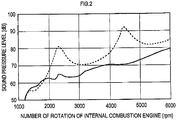
- a solid line shows, in the muffler 70 for the internal combustion engine of the present example, a relationship between a number of rotation of the internal combustion engine and sound pressure level.
- a broken line in FIG. 2 shows a relationship between a number of rotation of an internal combustion engine and sound pressure level, in a conventional muffler in which the flared part 28, the constricted part 24, and the tapered part 26 are not provided.
- the muffler 70 for the internal combustion engine of the present example can reduce the sound pressure level at a number of rotation of the internal combustion engine, which corresponds to the primary component and the secondary component.
- the muffler for the internal combustion engine of the present invention is implemented without the flared part 28, as shown in FIG. 3A .
- the muffler for the internal combustion engine may be provided with, in an embodiment not being part of the present invention and as shown in FIG. 3B , a constricted part 32 and a tapered part 34 in the inlet pipe 16.
- the constricted part 32 may be provided at an open side of the inlet pipe 16, opening toward an inside of the outer shell 1.
- the tapered part 34 may be formed to have a diameter decreasing from an end, which is to be connected to the internal combustion engine 60, of the inlet pipe 16 toward the constricted part 32.
- both of the inlet pipe 16 and the outlet pipe 22 may be provided, respectively, with the constricted parts 24 and 32 and the tapered parts 26 and 34.
- the present invention is not limited to this embodiment, but can be configured as a muffler for an internal combustion engine, which is provided with a resonant chamber.
- the outer shell 1 is divided by the partition walls 8 and 36, thereby forming a resonant chamber 38.
- the outlet pipe 22 is disposed in such a manner to penetrate through the resonant chamber 38.
- the small bores 30 are to be formed outside the resonant chamber 38.
Landscapes
- Engineering & Computer Science (AREA)
- Chemical & Material Sciences (AREA)
- Combustion & Propulsion (AREA)
- Mechanical Engineering (AREA)
- General Engineering & Computer Science (AREA)
- Exhaust Silencers (AREA)
Claims (5)
- Schalldämpfer (70) für einen Verbrennungsmotor (60), umfassend:eine Außenhülle (1) mit mindestens einer Trennwand (8, 10), die einen Innenraum der Außenhülle (1) in mindestens zwei Kammern (12, 13, 14) unterteilt;ein Einlassrohr (16), das in der Außenhülle (1) eingeschlossen ist und in das die von dem Verbrennungsmotor (60) abgegebenen Abgase eingeführt werden;ein Auslassrohr (22), das in der Außenhülle (1) eingeschlossen ist und das die Abgase abgibt;einen verengten Teil (24), der an einer offenen Seite des Auslassrohrs (22) vorgesehen ist und sich zu einer Innenseite der Außenhülle (1) hin öffnet, wobei der verengte Teil (24) eine Querschnittsfläche aufweist, die kleiner ist als eine Querschnittsfläche des Auslassrohrs (22); undein sich verjüngender Teil (26), der in dem Auslassrohr (22) vorgesehen ist und einen Durchmesser aufweist, der innerhalb der Außenhülle (1) von dem verengten Teil (24) zu einer stromabwärtigen Seite des Strömungswegs der Abgase in dem Auslassrohr (22) über die mindestens zwei Kammern (12, 13, 14) innerhalb der Außenhülle (1) zunimmt,wobei das Einlassrohr (16) und das Auslassrohr (22) so angeordnet sind, dass ein Endteil des verjüngten Teils (26), von dem aus der Durchmesser zunimmt, von einer verlängerten Linie von einem stromabwärtigen Ende des Einlassrohrs (16) entlang eines Abgasströmungswegs innerhalb des Einlassrohrs (16) versetzt ist, und dass der Endteil des verjüngten Teils (26) an einer stromaufwärtigen Seite von dem stromabwärtigen Ende des Einlassrohrs (16) angeordnet ist,dadurch gekennzeichnet, dassder verengte Teil (24) in einem stromaufwärtigen Ende des Auslassrohrs (22) ausgebildet ist, und der verengte Teil (24) eine Querschnittsfläche aufweist, die kleiner ist als Querschnittsflächen in anderen Teilen des Auslassrohrs (22).
- Schalldämpfer (70) nach Anspruch 1,
wobei ein gerader Teil (27) vorgesehen ist, um mit dem sich verjüngenden Teil (26) auf einer stromabwärtigen Seite des Strömungswegs der Abgase in dem Auslassrohr (22) zu verbinden, und
wobei der gerade Teil (27) mit mindestens einer kleinen Bohrung (30) versehen ist, die sich innerhalb der Außenhülle (1) öffnet. - Schalldämpfer (70) nach Anspruch 2,
wobei eine Öffnungsfläche der mindestens einen kleinen Bohrung (30) gleich oder weniger als ein Fünftel einer Querschnittsfläche des Auslassrohrs (22) ist. - Schalldämpfer (70) nach Anspruch 2 oder 3,
wobei die mindestens eine kleine Bohrung (30) an einer Position, die einem Schwingungsbauch einer stehenden Welle entspricht, und nahe der Position, die dem Schwingungsbauch der stehenden Welle entspricht, vorgesehen ist. - Schalldämpfer (70) nach einem der Ansprüche 1 bis 4,
wobei der verengte Teil (24) an einer offenen Seite des Auslassrohrs (22) vorgesehen ist, die sich zu einer Innenseite der Außenhülle (1) hin öffnet, und
wobei ein aufgeweitetes Teil (28) an einem Öffnungsende des Auslassrohrs (22) vorgesehen ist, das sich innerhalb der Außenhülle (1) befindet, wobei das aufgeweitete Teil (28) einen Durchmesser aufweist, der von dem verengten Teil (24) aus zur Innenseite der äußeren Schale (1) hin zunimmt.
Applications Claiming Priority (2)
| Application Number | Priority Date | Filing Date | Title |
|---|---|---|---|
| JP2010020311A JP5912221B2 (ja) | 2010-02-01 | 2010-02-01 | 内燃機関用マフラ |
| PCT/JP2011/052021 WO2011093507A1 (ja) | 2010-02-01 | 2011-02-01 | 内燃機関用マフラ |
Publications (3)
| Publication Number | Publication Date |
|---|---|
| EP2535534A1 EP2535534A1 (de) | 2012-12-19 |
| EP2535534A4 EP2535534A4 (de) | 2015-01-21 |
| EP2535534B1 true EP2535534B1 (de) | 2018-09-19 |
Family
ID=44319484
Family Applications (1)
| Application Number | Title | Priority Date | Filing Date |
|---|---|---|---|
| EP11737216.9A Active EP2535534B1 (de) | 2010-02-01 | 2011-02-01 | Schalldämpfer für einen verbrennungsmotor |
Country Status (5)
| Country | Link |
|---|---|
| US (1) | US8844673B2 (de) |
| EP (1) | EP2535534B1 (de) |
| JP (1) | JP5912221B2 (de) |
| CN (1) | CN102753793B (de) |
| WO (1) | WO2011093507A1 (de) |
Families Citing this family (9)
| Publication number | Priority date | Publication date | Assignee | Title |
|---|---|---|---|---|
| JP5771113B2 (ja) * | 2011-10-06 | 2015-08-26 | 川崎重工業株式会社 | 排気消音装置 |
| JP5705707B2 (ja) * | 2011-11-17 | 2015-04-22 | トヨタ自動車株式会社 | マフラ |
| CN104995378B (zh) * | 2013-02-12 | 2019-06-25 | 佛吉亚排放控制技术美国有限公司 | 具有共振阻尼的车辆排气系统 |
| JP6018013B2 (ja) * | 2013-04-19 | 2016-11-02 | トヨタ自動車株式会社 | 消音装置 |
| JP6335835B2 (ja) * | 2015-04-23 | 2018-05-30 | 本田技研工業株式会社 | 排気装置 |
| JP6981848B2 (ja) | 2017-11-08 | 2021-12-17 | トヨタ自動車株式会社 | 排気消音装置 |
| US10900396B2 (en) * | 2018-01-15 | 2021-01-26 | Ford Global Technologies, Llc | Exhaust orifice tube for vehicle mufflers |
| US12263954B2 (en) | 2019-07-30 | 2025-04-01 | Orbital Australia Pty Ltd | Muffler |
| DE102022131738A1 (de) * | 2022-11-30 | 2024-06-06 | Hug Engineering Ag | Schalldämpfer für eine Abgasanlage |
Family Cites Families (28)
| Publication number | Priority date | Publication date | Assignee | Title |
|---|---|---|---|---|
| FR1230583A (fr) * | 1959-04-01 | 1960-09-16 | Dispositif silencieux pour amortir le bruit dans les tuyautereies d'écoulement de l'air des gaz et des vapeurs | |
| US3672464A (en) | 1970-09-16 | 1972-06-27 | Donaldson Co Inc | Muffler for internal combustion engine |
| JPS5139175B2 (de) | 1972-08-29 | 1976-10-26 | ||
| JPS5638167Y2 (de) * | 1976-04-26 | 1981-09-07 | ||
| FR2345586A1 (fr) | 1976-03-24 | 1977-10-21 | Nihon Radiator Co | Pot d'echappement |
| JPS52143551A (en) | 1976-05-25 | 1977-11-30 | Fuji Zoki Seiyaku | Method of diluting and stirring liquid and apparatus therefor |
| US4192401A (en) * | 1976-07-26 | 1980-03-11 | Tenneco Inc. | Complete louver flow muffler |
| US4235304A (en) * | 1976-08-31 | 1980-11-25 | Nihon Radiator Co., Ltd. | Muffler |
| US4359135A (en) * | 1979-08-31 | 1982-11-16 | Donaldson Company, Inc. | Muffler assembly |
| US4267899A (en) * | 1979-08-31 | 1981-05-19 | Donaldson Company, Inc. | Muffler assembly |
| US4361206A (en) * | 1980-09-02 | 1982-11-30 | Stemco, Inc. | Exhaust muffler including venturi tube |
| US4690245A (en) * | 1983-03-17 | 1987-09-01 | Stemco, Inc. | Flattened venturi, method and apparatus for making |
| JPS6095110A (ja) | 1983-10-31 | 1985-05-28 | Nissan Motor Co Ltd | 弁作動切換装置付内燃機関のバルブクリアランス調整装置 |
| JPS6095110U (ja) * | 1983-12-05 | 1985-06-28 | 日産自動車株式会社 | 自動車用内燃機関のマフラ |
| US4632216A (en) * | 1984-06-27 | 1986-12-30 | Donaldson Company, Inc. | Muffler apparatus and method for making same |
| JPS61184808A (ja) | 1985-02-12 | 1986-08-18 | Murata Mfg Co Ltd | 電子部品の製造方法 |
| JPS61184808U (de) * | 1985-05-09 | 1986-11-18 | ||
| IT216947Z2 (it) * | 1989-02-24 | 1991-10-11 | Gilardini Spa | Silenziatore per un impianto di scarico di un veicolo |
| DE4032185A1 (de) * | 1990-10-10 | 1992-04-16 | Roth Technik Gmbh | Absorptionsschalldaempfer |
| DE9016480U1 (de) * | 1990-10-10 | 1992-02-06 | Roth-Technik GmbH, 7560 Gaggenau | Absorptionsschalldämpfer |
| US5426269A (en) * | 1992-06-02 | 1995-06-20 | Donaldson Company, Inc. | Muffler with catalytic converter arrangement; and method |
| US5355973A (en) * | 1992-06-02 | 1994-10-18 | Donaldson Company, Inc. | Muffler with catalytic converter arrangement; and method |
| CA2318534A1 (en) * | 1998-02-13 | 1999-08-19 | Ted J. Wiegandt | Mufflers for use with engine retarders; and methods |
| JP2001159304A (ja) * | 1999-12-02 | 2001-06-12 | Hajime Hamamoto | 消音装置 |
| JP3829564B2 (ja) | 2000-02-10 | 2006-10-04 | トヨタ自動車株式会社 | 車両の排気系構造 |
| JP2003314240A (ja) | 2002-02-20 | 2003-11-06 | Sango Co Ltd | 内燃機関の消音器 |
| US7174992B2 (en) * | 2004-04-05 | 2007-02-13 | Fleetguard, Inc. | Muffler with secondary flow path |
| JP2009287548A (ja) * | 2008-04-30 | 2009-12-10 | Yamaha Motor Co Ltd | 鞍乗型車両用の排気装置および鞍乗型車両 |
-
2010
- 2010-02-01 JP JP2010020311A patent/JP5912221B2/ja active Active
-
2011
- 2011-02-01 EP EP11737216.9A patent/EP2535534B1/de active Active
- 2011-02-01 CN CN201180007923.4A patent/CN102753793B/zh active Active
- 2011-02-01 US US13/576,579 patent/US8844673B2/en active Active
- 2011-02-01 WO PCT/JP2011/052021 patent/WO2011093507A1/ja not_active Ceased
Non-Patent Citations (1)
| Title |
|---|
| None * |
Also Published As
| Publication number | Publication date |
|---|---|
| EP2535534A4 (de) | 2015-01-21 |
| CN102753793A (zh) | 2012-10-24 |
| JP2011157876A (ja) | 2011-08-18 |
| JP5912221B2 (ja) | 2016-04-27 |
| CN102753793B (zh) | 2016-08-10 |
| EP2535534A1 (de) | 2012-12-19 |
| WO2011093507A1 (ja) | 2011-08-04 |
| US20120305330A1 (en) | 2012-12-06 |
| US8844673B2 (en) | 2014-09-30 |
Similar Documents
| Publication | Publication Date | Title |
|---|---|---|
| US8844673B2 (en) | Muffler for internal combustion engine | |
| US8607923B2 (en) | Exhaust apparatus of internal combustion engine | |
| JP4392592B2 (ja) | 排気消音装置 | |
| US7942239B2 (en) | Exhaust muffler | |
| US20080093161A1 (en) | Rear Muffler Assembly | |
| EP2354482B1 (de) | Auspuffschalldämpfervorrichtung | |
| WO2012085636A1 (en) | Silencing apparatus for vehicle | |
| JP2010255520A (ja) | 消音器 | |
| CN101796271B (zh) | 用于内燃机的排气消声器装置 | |
| US20070272479A1 (en) | Exhaust System for an Internal Combustion Engine | |
| US6892853B2 (en) | High performance muffler | |
| US12006854B2 (en) | Vehicle exhaust system | |
| US7735604B2 (en) | Silencer of exhaust gases, in particular for motor vehicles | |
| JP5009333B2 (ja) | 排気消音装置 | |
| JP7156901B2 (ja) | マフラ | |
| JP5922334B2 (ja) | 内燃機関の排気装置 | |
| KR100882654B1 (ko) | 자동차의 저용량 소음기 | |
| JP2009236040A (ja) | 排気消音装置 | |
| KR20120005917A (ko) | 내연기관의 소음기 | |
| JP5091183B2 (ja) | 消音器 | |
| KR200483590Y1 (ko) | 자동차용 소음기 | |
| JP2004060523A (ja) | 消音器 | |
| JPH10317942A (ja) | 干渉式消音器およびこの消音器を使用したマフラ | |
| CN111878192A (zh) | 用于内燃机的排气设备的排气消声器 | |
| CN118110583A (zh) | 用于排气系统的消声器 |
Legal Events
| Date | Code | Title | Description |
|---|---|---|---|
| PUAI | Public reference made under article 153(3) epc to a published international application that has entered the european phase |
Free format text: ORIGINAL CODE: 0009012 |
|
| 17P | Request for examination filed |
Effective date: 20120817 |
|
| AK | Designated contracting states |
Kind code of ref document: A1 Designated state(s): AL AT BE BG CH CY CZ DE DK EE ES FI FR GB GR HR HU IE IS IT LI LT LU LV MC MK MT NL NO PL PT RO RS SE SI SK SM TR |
|
| DAX | Request for extension of the european patent (deleted) | ||
| A4 | Supplementary search report drawn up and despatched |
Effective date: 20141218 |
|
| RIC1 | Information provided on ipc code assigned before grant |
Ipc: F01N 1/08 20060101AFI20141212BHEP |
|
| STAA | Information on the status of an ep patent application or granted ep patent |
Free format text: STATUS: EXAMINATION IS IN PROGRESS |
|
| 17Q | First examination report despatched |
Effective date: 20170123 |
|
| RAP1 | Party data changed (applicant data changed or rights of an application transferred) |
Owner name: FUTABA INDUSTRIAL CO. LTD. |
|
| GRAP | Despatch of communication of intention to grant a patent |
Free format text: ORIGINAL CODE: EPIDOSNIGR1 |
|
| STAA | Information on the status of an ep patent application or granted ep patent |
Free format text: STATUS: GRANT OF PATENT IS INTENDED |
|
| INTG | Intention to grant announced |
Effective date: 20180528 |
|
| GRAS | Grant fee paid |
Free format text: ORIGINAL CODE: EPIDOSNIGR3 |
|
| GRAA | (expected) grant |
Free format text: ORIGINAL CODE: 0009210 |
|
| STAA | Information on the status of an ep patent application or granted ep patent |
Free format text: STATUS: THE PATENT HAS BEEN GRANTED |
|
| AK | Designated contracting states |
Kind code of ref document: B1 Designated state(s): AL AT BE BG CH CY CZ DE DK EE ES FI FR GB GR HR HU IE IS IT LI LT LU LV MC MK MT NL NO PL PT RO RS SE SI SK SM TR |
|
| REG | Reference to a national code |
Ref country code: GB Ref legal event code: FG4D |
|
| REG | Reference to a national code |
Ref country code: CH Ref legal event code: EP |
|
| REG | Reference to a national code |
Ref country code: DE Ref legal event code: R096 Ref document number: 602011052167 Country of ref document: DE |
|
| REG | Reference to a national code |
Ref country code: AT Ref legal event code: REF Ref document number: 1043495 Country of ref document: AT Kind code of ref document: T Effective date: 20181015 |
|
| REG | Reference to a national code |
Ref country code: IE Ref legal event code: FG4D |
|
| REG | Reference to a national code |
Ref country code: NL Ref legal event code: MP Effective date: 20180919 |
|
| PG25 | Lapsed in a contracting state [announced via postgrant information from national office to epo] |
Ref country code: SE Free format text: LAPSE BECAUSE OF FAILURE TO SUBMIT A TRANSLATION OF THE DESCRIPTION OR TO PAY THE FEE WITHIN THE PRESCRIBED TIME-LIMIT Effective date: 20180919 Ref country code: RS Free format text: LAPSE BECAUSE OF FAILURE TO SUBMIT A TRANSLATION OF THE DESCRIPTION OR TO PAY THE FEE WITHIN THE PRESCRIBED TIME-LIMIT Effective date: 20180919 Ref country code: NO Free format text: LAPSE BECAUSE OF FAILURE TO SUBMIT A TRANSLATION OF THE DESCRIPTION OR TO PAY THE FEE WITHIN THE PRESCRIBED TIME-LIMIT Effective date: 20181219 Ref country code: GR Free format text: LAPSE BECAUSE OF FAILURE TO SUBMIT A TRANSLATION OF THE DESCRIPTION OR TO PAY THE FEE WITHIN THE PRESCRIBED TIME-LIMIT Effective date: 20181220 Ref country code: LT Free format text: LAPSE BECAUSE OF FAILURE TO SUBMIT A TRANSLATION OF THE DESCRIPTION OR TO PAY THE FEE WITHIN THE PRESCRIBED TIME-LIMIT Effective date: 20180919 Ref country code: BG Free format text: LAPSE BECAUSE OF FAILURE TO SUBMIT A TRANSLATION OF THE DESCRIPTION OR TO PAY THE FEE WITHIN THE PRESCRIBED TIME-LIMIT Effective date: 20181219 Ref country code: FI Free format text: LAPSE BECAUSE OF FAILURE TO SUBMIT A TRANSLATION OF THE DESCRIPTION OR TO PAY THE FEE WITHIN THE PRESCRIBED TIME-LIMIT Effective date: 20180919 |
|
| REG | Reference to a national code |
Ref country code: LT Ref legal event code: MG4D |
|
| PG25 | Lapsed in a contracting state [announced via postgrant information from national office to epo] |
Ref country code: LV Free format text: LAPSE BECAUSE OF FAILURE TO SUBMIT A TRANSLATION OF THE DESCRIPTION OR TO PAY THE FEE WITHIN THE PRESCRIBED TIME-LIMIT Effective date: 20180919 Ref country code: AL Free format text: LAPSE BECAUSE OF FAILURE TO SUBMIT A TRANSLATION OF THE DESCRIPTION OR TO PAY THE FEE WITHIN THE PRESCRIBED TIME-LIMIT Effective date: 20180919 Ref country code: HR Free format text: LAPSE BECAUSE OF FAILURE TO SUBMIT A TRANSLATION OF THE DESCRIPTION OR TO PAY THE FEE WITHIN THE PRESCRIBED TIME-LIMIT Effective date: 20180919 |
|
| REG | Reference to a national code |
Ref country code: AT Ref legal event code: MK05 Ref document number: 1043495 Country of ref document: AT Kind code of ref document: T Effective date: 20180919 |
|
| PG25 | Lapsed in a contracting state [announced via postgrant information from national office to epo] |
Ref country code: RO Free format text: LAPSE BECAUSE OF FAILURE TO SUBMIT A TRANSLATION OF THE DESCRIPTION OR TO PAY THE FEE WITHIN THE PRESCRIBED TIME-LIMIT Effective date: 20180919 Ref country code: IT Free format text: LAPSE BECAUSE OF FAILURE TO SUBMIT A TRANSLATION OF THE DESCRIPTION OR TO PAY THE FEE WITHIN THE PRESCRIBED TIME-LIMIT Effective date: 20180919 Ref country code: EE Free format text: LAPSE BECAUSE OF FAILURE TO SUBMIT A TRANSLATION OF THE DESCRIPTION OR TO PAY THE FEE WITHIN THE PRESCRIBED TIME-LIMIT Effective date: 20180919 Ref country code: IS Free format text: LAPSE BECAUSE OF FAILURE TO SUBMIT A TRANSLATION OF THE DESCRIPTION OR TO PAY THE FEE WITHIN THE PRESCRIBED TIME-LIMIT Effective date: 20190119 Ref country code: AT Free format text: LAPSE BECAUSE OF FAILURE TO SUBMIT A TRANSLATION OF THE DESCRIPTION OR TO PAY THE FEE WITHIN THE PRESCRIBED TIME-LIMIT Effective date: 20180919 Ref country code: PL Free format text: LAPSE BECAUSE OF FAILURE TO SUBMIT A TRANSLATION OF THE DESCRIPTION OR TO PAY THE FEE WITHIN THE PRESCRIBED TIME-LIMIT Effective date: 20180919 Ref country code: NL Free format text: LAPSE BECAUSE OF FAILURE TO SUBMIT A TRANSLATION OF THE DESCRIPTION OR TO PAY THE FEE WITHIN THE PRESCRIBED TIME-LIMIT Effective date: 20180919 Ref country code: CZ Free format text: LAPSE BECAUSE OF FAILURE TO SUBMIT A TRANSLATION OF THE DESCRIPTION OR TO PAY THE FEE WITHIN THE PRESCRIBED TIME-LIMIT Effective date: 20180919 Ref country code: ES Free format text: LAPSE BECAUSE OF FAILURE TO SUBMIT A TRANSLATION OF THE DESCRIPTION OR TO PAY THE FEE WITHIN THE PRESCRIBED TIME-LIMIT Effective date: 20180919 |
|
| PG25 | Lapsed in a contracting state [announced via postgrant information from national office to epo] |
Ref country code: PT Free format text: LAPSE BECAUSE OF FAILURE TO SUBMIT A TRANSLATION OF THE DESCRIPTION OR TO PAY THE FEE WITHIN THE PRESCRIBED TIME-LIMIT Effective date: 20190119 Ref country code: SM Free format text: LAPSE BECAUSE OF FAILURE TO SUBMIT A TRANSLATION OF THE DESCRIPTION OR TO PAY THE FEE WITHIN THE PRESCRIBED TIME-LIMIT Effective date: 20180919 Ref country code: SK Free format text: LAPSE BECAUSE OF FAILURE TO SUBMIT A TRANSLATION OF THE DESCRIPTION OR TO PAY THE FEE WITHIN THE PRESCRIBED TIME-LIMIT Effective date: 20180919 |
|
| REG | Reference to a national code |
Ref country code: DE Ref legal event code: R097 Ref document number: 602011052167 Country of ref document: DE |
|
| PLBE | No opposition filed within time limit |
Free format text: ORIGINAL CODE: 0009261 |
|
| STAA | Information on the status of an ep patent application or granted ep patent |
Free format text: STATUS: NO OPPOSITION FILED WITHIN TIME LIMIT |
|
| PG25 | Lapsed in a contracting state [announced via postgrant information from national office to epo] |
Ref country code: DK Free format text: LAPSE BECAUSE OF FAILURE TO SUBMIT A TRANSLATION OF THE DESCRIPTION OR TO PAY THE FEE WITHIN THE PRESCRIBED TIME-LIMIT Effective date: 20180919 |
|
| 26N | No opposition filed |
Effective date: 20190620 |
|
| REG | Reference to a national code |
Ref country code: CH Ref legal event code: PL |
|
| GBPC | Gb: european patent ceased through non-payment of renewal fee |
Effective date: 20190201 |
|
| PG25 | Lapsed in a contracting state [announced via postgrant information from national office to epo] |
Ref country code: MC Free format text: LAPSE BECAUSE OF FAILURE TO SUBMIT A TRANSLATION OF THE DESCRIPTION OR TO PAY THE FEE WITHIN THE PRESCRIBED TIME-LIMIT Effective date: 20180919 Ref country code: SI Free format text: LAPSE BECAUSE OF FAILURE TO SUBMIT A TRANSLATION OF THE DESCRIPTION OR TO PAY THE FEE WITHIN THE PRESCRIBED TIME-LIMIT Effective date: 20180919 Ref country code: LU Free format text: LAPSE BECAUSE OF NON-PAYMENT OF DUE FEES Effective date: 20190201 |
|
| REG | Reference to a national code |
Ref country code: BE Ref legal event code: MM Effective date: 20190228 |
|
| REG | Reference to a national code |
Ref country code: IE Ref legal event code: MM4A |
|
| PG25 | Lapsed in a contracting state [announced via postgrant information from national office to epo] |
Ref country code: LI Free format text: LAPSE BECAUSE OF NON-PAYMENT OF DUE FEES Effective date: 20190228 Ref country code: CH Free format text: LAPSE BECAUSE OF NON-PAYMENT OF DUE FEES Effective date: 20190228 |
|
| PG25 | Lapsed in a contracting state [announced via postgrant information from national office to epo] |
Ref country code: IE Free format text: LAPSE BECAUSE OF NON-PAYMENT OF DUE FEES Effective date: 20190201 Ref country code: GB Free format text: LAPSE BECAUSE OF NON-PAYMENT OF DUE FEES Effective date: 20190201 |
|
| PG25 | Lapsed in a contracting state [announced via postgrant information from national office to epo] |
Ref country code: FR Free format text: LAPSE BECAUSE OF NON-PAYMENT OF DUE FEES Effective date: 20190228 Ref country code: BE Free format text: LAPSE BECAUSE OF NON-PAYMENT OF DUE FEES Effective date: 20190228 |
|
| PG25 | Lapsed in a contracting state [announced via postgrant information from national office to epo] |
Ref country code: TR Free format text: LAPSE BECAUSE OF FAILURE TO SUBMIT A TRANSLATION OF THE DESCRIPTION OR TO PAY THE FEE WITHIN THE PRESCRIBED TIME-LIMIT Effective date: 20180919 |
|
| PG25 | Lapsed in a contracting state [announced via postgrant information from national office to epo] |
Ref country code: MT Free format text: LAPSE BECAUSE OF NON-PAYMENT OF DUE FEES Effective date: 20190201 |
|
| PG25 | Lapsed in a contracting state [announced via postgrant information from national office to epo] |
Ref country code: CY Free format text: LAPSE BECAUSE OF FAILURE TO SUBMIT A TRANSLATION OF THE DESCRIPTION OR TO PAY THE FEE WITHIN THE PRESCRIBED TIME-LIMIT Effective date: 20180919 |
|
| PG25 | Lapsed in a contracting state [announced via postgrant information from national office to epo] |
Ref country code: HU Free format text: LAPSE BECAUSE OF FAILURE TO SUBMIT A TRANSLATION OF THE DESCRIPTION OR TO PAY THE FEE WITHIN THE PRESCRIBED TIME-LIMIT; INVALID AB INITIO Effective date: 20110201 |
|
| PG25 | Lapsed in a contracting state [announced via postgrant information from national office to epo] |
Ref country code: MK Free format text: LAPSE BECAUSE OF FAILURE TO SUBMIT A TRANSLATION OF THE DESCRIPTION OR TO PAY THE FEE WITHIN THE PRESCRIBED TIME-LIMIT Effective date: 20180919 |
|
| REG | Reference to a national code |
Ref country code: DE Ref legal event code: R082 Ref document number: 602011052167 Country of ref document: DE Representative=s name: RAVENSPAT PATENTANWAELTE PARTNERSCHAFT MBB, DE |
|
| PGFP | Annual fee paid to national office [announced via postgrant information from national office to epo] |
Ref country code: DE Payment date: 20250218 Year of fee payment: 15 |