EP2535720A2 - Instrument und Verfahren für klinische Untersuchungen, und Reinigungsverfahren dafür - Google Patents
Instrument und Verfahren für klinische Untersuchungen, und Reinigungsverfahren dafür Download PDFInfo
- Publication number
- EP2535720A2 EP2535720A2 EP12171654A EP12171654A EP2535720A2 EP 2535720 A2 EP2535720 A2 EP 2535720A2 EP 12171654 A EP12171654 A EP 12171654A EP 12171654 A EP12171654 A EP 12171654A EP 2535720 A2 EP2535720 A2 EP 2535720A2
- Authority
- EP
- European Patent Office
- Prior art keywords
- reaction
- detergent
- wash
- turntable
- reagent
- Prior art date
- Legal status (The legal status is an assumption and is not a legal conclusion. Google has not performed a legal analysis and makes no representation as to the accuracy of the status listed.)
- Granted
Links
Images



Classifications
-
- G—PHYSICS
- G01—MEASURING; TESTING
- G01N—INVESTIGATING OR ANALYSING MATERIALS BY DETERMINING THEIR CHEMICAL OR PHYSICAL PROPERTIES
- G01N35/00—Automatic analysis not limited to methods or materials provided for in any single one of groups G01N1/00 - G01N33/00; Handling materials therefor
- G01N35/10—Devices for transferring samples or any liquids to, in, or from, the analysis apparatus, e.g. suction devices, injection devices
-
- G—PHYSICS
- G01—MEASURING; TESTING
- G01N—INVESTIGATING OR ANALYSING MATERIALS BY DETERMINING THEIR CHEMICAL OR PHYSICAL PROPERTIES
- G01N35/00—Automatic analysis not limited to methods or materials provided for in any single one of groups G01N1/00 - G01N33/00; Handling materials therefor
- G01N35/10—Devices for transferring samples or any liquids to, in, or from, the analysis apparatus, e.g. suction devices, injection devices
- G01N35/1004—Cleaning sample transfer devices
-
- B—PERFORMING OPERATIONS; TRANSPORTING
- B08—CLEANING
- B08B—CLEANING IN GENERAL; PREVENTION OF FOULING IN GENERAL
- B08B3/00—Cleaning by methods involving the use or presence of liquid or steam
- B08B3/04—Cleaning involving contact with liquid
- B08B3/08—Cleaning involving contact with liquid the liquid having chemical or dissolving effect
-
- G—PHYSICS
- G01—MEASURING; TESTING
- G01N—INVESTIGATING OR ANALYSING MATERIALS BY DETERMINING THEIR CHEMICAL OR PHYSICAL PROPERTIES
- G01N1/00—Sampling; Preparing specimens for investigation
- G01N1/02—Devices for withdrawing samples
- G01N1/10—Devices for withdrawing samples in the liquid or fluent state
- G01N1/14—Suction devices, e.g. pumps; Ejector devices
-
- G—PHYSICS
- G01—MEASURING; TESTING
- G01N—INVESTIGATING OR ANALYSING MATERIALS BY DETERMINING THEIR CHEMICAL OR PHYSICAL PROPERTIES
- G01N1/00—Sampling; Preparing specimens for investigation
- G01N1/28—Preparing specimens for investigation including physical details of (bio-)chemical methods covered elsewhere, e.g. G01N33/50, C12Q
- G01N1/34—Purifying; Cleaning
-
- G—PHYSICS
- G01—MEASURING; TESTING
- G01N—INVESTIGATING OR ANALYSING MATERIALS BY DETERMINING THEIR CHEMICAL OR PHYSICAL PROPERTIES
- G01N35/00—Automatic analysis not limited to methods or materials provided for in any single one of groups G01N1/00 - G01N33/00; Handling materials therefor
- G01N35/02—Automatic analysis not limited to methods or materials provided for in any single one of groups G01N1/00 - G01N33/00; Handling materials therefor using a plurality of sample containers moved by a conveyor system past one or more treatment or analysis stations
- G01N35/025—Automatic analysis not limited to methods or materials provided for in any single one of groups G01N1/00 - G01N33/00; Handling materials therefor using a plurality of sample containers moved by a conveyor system past one or more treatment or analysis stations having a carousel or turntable for reaction cells or cuvettes
-
- G—PHYSICS
- G01—MEASURING; TESTING
- G01N—INVESTIGATING OR ANALYSING MATERIALS BY DETERMINING THEIR CHEMICAL OR PHYSICAL PROPERTIES
- G01N35/00—Automatic analysis not limited to methods or materials provided for in any single one of groups G01N1/00 - G01N33/00; Handling materials therefor
- G01N35/02—Automatic analysis not limited to methods or materials provided for in any single one of groups G01N1/00 - G01N33/00; Handling materials therefor using a plurality of sample containers moved by a conveyor system past one or more treatment or analysis stations
- G01N35/04—Details of the conveyor system
- G01N2035/0401—Sample carriers, cuvettes or reaction vessels
- G01N2035/0437—Cleaning cuvettes or reaction vessels
-
- G—PHYSICS
- G01—MEASURING; TESTING
- G01N—INVESTIGATING OR ANALYSING MATERIALS BY DETERMINING THEIR CHEMICAL OR PHYSICAL PROPERTIES
- G01N35/00—Automatic analysis not limited to methods or materials provided for in any single one of groups G01N1/00 - G01N33/00; Handling materials therefor
- G01N35/02—Automatic analysis not limited to methods or materials provided for in any single one of groups G01N1/00 - G01N33/00; Handling materials therefor using a plurality of sample containers moved by a conveyor system past one or more treatment or analysis stations
- G01N35/04—Details of the conveyor system
- G01N2035/0439—Rotary sample carriers, i.e. carousels
- G01N2035/0441—Rotary sample carriers, i.e. carousels for samples
-
- G—PHYSICS
- G01—MEASURING; TESTING
- G01N—INVESTIGATING OR ANALYSING MATERIALS BY DETERMINING THEIR CHEMICAL OR PHYSICAL PROPERTIES
- G01N35/00—Automatic analysis not limited to methods or materials provided for in any single one of groups G01N1/00 - G01N33/00; Handling materials therefor
- G01N35/02—Automatic analysis not limited to methods or materials provided for in any single one of groups G01N1/00 - G01N33/00; Handling materials therefor using a plurality of sample containers moved by a conveyor system past one or more treatment or analysis stations
- G01N35/04—Details of the conveyor system
- G01N2035/0439—Rotary sample carriers, i.e. carousels
- G01N2035/0443—Rotary sample carriers, i.e. carousels for reagents
-
- G—PHYSICS
- G01—MEASURING; TESTING
- G01N—INVESTIGATING OR ANALYSING MATERIALS BY DETERMINING THEIR CHEMICAL OR PHYSICAL PROPERTIES
- G01N35/00—Automatic analysis not limited to methods or materials provided for in any single one of groups G01N1/00 - G01N33/00; Handling materials therefor
- G01N35/02—Automatic analysis not limited to methods or materials provided for in any single one of groups G01N1/00 - G01N33/00; Handling materials therefor using a plurality of sample containers moved by a conveyor system past one or more treatment or analysis stations
- G01N35/04—Details of the conveyor system
- G01N2035/0439—Rotary sample carriers, i.e. carousels
- G01N2035/0444—Rotary sample carriers, i.e. carousels for cuvettes or reaction vessels
Definitions
- the present invention relates to an automated analyzer for clinical examinations and, more particularly, to an automated clinical analyzer having a sample turntable on which sample containers are set, a reagent turntable on which reagent containers are set, a reaction turntable on which reaction cuvettes are set, a reagent pipette for aspirating a reagent from each of the reagent containers on the reagent turntable and delivering the reagent into the reaction cuvettes on the reaction turntable, a reaction cuvette wash unit for delivering and aspirating a detergent into and from the reaction cuvettes set on the reaction turntable via reaction cuvette wash nozzles to clean the inside of each reaction cuvette, and control means for controlling the operation of the sample turntable, reagent turntable, reaction turntable, reagent pipette, and reaction cuvette wash unit.
- a reaction cuvette wash unit is mounted to clean reaction cuvettes set on a reaction turntable.
- FIG. 5 shows one example of the reaction cuvette wash unit.
- the shown wash unit indicated by reference numeral 23, is installed at a given wash position on a reaction turntable 12 on which a multiplicity of reaction cuvettes 11 are arrayed.
- the reaction cuvette wash unit 23 has a plurality of exhaust nozzles S1-S5, a plurality of injection nozzles I1-I4, and a drying nozzle SD for drying the insides of the reaction cuvettes.
- Each pair or each one of the nozzles is held separately by holders H1-H6, which are spaced apart by a distance corresponding to two of the reaction cuvettes.
- the holders are held integrally by a frame F.
- the nozzles are simultaneously inserted into the reaction cuvettes by making the frame F descend and are simultaneously drawn from the reaction cuvettes by making the frame F ascend after the end of a wash operation.
- An anti-overflow nozzle (not shown) is combined with each injection nozzle to prevent overflow by sucking the liquid when the liquid level reaches a given height.
- the reaction turntable 12 makes an angular movement through a given angle in the direction indicated by the arrows and stops.
- the turntable 12 moves and stops in this way repeatedly.
- the cuvette comes to a stop in position A (1)
- the cuvette comes to a stop at position A(2) ahead of the reaction cuvette wash unit 23.
- the cuvette stops at positions A(3), A(4), A(5), and A(6) in turn.
- the exhaust nozzle S1 held to the holder H1 aspirates reaction liquid undergone a measurement and vents the liquid into the waste tank.
- the injection nozzle I1 injects a rinse fluid or rinse water into the reaction cuvette from which the reaction liquid has been discharged.
- the reaction cuvette A is halted in the position A(2).
- the exhaust nozzle S2 held to the holder H2 aspirates the rinse fluid from this cuvette A and discharges it into the waste tank.
- the injection nozzle I2 injects a detergent.
- the reaction cuvette A is halted in the position A(3).
- the exhaust nozzle S3 held to the holder H3 draws in the detergent from the cuvette A and vents it into the waste tank.
- the injection nozzle I3 injects a rinse fluid or rinse water into the reaction cuvette from which the detergent has been discharged.
- the reaction cuvette A is halted in the position A(4).
- the exhaust nozzle S4 held to the holder H4 aspirates rinse fluid from this cuvette A and discharges the fluid into the waste tank.
- the injection nozzle I4 again injects a rinse fluid or rinse water into the reaction cuvette from which the rinse fluid has been discharged.
- reaction cuvette A is halted in the position A(5).
- the exhaust nozzle S5 held to the holder H5 draws in the rinse fluid and discharges it into the waste tank.
- the reaction cuvette A is halted in the position A(6).
- the drying nozzle SD held to the holder H6 completely aspirates the rinse fluid remaining on the bottom and inner wall of the cuvette and discharges the fluid, thus drying the cuvette.
- reaction cuvette After the reaction cuvette has been cleaned by the use of the reaction cuvette wash unit 23 as described above, the reaction cuvette is used for a new sample analysis.
- the reaction cuvette wash unit 23 is used for analysis routine cleaning as described above during a process for analysis.
- the wash unit 23 is also employed in a daily cleaning mode in which each reaction cuvette is cleaned once or twice per day. In this daily cleaning mode, the reaction turntable and reaction cuvette wash unit 23 are run in the same way as in normal analysis. However, no sample is supplied into the reaction cuvettes. A detergent for daily cleaning is supplied successively into all reaction cuvettes on the reaction turntable via a reagent pipette. Because of this daily cleaning using the reaction cuvette wash unit 23, residues adhering to the inner wall of each reaction cuvette that cannot be sufficiently removed by the analysis routine cleaning can be washed away.
- the nozzles of the reaction cuvette wash unit 23 are also cleaned by suction of the detergent during the processes of analysis routine cleaning and daily cleaning but it has been difficult to completely prevent adhesion of residuals to all the nozzles of the reaction cuvette wash unit. Therefore, when the automated analyzer for clinical examinations is run for a long time, the phenomenon that some of the nozzles of the reaction cuvette wash unit become clogged is produced.
- the human operator removed the nozzles together with the frame F, filled cuvettes (e.g., sample tubes) adapted for the nozzle shape with a detergent, aspirated the detergent via the nozzles to thereby clean them, and then attached the nozzles.
- filled cuvettes e.g., sample tubes
- the present invention has been made. It would be desirable to provide an instrument and method which is used for clinical examinations and which can wash the nozzles of a reaction cuvette wash unit with simple manipulations by having a nozzle cleaning mode although the instrument has a simple structure. It would be further desirable to provide a cleaning method adapted to be implemented by this instrument.
- a first embodiment of the present invention provides an automated clinical analyzer having: a sample turntable on which sample containers are set; a reagent turntable on which reagent containers are set; a reaction turntable on which reaction cuvettes are set; a sample pipette for delivering a sample into the reaction cuvettes on the reaction turntable; a reagent pipette for aspirating a reagent from each of the reagent containers on the reagent turntable and delivering the aspirated reagent into the reaction cuvettes on the reaction turntable; a reaction cuvette wash unit for cleaning the reaction cuvettes set on the reaction turntable, the reaction cuvette wash unit having plural wash nozzles for aspirating reaction liquids from inside the reaction cuvettes, delivering and aspirating a first detergent, and delivering and aspirating a rinse fluid; and control means for controlling the operation of the sample turntable, reagent turntable, reaction turntable, reagent pipette, and reaction cuvette wash unit.
- a second detergent is placed in a position where the second detergent can be drawn in by the reagent pipette.
- the control means drives the reagent pipette to aspirate the second detergent and to deliver it into the reaction cuvettes.
- the control means drives the reaction turntable to move each of the reaction cuvettes holding the second detergent therein to the position of a preset one of the wash nozzles of the reaction cuvette wash unit and to cause this wash nozzle to descend for aspirating the second detergent from inside the reaction cuvette.
- An eighth embodiment of the invention provides a cleaning method adapted to be implemented in an automated analyzer for clinical examinations having a sample turntable on which sample containers are set, a reagent turntable on which reagent containers are set, a reaction turntable on which reaction cuvettes are set, a reagent pipette for aspirating a reagent from each of the reagent containers on the reagent turntable and delivering the aspirated reagent into the reaction cuvettes on the reaction turntable, a reaction cuvette wash unit for cleaning the reaction cuvettes set on the reaction turntable, the reaction cuvette wash unit having plural wash nozzles for aspirating reaction liquids from inside the reaction cuvettes, delivering and aspirating a first detergent, and delivering and aspirating a rinse fluid, and control means for controlling the operation of the sample turntable, reagent turntable, reaction turntable, reagent pipette, and reaction cuvette wash unit.
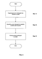
- the wash method starts with placing a second detergent in a position where the second detergent can be aspirated by the reagent pipette. Then, the reagent pipette is driven such that the second detergent is aspirated and delivered into the reaction cuvette (hereinafter may be referred to as the first step). Then, the reaction turntable is driven to move the reaction cuvette holding the second detergent into the position of a specified one of the wash nozzles of the reaction cuvette wash unit (hereinafter may be referred to as the second step). The wash nozzle is made to descend to aspirate the second detergent from inside the reaction cuvette (hereinafter may be referred to as the third step).
- the reagent pipette is driven to aspirate the second detergent and to deliver it into the reaction cuvette.
- the reaction turntable is driven to move the reaction cuvette containing the second detergent into the specified cleaning nozzle of the reaction cuvette wash unit.
- the second detergent is aspirated from inside the reaction cuvette using this wash nozzle, thus cleaning the wash nozzle. Consequently, each wash nozzle of the reaction cuvette wash unit can be cleaned with simple structure and simple manipulations.
- FIG. 1 there is shown an automated clinical analyzer according to the invention.
- the automated clinical analyzer is configured including a sample turntable 4, a diluted sample turntable 6, a first reagent turntable 8, a second reagent turntable 10, and a reaction turntable 12.
- sample containers 2 Two rows of sample containers 2, each row consisting of a given number of sample containers 2, are set on the sample turntable 4 near its outer periphery. Each sample container 2 holds a sample therein.
- Two rows of diluent cuvettes 3 are set on the sample turntable 4 inside the two rows of the sample containers 2. Each diluent cuvette 3 in one row holds a calibration sample. Each diluent cuvette 3 in the other row holds a sample used for accuracy management.
- the sample turntable 4 is rotated, the sample containers 2 and diluted sample containers 3 on the turntable 4 are rotated at given speeds to given positions. Special diluting fluids, probes, and detergents for washing the diluted sample containers may be set at inner positions.
- a given number of first reagent containers 7 holding a first reagent in cold storage are set on the first reagent turntable 8.
- a given number of second reagent containers 9 holding a second reagent in cold storage are set on the second reagent turntable 10.
- a given number of reaction cuvettes 11 are set on the reaction turntable 12.
- a diluted sample taken from one diluted sample container 5 on the diluted sample turntable 6, an aliquot of the first reagent taken from one first reagent container 7 on the first reagent turntable 8, and an aliquot of the second reagent taken from one second reagent container 9 on the second reagent turntable 10 are put in each of the reaction cuvettes 11 such that the sample and reagents react with each other.
- a sample dilution pipette 13 is disposed beside the sample turntable 4.
- all pipettes are disposed on the side of the rotating ends of rotating arms.
- the sample dilution pipette 13 is driven to the left and right and up and down by a sample dilution pipette left/right and up/down moving mechanism (not shown).
- the pipette 13 reciprocates through a wash unit (not shown) between the sample turntable 4 and the diluted sample turntable 6 by rotating to the left and right.
- a sample pump (not shown) is operated to aspirate a given amount of sample.
- the pipette has an access to a selected one of the diluted sample containers 5 at a given position of the diluted sample turntable 6, the pipette delivers a given amount of diluent (usually, normal saline solution) supplied from the pipette 13 itself together with the sample.
- the sample is diluted by a desired factor within the diluted sample container 5.
- the pipette 13 is cleaned by a sample diluted pipette wash unit (not shown).
- a sampling pipette 14 Arranged around the diluted sample turntable 6 are a sampling pipette 14, a sample dilution stirrer 15, and a diluted sample container wash unit 16, in addition to the sample dilution pipette 13.
- the stirrer 15 is driven up and down by a stirrer vertical drive mechanism (not shown). Also, a stirrer rod (not shown) is rotated. The stirrer rod advances into the diluted sample within a selected one of the diluted sample containers 5 on the diluted sample turntable 6 and rotates, thus diluting the sample uniformly.
- the diluted sample container wash unit 16 delivers the diluted sample into the reaction cuvettes 11 and then cleans the sampling pipette 14 as described later.
- the diluted sample container wash unit 16 has a plurality of diluted sample container wash nozzles and operates to aspirate the already detected, diluted sample from inside the diluted sample container 5 by a waste pump (not shown) via these wash nozzles, to vent the sample into the waste tank, to supply a detergent into this diluted sample container 5 by a wash pump (not shown) for washing the inside of the diluted sample container 5 with the detergent, and then to discharge the detergent into the waste tank so as to dry the inside of the diluted sample container.
- the diluted sample inside the diluted sample container 5 is stirred by the sample dilution stirrer 15 to dilute the sample uniformly.
- the diluted sample turntable 6 is moved in steps of a length having no common factor with the total number of the diluted sample containers 5 arranged on a circumference on the diluted sample turntable 6.
- the sampling pipette 14 is driven to the left and right and up and down by the sampling pipette left/right and up/down drive mechanism (not shown) to reciprocatively rotate to the left and right between the diluted sample turntable 6 and the reaction turntable 12.
- the diluted sample pump (not shown) is operated to aspirate a given amount of diluted sample.
- the pipette ascends or descends and gains access to the reaction cuvette 11 at a given position of the reaction turntable 12, the aspirated diluted sample is delivered into the reaction cuvettes 11.
- a first reagent pipette 17 Arranged around the reaction turntable 12 are a first reagent pipette 17, a second reagent pipette 18, a first reaction stirrer 19, a second reaction stirrer 20, a multi-wavelength spectrophotometer 21 being a detector, a reaction bath 22, and a reaction cuvette wash unit 23 in addition to the sampling pipette 14.
- the first reagent pipette 17 is driven to the left and right and up and down by a first reagent pipette left/right and up/down drive mechanism (not shown) to reciprocate between the reaction turntable 12 and the first reagent turntable 8 by rotating to the left and right.
- a first reagent pipette 17 ascends or descends and gains access to the first reagent container 7 at a given position of the first reagent turntable 8
- a first reagent pump (not shown) is operated to aspirate a given amount of first reagent.
- the aspirated first reagent is delivered into the reaction cuvette 11.
- a given amount of condensed reagent is diluted with pure water or room-temperature water and aliquotted by a first reagent sampling means and a first reagent diluting-and-aliquotting means (described later) in the present embodiment.
- the first reaction stirrer 19 is driven up and down by a stirrer up/down drive mechanism (not shown) and has a stirrer rod (not shown) that spinning and reciprocating motion. After advancing into the diluted sample and first reagent in the given reaction cuvette 11 on the reaction turntable 12, the stirrer rod spinning and reciprocating motion. This permits reaction of the diluted sample to be effected uniformly and quickly.
- the second reagent pipette 18 is driven to the left and right and up and down by a second reagent pipette left/right and up/down drive mechanism (not shown) to reciprocate between the reaction turntable 12 and the second reagent turntable 10 by rotating to the left and right.
- a second reagent pipette pump (not shown) is operated to aspirate a given amount of second reagent.
- the aspirated second reagent is delivered into the reaction cuvette 11.
- a given amount of condensed reagent is diluted with pure water or room-temperature water and aliquotted in the present embodiment by a second reagent sampling means and a second reagent dilution-and-aliquotting means (described later) in the same way as in the case of the first reagent.
- the second reaction stirrer 20 is driven up and down by a stirrer up/down drive mechanism (not shown) and has a stirrer rod (not shown) which spinning and reciprocating motion. After advancing into the diluted sample and second reagent in the given reaction cuvette 11 on the reaction turntable 12, the stirrer rod spinning and reciprocating motion. As a result, the diluted sample reacts uniformly and quickly.
- the multi-wavelength spectrophotometer 21 measures the absorbance of the diluted sample in the reaction cuvette 11 and detects how the diluted sample reacts inside the reaction cuvette 11.
- the reaction bath 22 maintains constant the temperature of the reaction cuvette 11 on the reaction turntable 12 at all times.
- the reaction cuvette wash unit 23 has the structure shown in FIG. 5 .
- the wash unit 23 performs analysis routine cleaning using the first detergent by means of the reaction cuvette wash nozzles S1-S5, I1-I4, and drying nozzle SD.
- reaction turntable 12 is moved in steps of a length having no common factor with the total number of the reaction cuvettes 11 arranged on a circumference on the reaction turntable 12.
- FIG. 2 is a block diagram of the electrical components of the inventive portions.
- the electrical components include control means 51 that receives instructions from a touch panel 53 which displays the states of a first switch for starting wash of the reaction cuvette wash nozzles of the reaction cuvette wash unit 23, a second switch for starting wash of the diluted sample container wash nozzles of the diluted sample container wash unit 16, a switch for specifying the number of wash steps performed by each wash nozzle, and a switch for specifying the types of detergents used to clean the wash nozzles.
- the control means 51 controls the operation of the sample turntable 4, diluted sample turntable 6, first reagent turntable 8, second reagent turntable 10, reaction turntable 12, sample dilution pipette 13, sampling pipette 14, diluted sample container wash unit 16, reaction cuvette wash unit 23, first reagent pipette 17, and second reagent pipette 18.
- FIG. 3 is a flowchart illustrating the operation of the control means.
- plural detergent containers 7W holding plural types of the second detergent e.g., alkaline detergent, acidic detergent, and cleaning agent (such as hypochlorite detergent) for nozzle cleaning are arranged on a reagent turntable (in the present embodiment, the first reagent turntable 8).
- the second detergent e.g., alkaline detergent, acidic detergent, and cleaning agent (such as hypochlorite detergent)
- step 1 When the first switch of the touch panel 53 is depressed (turned on) (step 1), the control means 51 moves the first reagent turntable 8 into a position where the first reagent pipette 17 can suck any one of the detergent containers 7W containing the second detergent (step 2).
- the second detergent is aspirated by the first reagent pipette 17 (step 3), and the detergents are delivered into the reaction cuvettes 11 on the reaction cuvette turntable (herein also referred to as the reaction turntable) 12 (step 4).
- the quantity of detergent of this time is set to quantity to reach the height of the overflow nozzles.
- the reaction turntable 12 is driven to move the reaction cuvette 11 from which the second detergent is scheduled to be next delivered into a position where the first reagent pipette 17 can aspirate and deliver the detergents (step 5).
- Steps 3-5 are performed as many times as the number of the nozzles of the reaction cuvette wash unit 23 which perform sucking operations (step 6) . Consequently, the second detergent is injected into the five reaction cuvettes A-E corresponding to the array of the nozzles S1-S5 to be cleaned as shown in FIG. 6A .
- the reaction turntable 12 is driven to bring the reaction cuvettes 11 of E-A containing the detergents to under the nozzles S1-S5 of the reaction cuvette wash unit 23 to be cleaned as shown in FIG. 6B (step 7).
- the nozzles of the wash unit 23 are made to descend (step 8).
- the second detergent is aspirated from inside the reaction cuvettes 11 via the nozzles S1-S5 and via the anti-overflow nozzles (step 9).
- Steps 3-9 are performed as many times as a specified number of cleaning steps (step 10).
- Steps 3-10 are performed as many times as a specified number of types of the second detergent while varying the type of the second detergent used (step 11).
- reaction cuvette wash unit 23 is driven to clean and dry the inside of the reaction cuvette 11 used for the nozzle cleaning (step 12).
- the aforementioned analysis routine cleaning may be done for all the reaction cuvettes.
- the first wash process has been described so far.
- a separately prepared second detergent is supplied into the reaction cuvettes to clean their insides (step 13).
- the used detergent is aspirated by the reaction cuvette wash nozzles and discharged (step 14).
- water is poured into the reaction cuvettes to wash out the residues of the second detergent in the reaction cuvettes.
- the water is then drawn in by the reaction cuvette wash nozzles and discharged (step 15).
- the dilution cleaner 16 for cleaning the diluted sample containers is also provided with plural wash nozzles which can be similarly cleaned. That is, plural detergent containers holding plural types of detergents (such as alkaline detergent, acidic detergent, and hypochlorite detergent) are previously held on the sample turntable 4. If the second switch for starting wash of the diluted sample container wash nozzles of the diluted sample container wash unit 16 is turned on, then the control means 51 delivers the detergents into the diluted sample containers 5 on the diluted sample turntable 6 by the use of the sample dilution pipette 13 and cleans the wash nozzles of the diluted sample container wash unit 16 with the detergents within the diluted sample container 5, in the same way as when the first switch is turned on. Then, the dilution wash unit is rinsed with an alkaline detergent, thus terminating the cleaning process.
- plural detergent containers holding plural types of detergents such as alkaline detergent, acidic detergent, and hypochlorite detergent
- the reaction cuvette wash nozzles of the reaction cuvette wash unit 23 can be cleaned with simple manipulations. Furthermore, the diluted sample wash nozzles of the diluted sample container wash unit 16 can be cleaned with a simple structure and easy manipulations. It is to be noted that the present invention is not restricted to the above embodiment.
- control means 51 uses the detergent put in the first reagent containers 7 on the first reagent turntable 8.
- control means may use the detergent put in the second reagent containers 9 on the second reagent turntable 10.
- the operation for washing the wash nozzles of the wash unit of the present embodiment may be interlocked with normal operation of the diluted sample container wash unit 16 to clean the diluted sample containers 5 and with normal operation of the reaction cuvette wash unit 23 to clean the reaction cuvettes 11.
- the interlocking may be activated or deactivated using the touch panel 53.
- the power supply of the automated analyzer may be automatically turned off.
- the automatic power-off mode may be selectively deactivated from the touch panel 53.
- steps 1-4 and steps 7-9 may be performed. Then, the process may return to step 1. Then, steps 1-4 and steps 7-9 may be performed as many times as there are nozzles.
- the reaction turntable 12 is driven to move this reaction cuvette 11 into the position of the nozzle S5 as shown in FIG. 6B . The second detergent is sucked from this reaction cuvette by the nozzle S5.
- the second detergent cooperating with the reagent pipette 17 to perform next nozzle cleaning can be injected into the reaction cuvette 11.
- the nozzle can be cleaned in substantially the same time as for the above-described embodiment.
- the containers 7W containing detergents for nozzle cleaning are held on the first reagent turntable 8.
- the invention is not restricted to this arrangement.
- the containers 7W may also be held on the second reagent turntable 10.
- the containers 7W may be placed at any locations if suction using either the first reagent pipette 17 or the second reagent pipette 18 is possible.
Landscapes
- Chemical & Material Sciences (AREA)
- Life Sciences & Earth Sciences (AREA)
- Health & Medical Sciences (AREA)
- General Health & Medical Sciences (AREA)
- Immunology (AREA)
- Pathology (AREA)
- Analytical Chemistry (AREA)
- Biochemistry (AREA)
- Physics & Mathematics (AREA)
- General Physics & Mathematics (AREA)
- Chemical Kinetics & Catalysis (AREA)
- General Chemical & Material Sciences (AREA)
- Engineering & Computer Science (AREA)
- Biomedical Technology (AREA)
- Molecular Biology (AREA)
- Hydrology & Water Resources (AREA)
- Automatic Analysis And Handling Materials Therefor (AREA)
Applications Claiming Priority (3)
| Application Number | Priority Date | Filing Date | Title |
|---|---|---|---|
| JP2011131968 | 2011-06-14 | ||
| JP2012099644 | 2012-04-25 | ||
| JP2012116107A JP5836195B2 (ja) | 2011-06-14 | 2012-05-22 | 臨床検査用分析装置および臨床検査用分析装置における洗浄方法 |
Publications (3)
| Publication Number | Publication Date |
|---|---|
| EP2535720A2 true EP2535720A2 (de) | 2012-12-19 |
| EP2535720A3 EP2535720A3 (de) | 2017-11-22 |
| EP2535720B1 EP2535720B1 (de) | 2020-06-17 |
Family
ID=46466115
Family Applications (1)
| Application Number | Title | Priority Date | Filing Date |
|---|---|---|---|
| EP12171654.2A Active EP2535720B1 (de) | 2011-06-14 | 2012-06-12 | Instrument und Verfahren für klinische Untersuchungen, und Reinigungsverfahren dafür |
Country Status (5)
| Country | Link |
|---|---|
| US (2) | US20120318302A1 (de) |
| EP (1) | EP2535720B1 (de) |
| JP (1) | JP5836195B2 (de) |
| KR (1) | KR101373440B1 (de) |
| CN (1) | CN102830238B (de) |
Cited By (2)
| Publication number | Priority date | Publication date | Assignee | Title |
|---|---|---|---|---|
| CN113917169A (zh) * | 2021-10-29 | 2022-01-11 | 宁波普瑞柏生物技术股份有限公司 | 全自动蛋白分析仪 |
| CN117368471A (zh) * | 2023-10-12 | 2024-01-09 | 青岛英赛特生物科技有限公司 | 一种外源性禽白血病抗原检测试剂盒及检测方法 |
Families Citing this family (24)
| Publication number | Priority date | Publication date | Assignee | Title |
|---|---|---|---|---|
| CN104508493B (zh) * | 2012-07-25 | 2016-07-06 | 株式会社日立高新技术 | 自动分析装置 |
| KR101442066B1 (ko) * | 2012-11-27 | 2014-09-18 | 주식회사 엘지생명과학 | 기울임 회전 교반기를 포함하는 체외 자동 진단 장치 |
| EP2988133B1 (de) * | 2013-04-18 | 2020-01-22 | Hitachi High-Technologies Corporation | Automatische analysevorrichtung |
| US9897622B2 (en) * | 2013-04-22 | 2018-02-20 | Hitachi High-Technologies Corporation | Automatic analyzer |
| JP6651443B2 (ja) * | 2013-10-17 | 2020-02-19 | シーメンス・ヘルスケア・ダイアグノスティックス・インコーポレーテッドSiemens Healthcare Diagnostics Inc. | コンパクトで高容量の分析機器基本構造 |
| JP6379693B2 (ja) * | 2014-06-04 | 2018-08-29 | 東ソー株式会社 | ノズルの自動洗浄を実施する自動分析装置 |
| US20150370060A1 (en) * | 2014-06-23 | 2015-12-24 | Resolution Biomedical, Inc. | Microscope slide with etched shapes |
| WO2016130962A1 (en) | 2015-02-13 | 2016-08-18 | Abbott Laboratories | Automated storage modules for diagnostic analyzer liquids and related systems and methods |
| CN105396853A (zh) * | 2015-12-11 | 2016-03-16 | 谢文娟 | 一种试管清洗装置 |
| EP3415921B1 (de) * | 2016-03-25 | 2021-11-10 | Hitachi High-Tech Corporation | Automatisierter analysator |
| CN106552797B (zh) * | 2016-11-02 | 2019-01-22 | 福建农林大学 | 一种试剂容器清洗装置及其清洗方法 |
| US11656238B2 (en) | 2017-01-23 | 2023-05-23 | Hitachi High-Tech Corporation | Automatic analyzer |
| JP6887880B2 (ja) * | 2017-05-30 | 2021-06-16 | 日本電子株式会社 | 自動分析装置及びプログラム |
| JP7054616B2 (ja) * | 2017-11-13 | 2022-04-14 | 日本電子株式会社 | 自動分析装置 |
| EP3732491B1 (de) * | 2017-12-29 | 2024-11-06 | Beckman Coulter, Inc. | Probenanalysesystem mit einer sondenwaschanordnung und verfahren zu seiner verwendung |
| JP6928712B2 (ja) * | 2018-03-16 | 2021-09-01 | 株式会社日立ハイテク | 自動分析装置 |
| JP6876650B2 (ja) * | 2018-03-30 | 2021-05-26 | 日本電子株式会社 | 自動分析装置および自動分析方法 |
| CN108508140A (zh) * | 2018-06-22 | 2018-09-07 | 济南盛泰电子科技有限公司 | 一种全自动高锰酸盐指数分析系统 |
| JP6995085B2 (ja) * | 2019-05-31 | 2022-01-14 | 日本電子株式会社 | 自動分析装置及び自動分析装置の制御方法 |
| JP6915010B2 (ja) * | 2019-09-20 | 2021-08-04 | 日本電子株式会社 | 自動分析装置および自動分析方法 |
| CN114981663A (zh) * | 2020-02-07 | 2022-08-30 | 积水医疗株式会社 | 自动分析装置 |
| CN115443410A (zh) * | 2020-04-30 | 2022-12-06 | 德赛技术有限公司 | 用于液体样品自动诊断分析的设备 |
| US20230314458A1 (en) * | 2020-09-29 | 2023-10-05 | Hitachi High-Tech Corporation | Automatic analyzer, work support device, and automatic analysis system |
| CN114112540B (zh) * | 2021-12-24 | 2023-08-29 | 蚌埠学院 | 一种在线快速水质余氯分析仪 |
Family Cites Families (20)
| Publication number | Priority date | Publication date | Assignee | Title |
|---|---|---|---|---|
| JPH01118771A (ja) * | 1987-10-31 | 1989-05-11 | Olympus Optical Co Ltd | 反応管洗浄装置 |
| JP2786767B2 (ja) * | 1991-12-17 | 1998-08-13 | 株式会社日立製作所 | 自動分析装置および容器の汚染判定方法 |
| JP3230277B2 (ja) * | 1992-05-15 | 2001-11-19 | 東ソー株式会社 | 液体の排出モニタ−方法及びそのための装置 |
| JP2950698B2 (ja) * | 1993-01-11 | 1999-09-20 | 株式会社日立製作所 | 洗浄機能付き自動分析装置 |
| JPH0749350A (ja) * | 1993-08-03 | 1995-02-21 | Nippon Tectron Co Ltd | 自動分析装置 |
| JPH08101214A (ja) * | 1994-09-30 | 1996-04-16 | Shimadzu Corp | 臨床用自動分析装置 |
| JP3229915B2 (ja) * | 1995-01-19 | 2001-11-19 | 日本電子株式会社 | 生化学自動分析装置 |
| JP3419431B2 (ja) * | 1996-08-21 | 2003-06-23 | 日本電子株式会社 | 生化学自動分析装置における洗浄装置 |
| JP3448436B2 (ja) * | 1996-08-21 | 2003-09-22 | 日本電子株式会社 | 生化学自動分析装置における洗浄装置 |
| JP2001091518A (ja) * | 1999-09-20 | 2001-04-06 | Hitachi Ltd | 自動分析装置 |
| JP2004279289A (ja) * | 2003-03-18 | 2004-10-07 | Hitachi High-Technologies Corp | 自動分析装置 |
| JP2007047027A (ja) * | 2005-08-10 | 2007-02-22 | Toshiba Corp | 自動分析装置及びその洗浄方法 |
| CN101031786A (zh) * | 2005-08-26 | 2007-09-05 | 先进科技股份有限公司 | 流动分析系统 |
| JP2008128662A (ja) * | 2006-11-16 | 2008-06-05 | Olympus Corp | 分析装置 |
| JP2009068879A (ja) | 2007-09-11 | 2009-04-02 | Olympus Corp | 分注装置、分注装置の分注ノズル洗浄方法及び自動分析装置 |
| JP4977582B2 (ja) * | 2007-11-13 | 2012-07-18 | 株式会社日立ハイテクノロジーズ | 自動分析装置 |
| CN101726620B (zh) * | 2008-10-30 | 2013-11-13 | 深圳迈瑞生物医疗电子股份有限公司 | 生化分析仪及其流体元件清洁方法 |
| JP5124497B2 (ja) * | 2009-01-30 | 2013-01-23 | 株式会社日立ハイテクノロジーズ | 自動分析装置 |
| JP5337600B2 (ja) | 2009-07-03 | 2013-11-06 | 株式会社日立ハイテクノロジーズ | 自動分析装置及び自動分析装置の制御方法 |
| JP2011112540A (ja) | 2009-11-27 | 2011-06-09 | Beckman Coulter Inc | 分注装置および分析システム |
-
2012
- 2012-05-22 JP JP2012116107A patent/JP5836195B2/ja active Active
- 2012-06-11 KR KR1020120061884A patent/KR101373440B1/ko active Active
- 2012-06-12 EP EP12171654.2A patent/EP2535720B1/de active Active
- 2012-06-13 US US13/495,116 patent/US20120318302A1/en not_active Abandoned
- 2012-06-14 CN CN201210196757.3A patent/CN102830238B/zh active Active
-
2016
- 2016-10-19 US US15/297,827 patent/US10254302B2/en active Active
Non-Patent Citations (1)
| Title |
|---|
| None |
Cited By (3)
| Publication number | Priority date | Publication date | Assignee | Title |
|---|---|---|---|---|
| CN113917169A (zh) * | 2021-10-29 | 2022-01-11 | 宁波普瑞柏生物技术股份有限公司 | 全自动蛋白分析仪 |
| CN117368471A (zh) * | 2023-10-12 | 2024-01-09 | 青岛英赛特生物科技有限公司 | 一种外源性禽白血病抗原检测试剂盒及检测方法 |
| CN117368471B (zh) * | 2023-10-12 | 2024-04-02 | 青岛英赛特生物科技有限公司 | 一种外源性禽白血病抗原检测试剂盒及检测方法 |
Also Published As
| Publication number | Publication date |
|---|---|
| US20170131313A1 (en) | 2017-05-11 |
| EP2535720A3 (de) | 2017-11-22 |
| KR101373440B1 (ko) | 2014-03-13 |
| US10254302B2 (en) | 2019-04-09 |
| JP5836195B2 (ja) | 2015-12-24 |
| EP2535720B1 (de) | 2020-06-17 |
| JP2013242238A (ja) | 2013-12-05 |
| CN102830238A (zh) | 2012-12-19 |
| CN102830238B (zh) | 2014-07-16 |
| US20120318302A1 (en) | 2012-12-20 |
| KR20120138658A (ko) | 2012-12-26 |
Similar Documents
| Publication | Publication Date | Title |
|---|---|---|
| US10254302B2 (en) | Method for clinical examinations and cleaning method therefor | |
| JP3677298B2 (ja) | 自動化学分析装置 | |
| US20170082616A1 (en) | Fully-automatic immunofluorescence quantitative analysis apparatus and detection method | |
| EP0825444B1 (de) | Waschgerät für automatische Analysevorrichtung | |
| EP2372371A2 (de) | Automatischer Analysator | |
| US9746398B2 (en) | Apparatus and method for automated analysis | |
| JP5232585B2 (ja) | 分析装置およびプローブ洗浄方法 | |
| JP6453219B2 (ja) | 自動分析装置 | |
| WO2012105398A1 (ja) | 自動分析装置 | |
| CN111936864B (zh) | 自动分析装置 | |
| JP6249626B2 (ja) | 自動分析装置 | |
| EP3422017A1 (de) | Automatische analysevorrichtung und reinigungsverfahren | |
| JP5661259B2 (ja) | 自動分析装置 | |
| EP1335205A2 (de) | Automatische Analysevorrichtung | |
| JP2001133466A (ja) | 自動分析装置 | |
| CN110320380B (zh) | 自动分析装置和自动分析方法 | |
| CN114019178A (zh) | 一种全自动免疫生化一体分析仪及使用方法 | |
| JP2010286420A (ja) | 分注ノズルの洗浄方法,自動分析装置、および容器 | |
| JP4175916B2 (ja) | 自動分析装置 | |
| JP2008304334A (ja) | 分注装置及び自動分析装置 | |
| CN216696352U (zh) | 一种全自动免疫生化一体分析仪 | |
| CN214310119U (zh) | 样本分析装置 | |
| CN114544994A (zh) | 一种样本分析装置和样本分析方法 | |
| JP2005291729A (ja) | 生化学分析装置 | |
| CN116893274A (zh) | 样本分析仪及清洗控制方法 |
Legal Events
| Date | Code | Title | Description |
|---|---|---|---|
| PUAI | Public reference made under article 153(3) epc to a published international application that has entered the european phase |
Free format text: ORIGINAL CODE: 0009012 |
|
| AK | Designated contracting states |
Kind code of ref document: A2 Designated state(s): AL AT BE BG CH CY CZ DE DK EE ES FI FR GB GR HR HU IE IS IT LI LT LU LV MC MK MT NL NO PL PT RO RS SE SI SK SM TR |
|
| AX | Request for extension of the european patent |
Extension state: BA ME |
|
| PUAL | Search report despatched |
Free format text: ORIGINAL CODE: 0009013 |
|
| AK | Designated contracting states |
Kind code of ref document: A3 Designated state(s): AL AT BE BG CH CY CZ DE DK EE ES FI FR GB GR HR HU IE IS IT LI LT LU LV MC MK MT NL NO PL PT RO RS SE SI SK SM TR |
|
| AX | Request for extension of the european patent |
Extension state: BA ME |
|
| RIC1 | Information provided on ipc code assigned before grant |
Ipc: G01N 35/04 20060101ALN20171013BHEP Ipc: G01N 35/02 20060101ALI20171013BHEP Ipc: G01N 35/10 20060101AFI20171013BHEP |
|
| STAA | Information on the status of an ep patent application or granted ep patent |
Free format text: STATUS: REQUEST FOR EXAMINATION WAS MADE |
|
| 17P | Request for examination filed |
Effective date: 20180430 |
|
| RBV | Designated contracting states (corrected) |
Designated state(s): AL AT BE BG CH CY CZ DE DK EE ES FI FR GB GR HR HU IE IS IT LI LT LU LV MC MK MT NL NO PL PT RO RS SE SI SK SM TR |
|
| STAA | Information on the status of an ep patent application or granted ep patent |
Free format text: STATUS: EXAMINATION IS IN PROGRESS |
|
| 17Q | First examination report despatched |
Effective date: 20190423 |
|
| RIC1 | Information provided on ipc code assigned before grant |
Ipc: G01N 35/04 20060101ALN20191107BHEP Ipc: G01N 35/10 20060101AFI20191107BHEP Ipc: G01N 35/02 20060101ALI20191107BHEP |
|
| GRAP | Despatch of communication of intention to grant a patent |
Free format text: ORIGINAL CODE: EPIDOSNIGR1 |
|
| STAA | Information on the status of an ep patent application or granted ep patent |
Free format text: STATUS: GRANT OF PATENT IS INTENDED |
|
| INTG | Intention to grant announced |
Effective date: 20200108 |
|
| GRAS | Grant fee paid |
Free format text: ORIGINAL CODE: EPIDOSNIGR3 |
|
| GRAA | (expected) grant |
Free format text: ORIGINAL CODE: 0009210 |
|
| STAA | Information on the status of an ep patent application or granted ep patent |
Free format text: STATUS: THE PATENT HAS BEEN GRANTED |
|
| AK | Designated contracting states |
Kind code of ref document: B1 Designated state(s): AL AT BE BG CH CY CZ DE DK EE ES FI FR GB GR HR HU IE IS IT LI LT LU LV MC MK MT NL NO PL PT RO RS SE SI SK SM TR |
|
| REG | Reference to a national code |
Ref country code: GB Ref legal event code: FG4D |
|
| REG | Reference to a national code |
Ref country code: CH Ref legal event code: EP |
|
| REG | Reference to a national code |
Ref country code: DE Ref legal event code: R096 Ref document number: 602012070698 Country of ref document: DE |
|
| REG | Reference to a national code |
Ref country code: IE Ref legal event code: FG4D |
|
| REG | Reference to a national code |
Ref country code: AT Ref legal event code: REF Ref document number: 1281967 Country of ref document: AT Kind code of ref document: T Effective date: 20200715 |
|
| PG25 | Lapsed in a contracting state [announced via postgrant information from national office to epo] |
Ref country code: SE Free format text: LAPSE BECAUSE OF FAILURE TO SUBMIT A TRANSLATION OF THE DESCRIPTION OR TO PAY THE FEE WITHIN THE PRESCRIBED TIME-LIMIT Effective date: 20200617 Ref country code: LT Free format text: LAPSE BECAUSE OF FAILURE TO SUBMIT A TRANSLATION OF THE DESCRIPTION OR TO PAY THE FEE WITHIN THE PRESCRIBED TIME-LIMIT Effective date: 20200617 Ref country code: GR Free format text: LAPSE BECAUSE OF FAILURE TO SUBMIT A TRANSLATION OF THE DESCRIPTION OR TO PAY THE FEE WITHIN THE PRESCRIBED TIME-LIMIT Effective date: 20200918 Ref country code: NO Free format text: LAPSE BECAUSE OF FAILURE TO SUBMIT A TRANSLATION OF THE DESCRIPTION OR TO PAY THE FEE WITHIN THE PRESCRIBED TIME-LIMIT Effective date: 20200917 Ref country code: FI Free format text: LAPSE BECAUSE OF FAILURE TO SUBMIT A TRANSLATION OF THE DESCRIPTION OR TO PAY THE FEE WITHIN THE PRESCRIBED TIME-LIMIT Effective date: 20200617 |
|
| REG | Reference to a national code |
Ref country code: LT Ref legal event code: MG4D |
|
| REG | Reference to a national code |
Ref country code: NL Ref legal event code: MP Effective date: 20200617 |
|
| PG25 | Lapsed in a contracting state [announced via postgrant information from national office to epo] |
Ref country code: LV Free format text: LAPSE BECAUSE OF FAILURE TO SUBMIT A TRANSLATION OF THE DESCRIPTION OR TO PAY THE FEE WITHIN THE PRESCRIBED TIME-LIMIT Effective date: 20200617 Ref country code: RS Free format text: LAPSE BECAUSE OF FAILURE TO SUBMIT A TRANSLATION OF THE DESCRIPTION OR TO PAY THE FEE WITHIN THE PRESCRIBED TIME-LIMIT Effective date: 20200617 Ref country code: HR Free format text: LAPSE BECAUSE OF FAILURE TO SUBMIT A TRANSLATION OF THE DESCRIPTION OR TO PAY THE FEE WITHIN THE PRESCRIBED TIME-LIMIT Effective date: 20200617 Ref country code: BG Free format text: LAPSE BECAUSE OF FAILURE TO SUBMIT A TRANSLATION OF THE DESCRIPTION OR TO PAY THE FEE WITHIN THE PRESCRIBED TIME-LIMIT Effective date: 20200917 |
|
| REG | Reference to a national code |
Ref country code: AT Ref legal event code: MK05 Ref document number: 1281967 Country of ref document: AT Kind code of ref document: T Effective date: 20200617 |
|
| PG25 | Lapsed in a contracting state [announced via postgrant information from national office to epo] |
Ref country code: NL Free format text: LAPSE BECAUSE OF FAILURE TO SUBMIT A TRANSLATION OF THE DESCRIPTION OR TO PAY THE FEE WITHIN THE PRESCRIBED TIME-LIMIT Effective date: 20200617 Ref country code: AL Free format text: LAPSE BECAUSE OF FAILURE TO SUBMIT A TRANSLATION OF THE DESCRIPTION OR TO PAY THE FEE WITHIN THE PRESCRIBED TIME-LIMIT Effective date: 20200617 |
|
| PG25 | Lapsed in a contracting state [announced via postgrant information from national office to epo] |
Ref country code: CZ Free format text: LAPSE BECAUSE OF FAILURE TO SUBMIT A TRANSLATION OF THE DESCRIPTION OR TO PAY THE FEE WITHIN THE PRESCRIBED TIME-LIMIT Effective date: 20200617 Ref country code: RO Free format text: LAPSE BECAUSE OF FAILURE TO SUBMIT A TRANSLATION OF THE DESCRIPTION OR TO PAY THE FEE WITHIN THE PRESCRIBED TIME-LIMIT Effective date: 20200617 Ref country code: IT Free format text: LAPSE BECAUSE OF FAILURE TO SUBMIT A TRANSLATION OF THE DESCRIPTION OR TO PAY THE FEE WITHIN THE PRESCRIBED TIME-LIMIT Effective date: 20200617 Ref country code: PT Free format text: LAPSE BECAUSE OF FAILURE TO SUBMIT A TRANSLATION OF THE DESCRIPTION OR TO PAY THE FEE WITHIN THE PRESCRIBED TIME-LIMIT Effective date: 20201019 Ref country code: AT Free format text: LAPSE BECAUSE OF FAILURE TO SUBMIT A TRANSLATION OF THE DESCRIPTION OR TO PAY THE FEE WITHIN THE PRESCRIBED TIME-LIMIT Effective date: 20200617 Ref country code: ES Free format text: LAPSE BECAUSE OF FAILURE TO SUBMIT A TRANSLATION OF THE DESCRIPTION OR TO PAY THE FEE WITHIN THE PRESCRIBED TIME-LIMIT Effective date: 20200617 Ref country code: SM Free format text: LAPSE BECAUSE OF FAILURE TO SUBMIT A TRANSLATION OF THE DESCRIPTION OR TO PAY THE FEE WITHIN THE PRESCRIBED TIME-LIMIT Effective date: 20200617 Ref country code: EE Free format text: LAPSE BECAUSE OF FAILURE TO SUBMIT A TRANSLATION OF THE DESCRIPTION OR TO PAY THE FEE WITHIN THE PRESCRIBED TIME-LIMIT Effective date: 20200617 |
|
| PG25 | Lapsed in a contracting state [announced via postgrant information from national office to epo] |
Ref country code: PL Free format text: LAPSE BECAUSE OF FAILURE TO SUBMIT A TRANSLATION OF THE DESCRIPTION OR TO PAY THE FEE WITHIN THE PRESCRIBED TIME-LIMIT Effective date: 20200617 Ref country code: SK Free format text: LAPSE BECAUSE OF FAILURE TO SUBMIT A TRANSLATION OF THE DESCRIPTION OR TO PAY THE FEE WITHIN THE PRESCRIBED TIME-LIMIT Effective date: 20200617 Ref country code: IS Free format text: LAPSE BECAUSE OF FAILURE TO SUBMIT A TRANSLATION OF THE DESCRIPTION OR TO PAY THE FEE WITHIN THE PRESCRIBED TIME-LIMIT Effective date: 20201017 |
|
| REG | Reference to a national code |
Ref country code: DE Ref legal event code: R097 Ref document number: 602012070698 Country of ref document: DE |
|
| PLBE | No opposition filed within time limit |
Free format text: ORIGINAL CODE: 0009261 |
|
| STAA | Information on the status of an ep patent application or granted ep patent |
Free format text: STATUS: NO OPPOSITION FILED WITHIN TIME LIMIT |
|
| PG25 | Lapsed in a contracting state [announced via postgrant information from national office to epo] |
Ref country code: DK Free format text: LAPSE BECAUSE OF FAILURE TO SUBMIT A TRANSLATION OF THE DESCRIPTION OR TO PAY THE FEE WITHIN THE PRESCRIBED TIME-LIMIT Effective date: 20200617 |
|
| 26N | No opposition filed |
Effective date: 20210318 |
|
| PG25 | Lapsed in a contracting state [announced via postgrant information from national office to epo] |
Ref country code: SI Free format text: LAPSE BECAUSE OF FAILURE TO SUBMIT A TRANSLATION OF THE DESCRIPTION OR TO PAY THE FEE WITHIN THE PRESCRIBED TIME-LIMIT Effective date: 20200617 |
|
| PG25 | Lapsed in a contracting state [announced via postgrant information from national office to epo] |
Ref country code: MC Free format text: LAPSE BECAUSE OF FAILURE TO SUBMIT A TRANSLATION OF THE DESCRIPTION OR TO PAY THE FEE WITHIN THE PRESCRIBED TIME-LIMIT Effective date: 20200617 |
|
| REG | Reference to a national code |
Ref country code: CH Ref legal event code: PL |
|
| REG | Reference to a national code |
Ref country code: BE Ref legal event code: MM Effective date: 20210630 |
|
| PG25 | Lapsed in a contracting state [announced via postgrant information from national office to epo] |
Ref country code: LU Free format text: LAPSE BECAUSE OF NON-PAYMENT OF DUE FEES Effective date: 20210612 |
|
| PG25 | Lapsed in a contracting state [announced via postgrant information from national office to epo] |
Ref country code: LI Free format text: LAPSE BECAUSE OF NON-PAYMENT OF DUE FEES Effective date: 20210630 Ref country code: IE Free format text: LAPSE BECAUSE OF NON-PAYMENT OF DUE FEES Effective date: 20210612 Ref country code: CH Free format text: LAPSE BECAUSE OF NON-PAYMENT OF DUE FEES Effective date: 20210630 |
|
| PG25 | Lapsed in a contracting state [announced via postgrant information from national office to epo] |
Ref country code: BE Free format text: LAPSE BECAUSE OF NON-PAYMENT OF DUE FEES Effective date: 20210630 |
|
| PG25 | Lapsed in a contracting state [announced via postgrant information from national office to epo] |
Ref country code: HU Free format text: LAPSE BECAUSE OF FAILURE TO SUBMIT A TRANSLATION OF THE DESCRIPTION OR TO PAY THE FEE WITHIN THE PRESCRIBED TIME-LIMIT; INVALID AB INITIO Effective date: 20120612 Ref country code: CY Free format text: LAPSE BECAUSE OF FAILURE TO SUBMIT A TRANSLATION OF THE DESCRIPTION OR TO PAY THE FEE WITHIN THE PRESCRIBED TIME-LIMIT Effective date: 20200617 |
|
| PG25 | Lapsed in a contracting state [announced via postgrant information from national office to epo] |
Ref country code: MK Free format text: LAPSE BECAUSE OF FAILURE TO SUBMIT A TRANSLATION OF THE DESCRIPTION OR TO PAY THE FEE WITHIN THE PRESCRIBED TIME-LIMIT Effective date: 20200617 |
|
| PG25 | Lapsed in a contracting state [announced via postgrant information from national office to epo] |
Ref country code: TR Free format text: LAPSE BECAUSE OF FAILURE TO SUBMIT A TRANSLATION OF THE DESCRIPTION OR TO PAY THE FEE WITHIN THE PRESCRIBED TIME-LIMIT Effective date: 20200617 |
|
| PG25 | Lapsed in a contracting state [announced via postgrant information from national office to epo] |
Ref country code: MT Free format text: LAPSE BECAUSE OF FAILURE TO SUBMIT A TRANSLATION OF THE DESCRIPTION OR TO PAY THE FEE WITHIN THE PRESCRIBED TIME-LIMIT Effective date: 20200617 |
|
| PGFP | Annual fee paid to national office [announced via postgrant information from national office to epo] |
Ref country code: DE Payment date: 20250618 Year of fee payment: 14 |
|
| PGFP | Annual fee paid to national office [announced via postgrant information from national office to epo] |
Ref country code: GB Payment date: 20250618 Year of fee payment: 14 |
|
| PGFP | Annual fee paid to national office [announced via postgrant information from national office to epo] |
Ref country code: FR Payment date: 20250624 Year of fee payment: 14 |