EP2536018B1 - Wechselrichter mit einer Vielzahl von parallel geschalteten Wechselrichtern, und Verfahren - Google Patents
Wechselrichter mit einer Vielzahl von parallel geschalteten Wechselrichtern, und Verfahren Download PDFInfo
- Publication number
- EP2536018B1 EP2536018B1 EP11382204.3A EP11382204A EP2536018B1 EP 2536018 B1 EP2536018 B1 EP 2536018B1 EP 11382204 A EP11382204 A EP 11382204A EP 2536018 B1 EP2536018 B1 EP 2536018B1
- Authority
- EP
- European Patent Office
- Prior art keywords
- phase alternating
- voltage
- converter
- resulting
- inverters
- Prior art date
- Legal status (The legal status is an assumption and is not a legal conclusion. Google has not performed a legal analysis and makes no representation as to the accuracy of the status listed.)
- Not-in-force
Links
- 238000000034 method Methods 0.000 title claims description 21
- 238000006073 displacement reaction Methods 0.000 claims description 24
- 230000016507 interphase Effects 0.000 claims description 9
- 230000008030 elimination Effects 0.000 claims description 8
- 238000003379 elimination reaction Methods 0.000 claims description 8
- 230000009467 reduction Effects 0.000 claims description 8
- 238000004804 winding Methods 0.000 claims description 8
- 238000009413 insulation Methods 0.000 claims description 7
- 230000008878 coupling Effects 0.000 claims description 3
- 238000010168 coupling process Methods 0.000 claims description 3
- 238000005859 coupling reaction Methods 0.000 claims description 3
- 238000006243 chemical reaction Methods 0.000 claims description 2
- 239000004065 semiconductor Substances 0.000 description 7
- 230000005540 biological transmission Effects 0.000 description 6
- 238000010586 diagram Methods 0.000 description 4
- 238000005516 engineering process Methods 0.000 description 3
- 238000002623 insulin potentiation therapy Methods 0.000 description 3
- 230000003068 static effect Effects 0.000 description 2
- 230000008859 change Effects 0.000 description 1
- 230000006872 improvement Effects 0.000 description 1
- 230000003993 interaction Effects 0.000 description 1
- 238000004519 manufacturing process Methods 0.000 description 1
- 230000007935 neutral effect Effects 0.000 description 1
- 230000004044 response Effects 0.000 description 1
- 230000001360 synchronised effect Effects 0.000 description 1
Images



Classifications
-
- H—ELECTRICITY
- H02—GENERATION; CONVERSION OR DISTRIBUTION OF ELECTRIC POWER
- H02M—APPARATUS FOR CONVERSION BETWEEN AC AND AC, BETWEEN AC AND DC, OR BETWEEN DC AND DC, AND FOR USE WITH MAINS OR SIMILAR POWER SUPPLY SYSTEMS; CONVERSION OF DC OR AC INPUT POWER INTO SURGE OUTPUT POWER; CONTROL OR REGULATION THEREOF
- H02M7/00—Conversion of AC power input into DC power output; Conversion of DC power input into AC power output
- H02M7/42—Conversion of DC power input into AC power output without possibility of reversal
- H02M7/44—Conversion of DC power input into AC power output without possibility of reversal by static converters
- H02M7/48—Conversion of DC power input into AC power output without possibility of reversal by static converters using discharge tubes with control electrode or semiconductor devices with control electrode
- H02M7/493—Conversion of DC power input into AC power output without possibility of reversal by static converters using discharge tubes with control electrode or semiconductor devices with control electrode the static converters being arranged for operation in parallel
-
- H—ELECTRICITY
- H02—GENERATION; CONVERSION OR DISTRIBUTION OF ELECTRIC POWER
- H02M—APPARATUS FOR CONVERSION BETWEEN AC AND AC, BETWEEN AC AND DC, OR BETWEEN DC AND DC, AND FOR USE WITH MAINS OR SIMILAR POWER SUPPLY SYSTEMS; CONVERSION OF DC OR AC INPUT POWER INTO SURGE OUTPUT POWER; CONTROL OR REGULATION THEREOF
- H02M1/00—Details of apparatus for conversion
- H02M1/12—Arrangements for reducing harmonics from AC input or output
-
- H—ELECTRICITY
- H02—GENERATION; CONVERSION OR DISTRIBUTION OF ELECTRIC POWER
- H02M—APPARATUS FOR CONVERSION BETWEEN AC AND AC, BETWEEN AC AND DC, OR BETWEEN DC AND DC, AND FOR USE WITH MAINS OR SIMILAR POWER SUPPLY SYSTEMS; CONVERSION OF DC OR AC INPUT POWER INTO SURGE OUTPUT POWER; CONTROL OR REGULATION THEREOF
- H02M1/00—Details of apparatus for conversion
- H02M1/0043—Converters switched with a phase shift, i.e. interleaved
Definitions
- This invention relates to converters for converting energy in high-power environments, and in particular to converters for converting energy for transmission and/or distribution lines from a DC power. This invention also relates to control methods for electronic power converters.
- Electronic power converters are currently used in a wide range of applications where a DC/AC conversion is required, carried out by means of inverters comprised in said converters, such as variable-speed drives, variable-speed wind turbines, solar inverters, UPS (Uninterruptible Power Supplies) systems or FACTS (Flexible AC Transmission Systems) devices.
- inverters comprised in said converters, such as variable-speed drives, variable-speed wind turbines, solar inverters, UPS (Uninterruptible Power Supplies) systems or FACTS (Flexible AC Transmission Systems) devices.
- Inverters in electronic power converters comprise static semiconductor-type switches.
- the switching characteristics of the semiconductor devices currently available on the market enable the most suitable semiconductor for each type of application to be chosen.
- different families of semiconductors may be identified:
- the output voltage of the converter can be increased by increasing the number of levels of its output voltage, thereby increasing the power of the converter, which is achieved by using multi-level inverters.
- the quality of the wave of the output voltage increases with the number of levels.
- a three-level inverter for example, it is possible to obtain a five-level output voltage waveform.
- the greater the number of levels the greater the complexity in implementing the converter (of the inverters), as a result of which, and generally speaking, industrial applications are usually based on inverters or branches of up to two or three levels at most.
- the most commonly used solution in the manufacture of high-power converters for FACTS applications is the connection of three-phase inverters of two or three levels to each other by means of intermediate magnetic elements or transformers, so that thanks to said connection or combination, another increase in the output voltage and/or current, and, therefore, in the power of the converter, is achieved, the quality of the output wave also being capable of being improved.
- document US 3628123 A discloses the combination in parallel of two inverters by means of interphase transformers or IPTs.
- Document US 5337227 A discloses a system that comprises a plurality of interphase transformers connected in series in branch, each of them comprising two inputs to receive two alternating-voltage signals out of phase with each other at a predetermined angle for the elimination or reduction of predetermined harmonic components in a resulting alternating-voltage output signal of the interphase transformer, and a plurality of inverters to generate the alternating-voltage signals that receive the interphase transformers in a first branching stage.
- a plurality of output transformers can be included after the interphase transformers
- Document WO 93/23914 A1 discloses an electronic power converter comprising a plurality of inverters to generate a plurality of three-phase alternating-voltage signals from at least on DC power line.
- the electronic power converter comprises a plurality of inverters to generate a plurality of three-phase alternating-voltage signals from at least one DC power line, each inverter generating a three-phase alternating-voltage signal, and combination means for combining the inverters in parallel and obtain at least two resulting three-phase alternating-voltage signals, combining the alternating-voltage signals generated by said inverters thus being in parallel.
- the converter also comprises an output for a low-power and low-voltage three-phase alternating-voltage output signal, and a low-power and low-voltage transformer block in order to combine the resulting signals in series and provide the output signal, the transformer block being adapted to generate a specific phase displacement and a galvanic insulation between the resulting signals combined in series.
- DC power is converted into a plurality of three-phase alternating-voltage signals by means of a plurality of inverters, an inverter being used for each alternating-voltage signal, and the inverters are combined in parallel, generating at least two resulting three-phase alternating-voltage signals, the alternating-voltage signals being combined in parallel for this purpose.
- the resulting signals are also combined in series to obtain a low-power and low-voltage alternating-voltage output signal and, during the series combination, a specific phase displacement and a galvanic insulation is generated between the resulting signals that are combined.
- the converter 100 is of the VSC (Voltage Source Converter) type and converts DC power into alternating-voltage power to supply it to a load such as a high-voltage transmission and/or distribution line. Although it is a three-phase system, the figures and the description show and explain the converter 100 in single-wire form for the purpose of clarity.
- VSC Voltage Source Converter
- FIG. 1 shows, by way of example and in a schematic manner, an embodiment of the converter 100.
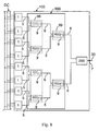
- the converter 100 is connected to a DC power line, and comprises a plurality of multi-level inverters 1, which can comprise three levels, as shown in Figure 2 , to convert the power of the DC line into different three-phase alternating-voltage signals 5, each inverter 1 generating a corresponding three-phase alternating-voltage signal 5, with three phases F1, F2 and F3, from the DC power line.
- the converter 100 also comprises a connection block 900 in order to combine the inverters 1 in parallel and obtain at least two resulting three-phase alternating-voltage signals 6, the three-phase alternating-voltage signals 5 generated by said inverters 1 being combined in parallel for that purpose.
- the converter 100 also comprises an output 7 for a low-power and low-voltage three-phase alternating-voltage output signal 30, and a low-power and low-voltage transformer block 200 in order to combine the resulting signals 6 in series and provide the output signal 30, the transformer block 200 being adapted to generate a specific phase displacement and a galvanic insulation between the resulting signals 6 that are combined in series.
- the transformer block 200 is of the low-power and low-voltage type, and comprises reduced dimensions as it does not have to generate a galvanic insulation in high voltage between the input voltages 6 and the output voltage 30, and its output (the output signal 30) can be supplied to the load (such as a distribution and/or power line) through a single coupling transformer (not shown in the figures) that comprises a single primary and a single secondary.
- the load such as a distribution and/or power line
- a single coupling transformer not shown in the figures
- an output signal 30 is obtained by using a reduced number of components or elements necessary for supplying a high power level to the load.
- the transformer block 200 is adapted in order to combine the resulting signals 6 in series in twos, comprising a transformer unit 20 for each combination in series.
- the converter 100 thus comprises as many transformer units 20 as are needed to generate a single output signal 30 from the quantity of resulting signals 6 it comprises.
- Figure 3 shows an example of a possible embodiment of a transformer block 200 for two resulting signals 6, comprising a transformer unit 20.
- Figure 4 shows an example of a possible embodiment of a transformer block 200 for three resulting signals 6, comprising two transformer units 20.
- Figure 5 shows an example of a possible embodiment of a transformer block 200 for four resulting signals 6, comprising three transformer units 20.
- a transformer unit 20 can receive, in order to combine them in series, two resulting signals 6 originating from the connection block 900, a resulting signal 6 originating from the connection block 900 and an intermediate alternating-voltage signal 201 originating from another transformer unit 20, or two intermediate alternating-voltage signals 201 originating from two transformer units 20.
- each transformer unit 20 can comprise a delta winding 21 which receives a resulting signal 6 (or an intermediate signal 201), and a wye winding 22 which receives another resulting signal 6 (or an intermediate signal 201), both windings 21 and 22 being coupled magnetically and the wye winding 22 comprising the neutral opened, the output signal of the wye winding 22 and, therefore, of the transformer unit 20 corresponding with an intermediate signal 201 or with the output signal 30.
- connection block 900 can be adapted in order to combine in parallel the alternating-voltage signals 5 that the inverters 1 generate in twos, comprising a connection unit 9 for each combination.
- Each connection unit 9 can also comprise an interphase transformer or IPT, although other known means of achieving the combination in parallel of the inverters 1 can be used, with which the inverters 1 can be combined in twos or in larger groups.
- IPT interphase transformer
- the connection units 9 only receive the alternating-voltage signals 5 generated by the inverters 1, so that the converter 100 comprises a number of connection units 9 equal to half the inverters 1 it comprises.
- the converter 100 comprises six inverters 1 combined in parallel in twos by means of three connection units 9, although it can have more inverters 1 and, therefore, more connection units 9.
- the proportion of the number of connection units 9 in relation to the number of inverters 1 can change according to the manner in which the inverters 1 are combined in parallel.
- the transformer block 200 comprises a number of transformer units 20 equal to the number of inverters 1 comprised by the converter 100 divided by two, minus one.
- connection units 9 are adapted to receive alternating-voltage signals 5 originating from the inverters 1 and/or resulting signals 6 originating from connection units 9.
- the converter 100 can thus comprise a plurality of connection units 9 connected in series in branch, with as many branches 98 and 99 as connections in series, and a plurality of branches of connection units 9.
- the branching of the connection units 9 comprises two branches 98 and 99.
- the transformer block 200 comprises a number of transformer units 20 equal to the number of inverters 1 comprised by the converter 100 divided by the number of connection units 9 connected in series, minus one.
- Each transformer unit 20 generates, between the alternating-voltage signals 6, 201 it combines in series, a minimal phase displacement that can be equal to approximately a factor of 60°.
- the factor corresponds with the result of the equation 60/m, where m is the number of alternating-voltage signals 6 obtained by combining the groups of inverters 1 whose alternating-voltage output signals 5 are combined in parallel in a single combination.
- m is the number of alternating-voltage signals 6 obtained by combining the groups of inverters 1 whose alternating-voltage output signals 5 are combined in parallel in a single combination.
- the phase displacement can also be a factor of 360°, the factor corresponding with the result of the equation 1/ph, where ph is the number of total phases (number of inverters per three phases if it is a three-phase inverter).
- ph is the number of total phases (number of inverters per three phases if it is a three-phase inverter).
- a method to be used in a converter 100 such as the one described above (in any of its embodiments) is explained below.
- DC power is converted into a plurality of alternating-voltage signals 5 by means of a plurality of inverters 1, an inverter 1 being used for each alternating-voltage signal 5, and the alternating-voltage signals 5 combined in parallel, for example in twos and with interphase transformers as explained above, although other means of combining said alternating-voltage signals 5 in parallel can also be used, a resulting signal 6 being obtained from each combination.
- two resulting signals 6 are also combined in series to obtain a low-power and low-voltage alternating-voltage output signal 30 of the converter 100, and during the series combination, a specific phase displacement and a galvanic insulation is generated between the two resulting signals 6 that are combined.
- PWM Pulse Width Modulation
- SHE modulation selective harmonic elimination
- SVPWM Space Vector Pulse-Width Modulation
- selective harmonic elimination or SHE modulation techniques are used, by means of which the phase displacements of the switching signals to the semiconductor devices 101 of each of the inverters 1 of the converter 100 are controlled, the fundamental waves of the different inverters 1 combining in parallel being or not in phase.
- certain harmonics of the alternating-voltage signals 5 generated by the inverters 1 are thus eliminated or mitigated, which results in a reduction in the harmonic content of said alternating-voltage signals 5.
- the inverters 1 introduce a phase displacement of a specific angle S between the alternating-voltage signals 5 that are combined in parallel (between two signals in the examples shown), so that, by slightly reducing the magnitude of the resulting signal 6, certain harmonics of said resulting signal 6 are eliminated or reduced in accordance with the value of said angle S, which enables a continued increase in power while also improving the quality of the corresponding resulting signal 6, although the two alternating-voltage signals 5 that are combined can also be in phase by using techniques for modulating the inverters 1 to eliminate or reduce harmonics.
- Said angle S can be approximately 3.75o for example, an angle at which the harmonics close to twenty-four in the resulting signal 6 are eliminated or reduced, i. e. the harmonics twenty-three and twenty-five, with an negligible reduction of said resulting signal 6, of approximately 7.5o for example, an angle at which the harmonics close to twelve in the resulting signal 6 are eliminated or reduced, in i. e. the harmonics eleven and thirteen, with an negligible reduction of said resulting signal 6, of approximately 2.5o for example, an angle at which the harmonics close to thirty-six in the resulting signal 6 resulting from the combination are eliminated or reduced, i. e. the harmonics thirty-five and thirty-seven, with an negligible reduction of said resulting signal 6.
- the harmonics close to twenty-four can be eliminated or reduced, i. e. the harmonics twenty-three and twenty-five, provided that with the angle S of phase displacement introduced between two alternating-voltage signals 5 combined in parallel the harmonics close to twelve have been eliminated or reduced, i. e. the harmonics eleven and thirteen.
- the harmonics close to twelve can be eliminated or reduced, i. e. the harmonics eleven and thirteen, provided that with the angle S of phase displacement introduced between two alternating-voltage signals 5 combined in parallel the harmonics close to twenty-four have been eliminated or reduced, i. e. the harmonics twenty-three and twenty-five.
- each inverter 1 is switched in four angles, which correspond with 7.5o, -7.5o, 37.5o and 22.5o or with 7.5o, -7.5o, -22.5o and -37.5o depending on the sign of the phase displacement generated in the output transformer 20.
- each inverter 1 is switched in four angles, which correspond with 3.75o, -3.75o, 33.75o and 26.25o or with 3.75o, -3.75o, -26.25o and -33.75o depending on the sign of the phase displacement generated in the output transformer 20.
- the harmonics around thirty-six are also eliminated or reduced, as a result of which in this case the first significant harmonics are harmonics forty-seven and forty-nine, whereas in the second case, the first significant harmonics are thirty-five and thirty-seven.
- PWM Pulse Width Modulation
- the output waveform of an inverter 1 is obtained by comparing a modulating output wave (for example, at a frequency of 50Hz) with a high frequency carrier triangular wave (for example, 600 - 10.000 Hz), an alternating-voltage signal of low harmonic content being obtained.
- Said PWM can be done by using the respective modulating waves displaced in phase one respect to each other, in both inverters 1 whose alternating-voltage signals are combined in parallel, and the triangular waves that are equal and in phase, or with the modulating waves in phase and the triangular waves equal but displaced in phase one respect to the other at approximately 90o for example.
- a combination of the two alternatives can also be adopted, i. e. triangular and modulating waves displaced in phase.
- Similar output voltages can be obtained by alternative means, for example, by using vectorial modulation techniques of the SVPWM (Space Vector Pulse-Width Modulation) type.
- SVPWM Space Vector Pulse-Width Modulation
Landscapes
- Engineering & Computer Science (AREA)
- Power Engineering (AREA)
- Inverter Devices (AREA)
Claims (15)
- Elektronischer Leistungswandler (100), umfassend eine Vielzahl von Wechselrichtern (1) zum Generieren einer Vielzahl von dreiphasigen Wechselspannungssignalen (5) aus mindestens einer Gleichstromleitung (DC), wobei jeder Wechselrichter (1) ein dreiphasiges Wechselspannungssignal (5) generiert, dadurch gekennzeichnet, dass der Wandler (100) auch einen Anschlussblock (900) umfasst, um die Wechselrichter (1) parallel und in Paaren zu kombinieren und mindestens zwei resultierende dreiphasige Wechselspannungssignale (6) zu erhalten, die dreiphasigen Wechselspannungssignale (5), die durch die Wechselrichter (1) generiert werden, zu diesem Zweck parallel kombiniert werden und als Ergebnis von jeder parallelen Kombination der beiden dreiphasigen Wechselspannungssignale (5) ein resultierendes dreiphasiges Wechselspannungssignal (6) generiert wird; einen Ausgang (7) für ein dreiphasiges Wechselspannungsausgabesignal (30) mit schwacher Leistung und niedriger Spannung; und einen Transformatorblock (200) mit schwacher Leistung und niedriger Spannung, um die resultierenden dreiphasigen Wechselspannungssignale (6) in Reihe zu kombinieren und das dreiphasige Wechselspannungsausgabesignal (30) mit schwacher Leistung und niedriger Spannung als Ergebnis bereitzustellen, wobei der Transformatorblock (200) adaptiert ist, um eine spezifische Phasenverschiebung und eine galvanische Isolierung zwischen den resultierenden Signalen (6) bereitzustellen, die in Reihe kombiniert werden.
- Wandler nach Anspruch 1, wobei der Transformatorblock (200) adaptiert ist, um die resultierenden dreiphasigen Wechselspannungssignale (6) in Paaren in Reihe zu kombinieren, was eine Transformatoreinheit (20) für jede Kombination in Reihe umfasst.
- Wandler nach Anspruch 2, wobei der Transformatorblock (200) eine Reihe von Transformatoreinheiten (20) umfasst, die gleich der Anzahl der Wechselrichter (1), die der Wandler (100) umfasst, geteilt durch zwei, minus eins ist.
- Wandler nach Anspruch 2, wobei der Anschlussblock (900) eine Vielzahl von Anschlusseinheiten (9) umfasst, die in Reihe innerhalb eines Zweigs einer bestimmten Anzahl von Zweigen geschaltet sind, wobei der Transformatorblock (200) eine Anzahl an Transformatoreinheiten (20) umfasst, die gleich der Anzahl der Wechselrichter (1), die der Wandler (100) umfasst, geteilt durch die Anzahl der Anschlusseinheiten (9), die in Reihe geschaltet sind, minus eins ist.
- Wandler nach einem der Ansprüche 2 bis 4, wobei jede Transformatoreinheit (20) zwischen den resultierenden dreiphasigen Wechselspannungssignalen (6; 201), die sie kombiniert, eine minimale Phasenverschiebung gleich ungefähr einem Faktor von 60° generiert, was zu der Gleichung 60°/m führt, wobei m die Anzahl der Gruppen von Wechselrichtern (1), deren dreiphasige Wechselspannungsausgabesignale (5) parallel zu einer einzigen Kombination kombiniert werden, oder die Anzahl der resultierenden Signale (6) ist, die als Ergebnis der unterschiedlichen parallelen Anordnungen der Wechselrichter (1) erhalten werden.
- Wandler nach einem der Ansprüche 2 bis 5, wobei jede Transformatoreinheit (20) eine delta-Wicklung (21), die ein dreiphasiges Wechselspannungssignal (6; 201) empfängt, und eine offene Sternwicklung (22) umfasst, die ein anderes dreiphasiges Wechselspannungssignal (6; 201) empfängt, wobei beide Wicklungen (21, 22) in Reihe geschaltet sind.
- Wandler nach einem der vorhergehenden Ansprüche, wobei der Anschlussblock (900) adaptiert ist, um die dreiphasigen Wechselspannungssignale (5) parallel in Paaren zu kombinieren, was eine Anschlusseinheit (9) für jede Kombination umfasst.
- Wandler nach Anspruch 7, wobei jede Anschlusseinheit (9) eine Saugdrossel umfasst.
- Leistungswandlungssystem, dadurch gekennzeichnet, dass es einen Wandler (100) nach einem der vorhergehenden Ansprüche und einen Kopplungstransformator umfasst, um das Ausgabesignal (30) des Wandlers (100) an eine Last anzuschließen.
- Steuerverfahren für einen elektronischen Leistungswandler, in dem Gleichstromleistung (DC) mithilfe einer Vielzahl von Wechselrichtern (1) in eine Vielzahl von dreiphasigen Wechselspannungssignalen (5) umgewandelt wird, wobei für jedes dreiphasige Wechselspannungssignal (5) ein Wechselrichter (1) verwendet wird, dadurch gekennzeichnet, dass die Wechselrichter (1) parallel kombiniert werden, wodurch mindestens zwei resultierende dreiphasige Wechselspannungssignale (6) generiert werden, die dreiphasigen Wechselspannungssignale (5) parallel und in Paaren kombiniert werden, als Ergebnis jeder parallelen Kombination von zwei dreiphasigen Wechselspannungssignalen (5) ein resultierendes dreiphasiges Wechselspannungssignal (6) generiert wird und zusätzlich die resultierenden dreiphasigen Wechselspannungssignale (6) in Reihe kombiniert werden, um ein Wechselspannungsausgabesignal (30) mit schwacher Leistung und niedriger Spannung des Wandlers (100) zu erhalten, und wobei während der Kombination in Reihe eine spezifische Phasenverschiebung und eine galvanische Isolierung zwischen den resultierenden dreiphasigen Wechselspannungssignalen (6) generiert wird, die kombiniert werden.
- Verfahren nach Anspruch 10, wobei die dreiphasigen Wechselspannungssignale (5), die parallel zueinander kombiniert werden, in Phase sind und unterschiedliche Momentanspannungswerte umfassen.
- Verfahren nach Anspruch 10, wobei die dreiphasigen Wechselspannungssignale (5), die parallel miteinander kombiniert werden, einen vorgegebenen Winkel (S) der Phasenverschiebung zwischen ihnen umfassen, um vorgegebene harmonische Komponenten in dem resultierenden dreiphasigen Wechselspannungssignal (6) der parallelen Kombination der dreiphasigen Wechselspannungssignale (5) zu eliminieren oder zu reduzieren.
- Verfahren nach Anspruch 12, wobei die Wechselrichter (1), um die dreiphasigen Wechselspannungssignale (5) zu generieren, eine selektive Harmonische eliminierende Modulation zur Eliminierung oder Reduktion von vorgegebenen harmonischen Komponenten des dreiphasigen Wechselspannungssignals (5) verwenden, wobei die durch die Modulation zu eliminierenden oder zu reduzierenden harmonischen Komponenten sich von den harmonischen Komponenten unterscheiden, die durch die Phasenverschiebung des vorgegebenen Winkels (S) eliminiert oder reduziert werden.
- Verfahren nach Anspruch 13, wobei durch die selektive Harmonische eliminierende Modulation die harmonischen Komponenten dreiundzwanzig und fünfundzwanzig eliminiert oder reduziert werden und der vorgegebene Winkel (S) zwischen den dreiphasigen Wechselspannungssignalen (5) so ausgewählt wird, dass er zur Eliminierung oder Reduktion der harmonischen Komponenten elf und dreizehn geeignet ist.
- Verfahren nach Anspruch 13, wobei durch die selektive Harmonische eliminierende Modulation die harmonischen Komponenten elf und dreizehn eliminiert oder reduziert werden und der vorgegebene Winkel (S) so ausgewählt wird, dass er zur Eliminierung oder Reduktion der harmonischen Komponenten dreiundzwanzig und fünfundzwanzig geeignet ist.
Priority Applications (1)
| Application Number | Priority Date | Filing Date | Title |
|---|---|---|---|
| EP11382204.3A EP2536018B1 (de) | 2011-06-17 | 2011-06-17 | Wechselrichter mit einer Vielzahl von parallel geschalteten Wechselrichtern, und Verfahren |
Applications Claiming Priority (1)
| Application Number | Priority Date | Filing Date | Title |
|---|---|---|---|
| EP11382204.3A EP2536018B1 (de) | 2011-06-17 | 2011-06-17 | Wechselrichter mit einer Vielzahl von parallel geschalteten Wechselrichtern, und Verfahren |
Publications (2)
| Publication Number | Publication Date |
|---|---|
| EP2536018A1 EP2536018A1 (de) | 2012-12-19 |
| EP2536018B1 true EP2536018B1 (de) | 2015-12-30 |
Family
ID=44774276
Family Applications (1)
| Application Number | Title | Priority Date | Filing Date |
|---|---|---|---|
| EP11382204.3A Not-in-force EP2536018B1 (de) | 2011-06-17 | 2011-06-17 | Wechselrichter mit einer Vielzahl von parallel geschalteten Wechselrichtern, und Verfahren |
Country Status (1)
| Country | Link |
|---|---|
| EP (1) | EP2536018B1 (de) |
Cited By (2)
| Publication number | Priority date | Publication date | Assignee | Title |
|---|---|---|---|---|
| EP3542455A1 (de) * | 2016-11-16 | 2019-09-25 | Schneider Electric Solar Inverters USA, Inc. | Verschachtelte parallelwechselrichter mit integrierter filterinduktivität und zwischenphasentransformator |
| EP4279929A4 (de) * | 2021-01-22 | 2024-03-27 | Huawei Digital Power Technologies Co., Ltd. | Detektionsverfahren und zugehörige vorrichtung |
Families Citing this family (2)
| Publication number | Priority date | Publication date | Assignee | Title |
|---|---|---|---|---|
| CN103475248B (zh) * | 2013-08-30 | 2016-12-07 | 华为技术有限公司 | 功率变换电路和功率变换系统 |
| WO2015124165A1 (en) * | 2014-02-18 | 2015-08-27 | Abb Technology Ltd | Converter for an ac system |
Family Cites Families (3)
| Publication number | Priority date | Publication date | Assignee | Title |
|---|---|---|---|---|
| US3628123A (en) | 1970-03-11 | 1971-12-14 | Westinghouse Electric Corp | Apparatus for harmonic neutralization of inverters |
| US5337227A (en) | 1992-04-15 | 1994-08-09 | Westinghouse Electric Corporation | Harmonic neutralization of static inverters by successive stagger |
| WO1993023914A1 (en) * | 1992-05-11 | 1993-11-25 | Electric Power Research Institute | Harmonic blocking converter system |
-
2011
- 2011-06-17 EP EP11382204.3A patent/EP2536018B1/de not_active Not-in-force
Cited By (3)
| Publication number | Priority date | Publication date | Assignee | Title |
|---|---|---|---|---|
| EP3542455A1 (de) * | 2016-11-16 | 2019-09-25 | Schneider Electric Solar Inverters USA, Inc. | Verschachtelte parallelwechselrichter mit integrierter filterinduktivität und zwischenphasentransformator |
| EP3542455B1 (de) * | 2016-11-16 | 2025-08-13 | Schneider Electric Solar Inverters USA, Inc. | Versetzt taktende wechselrichter mit integrierter filter- und saugdrossel |
| EP4279929A4 (de) * | 2021-01-22 | 2024-03-27 | Huawei Digital Power Technologies Co., Ltd. | Detektionsverfahren und zugehörige vorrichtung |
Also Published As
| Publication number | Publication date |
|---|---|
| EP2536018A1 (de) | 2012-12-19 |
Similar Documents
| Publication | Publication Date | Title |
|---|---|---|
| US8787049B2 (en) | Control method for converting power, and electronic power converter adapted to carry out said method | |
| Rivera et al. | Bipolar DC power conversion: State-of-the-art and emerging technologies | |
| Hasan et al. | Reviews on multilevel converter and modulation techniques | |
| Essakiappan et al. | Multilevel medium-frequency link inverter for utility scale photovoltaic integration | |
| Gultekin et al. | Design and Implementation of a 154-kV $\pm $50-Mvar Transmission STATCOM Based on 21-Level Cascaded Multilevel Converter | |
| Najafi et al. | Design and implementation of a new multilevel inverter topology | |
| US9611836B2 (en) | Wind turbine power conversion system | |
| US9209679B2 (en) | Method and apparatus for transferring power between AC and DC power systems | |
| Tripathi et al. | A three-phase three winding topology for Dual Active Bridge and its DQ mode control | |
| Sujitha et al. | A new hybrid cascaded h-bridge multilevel inverter-performance analysis | |
| Shahbazi et al. | Power electronic converters in microgrid applications | |
| Naik et al. | A new two-phase five-level converter for three-phase isolated grid-tied systems with inherent capacitor balancing and reduced component count | |
| EP2536018B1 (de) | Wechselrichter mit einer Vielzahl von parallel geschalteten Wechselrichtern, und Verfahren | |
| Islam et al. | A 43-level 33 kV 3-phase modular multilevel cascaded converter for direct grid integration of renewable generation systems | |
| Jakka et al. | A triple port active bridge converter based multi-fed power electronic transformer | |
| Baier et al. | Performance evaluation of a multicell topology implemented with single-phase nonregenerative cells under unbalanced supply voltages | |
| Kabalcı | Solid state transformers with multilevel inverters | |
| Matos et al. | A generalized open-end winding conversion system using flying capacitor cells | |
| Aghoy et al. | Feasibility review of multilevel converters in electric vehicle chargers | |
| Fukuda et al. | Control strategies of a hybrid multilevel converter for expanding adjustable output voltage range | |
| Mwinyiwiwa et al. | Current equalization in SPWM FACTS controllers at lowest switching rates | |
| Janjamraj et al. | Review of multilevel converters/inverters | |
| Majdoul et al. | A nine-switch nine-level converter new topology with optimal modulation control | |
| Barrios et al. | DC-AC-AC converter for PV plant in medium voltage grid-connected systems | |
| Kang et al. | A carrier-based pwm method with the double frequency voltage injection for three-level neutral-point clamped (NPC) converters |
Legal Events
| Date | Code | Title | Description |
|---|---|---|---|
| PUAI | Public reference made under article 153(3) epc to a published international application that has entered the european phase |
Free format text: ORIGINAL CODE: 0009012 |
|
| AK | Designated contracting states |
Kind code of ref document: A1 Designated state(s): AL AT BE BG CH CY CZ DE DK EE ES FI FR GB GR HR HU IE IS IT LI LT LU LV MC MK MT NL NO PL PT RO RS SE SI SK SM TR |
|
| AX | Request for extension of the european patent |
Extension state: BA ME |
|
| 17P | Request for examination filed |
Effective date: 20130619 |
|
| RBV | Designated contracting states (corrected) |
Designated state(s): AL AT BE BG CH CY CZ DE DK EE ES FI FR GB GR HR HU IE IS IT LI LT LU LV MC MK MT NL NO PL PT RO RS SE SI SK SM TR |
|
| GRAP | Despatch of communication of intention to grant a patent |
Free format text: ORIGINAL CODE: EPIDOSNIGR1 |
|
| GRAS | Grant fee paid |
Free format text: ORIGINAL CODE: EPIDOSNIGR3 |
|
| RIC1 | Information provided on ipc code assigned before grant |
Ipc: H02M 1/12 20060101ALI20151001BHEP Ipc: H02M 7/493 20070101AFI20151001BHEP |
|
| INTG | Intention to grant announced |
Effective date: 20151015 |
|
| RIN1 | Information on inventor provided before grant (corrected) |
Inventor name: CALVO OLALLA, GORKA Inventor name: CHIVITE ZABALZA, FRANCISCO JAVIER Inventor name: RODRIGUEZ VIDAL, MIGUEL ANGEL Inventor name: MADARIAGA ZUBIMENDI, DANEL Inventor name: IZURZA MORENO, PEDRO |
|
| GRAA | (expected) grant |
Free format text: ORIGINAL CODE: 0009210 |
|
| AK | Designated contracting states |
Kind code of ref document: B1 Designated state(s): AL AT BE BG CH CY CZ DE DK EE ES FI FR GB GR HR HU IE IS IT LI LT LU LV MC MK MT NL NO PL PT RO RS SE SI SK SM TR |
|
| REG | Reference to a national code |
Ref country code: GB Ref legal event code: FG4D |
|
| REG | Reference to a national code |
Ref country code: CH Ref legal event code: EP |
|
| RAP2 | Party data changed (patent owner data changed or rights of a patent transferred) |
Owner name: INGETEAM POWER TECHNOLOGY, S.A. |
|
| REG | Reference to a national code |
Ref country code: AT Ref legal event code: REF Ref document number: 767873 Country of ref document: AT Kind code of ref document: T Effective date: 20160115 |
|
| REG | Reference to a national code |
Ref country code: IE Ref legal event code: FG4D |
|
| REG | Reference to a national code |
Ref country code: DE Ref legal event code: R096 Ref document number: 602011022225 Country of ref document: DE |
|
| REG | Reference to a national code |
Ref country code: LT Ref legal event code: MG4D |
|
| PG25 | Lapsed in a contracting state [announced via postgrant information from national office to epo] |
Ref country code: LT Free format text: LAPSE BECAUSE OF FAILURE TO SUBMIT A TRANSLATION OF THE DESCRIPTION OR TO PAY THE FEE WITHIN THE PRESCRIBED TIME-LIMIT Effective date: 20151230 Ref country code: HR Free format text: LAPSE BECAUSE OF FAILURE TO SUBMIT A TRANSLATION OF THE DESCRIPTION OR TO PAY THE FEE WITHIN THE PRESCRIBED TIME-LIMIT Effective date: 20151230 Ref country code: NO Free format text: LAPSE BECAUSE OF FAILURE TO SUBMIT A TRANSLATION OF THE DESCRIPTION OR TO PAY THE FEE WITHIN THE PRESCRIBED TIME-LIMIT Effective date: 20160330 |
|
| REG | Reference to a national code |
Ref country code: NL Ref legal event code: MP Effective date: 20151230 |
|
| REG | Reference to a national code |
Ref country code: AT Ref legal event code: MK05 Ref document number: 767873 Country of ref document: AT Kind code of ref document: T Effective date: 20151230 |
|
| PG25 | Lapsed in a contracting state [announced via postgrant information from national office to epo] |
Ref country code: LV Free format text: LAPSE BECAUSE OF FAILURE TO SUBMIT A TRANSLATION OF THE DESCRIPTION OR TO PAY THE FEE WITHIN THE PRESCRIBED TIME-LIMIT Effective date: 20151230 Ref country code: GR Free format text: LAPSE BECAUSE OF FAILURE TO SUBMIT A TRANSLATION OF THE DESCRIPTION OR TO PAY THE FEE WITHIN THE PRESCRIBED TIME-LIMIT Effective date: 20160331 Ref country code: RS Free format text: LAPSE BECAUSE OF FAILURE TO SUBMIT A TRANSLATION OF THE DESCRIPTION OR TO PAY THE FEE WITHIN THE PRESCRIBED TIME-LIMIT Effective date: 20151230 Ref country code: SE Free format text: LAPSE BECAUSE OF FAILURE TO SUBMIT A TRANSLATION OF THE DESCRIPTION OR TO PAY THE FEE WITHIN THE PRESCRIBED TIME-LIMIT Effective date: 20151230 Ref country code: FI Free format text: LAPSE BECAUSE OF FAILURE TO SUBMIT A TRANSLATION OF THE DESCRIPTION OR TO PAY THE FEE WITHIN THE PRESCRIBED TIME-LIMIT Effective date: 20151230 |
|
| PG25 | Lapsed in a contracting state [announced via postgrant information from national office to epo] |
Ref country code: NL Free format text: LAPSE BECAUSE OF FAILURE TO SUBMIT A TRANSLATION OF THE DESCRIPTION OR TO PAY THE FEE WITHIN THE PRESCRIBED TIME-LIMIT Effective date: 20151230 |
|
| PG25 | Lapsed in a contracting state [announced via postgrant information from national office to epo] |
Ref country code: IT Free format text: LAPSE BECAUSE OF FAILURE TO SUBMIT A TRANSLATION OF THE DESCRIPTION OR TO PAY THE FEE WITHIN THE PRESCRIBED TIME-LIMIT Effective date: 20151230 Ref country code: CZ Free format text: LAPSE BECAUSE OF FAILURE TO SUBMIT A TRANSLATION OF THE DESCRIPTION OR TO PAY THE FEE WITHIN THE PRESCRIBED TIME-LIMIT Effective date: 20151230 Ref country code: ES Free format text: LAPSE BECAUSE OF FAILURE TO SUBMIT A TRANSLATION OF THE DESCRIPTION OR TO PAY THE FEE WITHIN THE PRESCRIBED TIME-LIMIT Effective date: 20151230 |
|
| PG25 | Lapsed in a contracting state [announced via postgrant information from national office to epo] |
Ref country code: AT Free format text: LAPSE BECAUSE OF FAILURE TO SUBMIT A TRANSLATION OF THE DESCRIPTION OR TO PAY THE FEE WITHIN THE PRESCRIBED TIME-LIMIT Effective date: 20151230 Ref country code: SK Free format text: LAPSE BECAUSE OF FAILURE TO SUBMIT A TRANSLATION OF THE DESCRIPTION OR TO PAY THE FEE WITHIN THE PRESCRIBED TIME-LIMIT Effective date: 20151230 Ref country code: SM Free format text: LAPSE BECAUSE OF FAILURE TO SUBMIT A TRANSLATION OF THE DESCRIPTION OR TO PAY THE FEE WITHIN THE PRESCRIBED TIME-LIMIT Effective date: 20151230 Ref country code: PT Free format text: LAPSE BECAUSE OF FAILURE TO SUBMIT A TRANSLATION OF THE DESCRIPTION OR TO PAY THE FEE WITHIN THE PRESCRIBED TIME-LIMIT Effective date: 20160502 Ref country code: IS Free format text: LAPSE BECAUSE OF FAILURE TO SUBMIT A TRANSLATION OF THE DESCRIPTION OR TO PAY THE FEE WITHIN THE PRESCRIBED TIME-LIMIT Effective date: 20160430 Ref country code: PL Free format text: LAPSE BECAUSE OF FAILURE TO SUBMIT A TRANSLATION OF THE DESCRIPTION OR TO PAY THE FEE WITHIN THE PRESCRIBED TIME-LIMIT Effective date: 20151230 Ref country code: EE Free format text: LAPSE BECAUSE OF FAILURE TO SUBMIT A TRANSLATION OF THE DESCRIPTION OR TO PAY THE FEE WITHIN THE PRESCRIBED TIME-LIMIT Effective date: 20151230 Ref country code: RO Free format text: LAPSE BECAUSE OF FAILURE TO SUBMIT A TRANSLATION OF THE DESCRIPTION OR TO PAY THE FEE WITHIN THE PRESCRIBED TIME-LIMIT Effective date: 20151230 |
|
| REG | Reference to a national code |
Ref country code: DE Ref legal event code: R097 Ref document number: 602011022225 Country of ref document: DE |
|
| PG25 | Lapsed in a contracting state [announced via postgrant information from national office to epo] |
Ref country code: DK Free format text: LAPSE BECAUSE OF FAILURE TO SUBMIT A TRANSLATION OF THE DESCRIPTION OR TO PAY THE FEE WITHIN THE PRESCRIBED TIME-LIMIT Effective date: 20151230 |
|
| PLBE | No opposition filed within time limit |
Free format text: ORIGINAL CODE: 0009261 |
|
| STAA | Information on the status of an ep patent application or granted ep patent |
Free format text: STATUS: NO OPPOSITION FILED WITHIN TIME LIMIT |
|
| 26N | No opposition filed |
Effective date: 20161003 |
|
| PG25 | Lapsed in a contracting state [announced via postgrant information from national office to epo] |
Ref country code: BE Free format text: LAPSE BECAUSE OF FAILURE TO SUBMIT A TRANSLATION OF THE DESCRIPTION OR TO PAY THE FEE WITHIN THE PRESCRIBED TIME-LIMIT Effective date: 20151230 |
|
| REG | Reference to a national code |
Ref country code: DE Ref legal event code: R119 Ref document number: 602011022225 Country of ref document: DE |
|
| PG25 | Lapsed in a contracting state [announced via postgrant information from national office to epo] |
Ref country code: MC Free format text: LAPSE BECAUSE OF FAILURE TO SUBMIT A TRANSLATION OF THE DESCRIPTION OR TO PAY THE FEE WITHIN THE PRESCRIBED TIME-LIMIT Effective date: 20151230 |
|
| REG | Reference to a national code |
Ref country code: CH Ref legal event code: PL |
|
| PG25 | Lapsed in a contracting state [announced via postgrant information from national office to epo] |
Ref country code: SI Free format text: LAPSE BECAUSE OF FAILURE TO SUBMIT A TRANSLATION OF THE DESCRIPTION OR TO PAY THE FEE WITHIN THE PRESCRIBED TIME-LIMIT Effective date: 20151230 |
|
| GBPC | Gb: european patent ceased through non-payment of renewal fee |
Effective date: 20160617 |
|
| REG | Reference to a national code |
Ref country code: IE Ref legal event code: MM4A |
|
| REG | Reference to a national code |
Ref country code: FR Ref legal event code: ST Effective date: 20170228 |
|
| PG25 | Lapsed in a contracting state [announced via postgrant information from national office to epo] |
Ref country code: CH Free format text: LAPSE BECAUSE OF NON-PAYMENT OF DUE FEES Effective date: 20160630 Ref country code: FR Free format text: LAPSE BECAUSE OF NON-PAYMENT OF DUE FEES Effective date: 20160630 Ref country code: DE Free format text: LAPSE BECAUSE OF NON-PAYMENT OF DUE FEES Effective date: 20170103 Ref country code: LI Free format text: LAPSE BECAUSE OF NON-PAYMENT OF DUE FEES Effective date: 20160630 |
|
| PG25 | Lapsed in a contracting state [announced via postgrant information from national office to epo] |
Ref country code: IE Free format text: LAPSE BECAUSE OF NON-PAYMENT OF DUE FEES Effective date: 20160617 Ref country code: GB Free format text: LAPSE BECAUSE OF NON-PAYMENT OF DUE FEES Effective date: 20160617 |
|
| PG25 | Lapsed in a contracting state [announced via postgrant information from national office to epo] |
Ref country code: CY Free format text: LAPSE BECAUSE OF FAILURE TO SUBMIT A TRANSLATION OF THE DESCRIPTION OR TO PAY THE FEE WITHIN THE PRESCRIBED TIME-LIMIT Effective date: 20151230 Ref country code: HU Free format text: LAPSE BECAUSE OF FAILURE TO SUBMIT A TRANSLATION OF THE DESCRIPTION OR TO PAY THE FEE WITHIN THE PRESCRIBED TIME-LIMIT; INVALID AB INITIO Effective date: 20110617 |
|
| PG25 | Lapsed in a contracting state [announced via postgrant information from national office to epo] |
Ref country code: LU Free format text: LAPSE BECAUSE OF NON-PAYMENT OF DUE FEES Effective date: 20160617 Ref country code: TR Free format text: LAPSE BECAUSE OF FAILURE TO SUBMIT A TRANSLATION OF THE DESCRIPTION OR TO PAY THE FEE WITHIN THE PRESCRIBED TIME-LIMIT Effective date: 20151230 Ref country code: MT Free format text: LAPSE BECAUSE OF NON-PAYMENT OF DUE FEES Effective date: 20160630 Ref country code: MK Free format text: LAPSE BECAUSE OF FAILURE TO SUBMIT A TRANSLATION OF THE DESCRIPTION OR TO PAY THE FEE WITHIN THE PRESCRIBED TIME-LIMIT Effective date: 20151230 |
|
| PG25 | Lapsed in a contracting state [announced via postgrant information from national office to epo] |
Ref country code: BG Free format text: LAPSE BECAUSE OF FAILURE TO SUBMIT A TRANSLATION OF THE DESCRIPTION OR TO PAY THE FEE WITHIN THE PRESCRIBED TIME-LIMIT Effective date: 20151230 |
|
| PG25 | Lapsed in a contracting state [announced via postgrant information from national office to epo] |
Ref country code: AL Free format text: LAPSE BECAUSE OF FAILURE TO SUBMIT A TRANSLATION OF THE DESCRIPTION OR TO PAY THE FEE WITHIN THE PRESCRIBED TIME-LIMIT Effective date: 20151230 |