EP2536320B1 - Haushaltsgerät für vertikales garen von speisen, zum beispiel kebabfleisch - Google Patents
Haushaltsgerät für vertikales garen von speisen, zum beispiel kebabfleisch Download PDFInfo
- Publication number
- EP2536320B1 EP2536320B1 EP11708545.6A EP11708545A EP2536320B1 EP 2536320 B1 EP2536320 B1 EP 2536320B1 EP 11708545 A EP11708545 A EP 11708545A EP 2536320 B1 EP2536320 B1 EP 2536320B1
- Authority
- EP
- European Patent Office
- Prior art keywords
- cooking
- support
- bottom plate
- cooking support
- securing
- Prior art date
- Legal status (The legal status is an assumption and is not a legal conclusion. Google has not performed a legal analysis and makes no representation as to the accuracy of the status listed.)
- Active
Links
Images





Classifications
-
- A—HUMAN NECESSITIES
- A47—FURNITURE; DOMESTIC ARTICLES OR APPLIANCES; COFFEE MILLS; SPICE MILLS; SUCTION CLEANERS IN GENERAL
- A47J—KITCHEN EQUIPMENT; COFFEE MILLS; SPICE MILLS; APPARATUS FOR MAKING BEVERAGES
- A47J37/00—Baking; Roasting; Grilling; Frying
- A47J37/04—Roasting apparatus with movably-mounted food supports or with movable heating implements; Spits
- A47J37/043—Roasting apparatus with movably-mounted food supports or with movable heating implements; Spits with food supports rotating about a vertical axis
Definitions
- the present invention relates to a domestic appliance for vertically cooking a food, for example meat for Kebab, having an outer protective frame, a heat source extending vertically along and inside the protective frame when the apparatus is laid flat on a work surface, a bottom plate movable at least in rotation along an axis parallel to the heat source, and a vertical tubular food support.
- a domestic appliance for vertically cooking a food for example meat for Kebab
- having an outer protective frame having an outer protective frame, a heat source extending vertically along and inside the protective frame when the apparatus is laid flat on a work surface, a bottom plate movable at least in rotation along an axis parallel to the heat source, and a vertical tubular food support.
- the product can remain a whole day in the open air and thus be subjected to various external aggressions (bacteria, microbes, mold, dust, significant temperature change depending on whether the heating means is off or on).
- various external aggressions bacteria, microbes, mold, dust, significant temperature change depending on whether the heating means is off or on.
- the product especially when it comes to meat, being reused until the pin is almost empty, it can again be subjected to external aggressions or changes in temperature that can alter its quality organoleptic, and pose problems of hygiene, conservation and cooking / annealing.
- the pin is reused with each new "food recharge. If this pin is poorly cleaned, bacteria, microbes or molds that have developed on a first load of food can be deposited on the next refill by contamination.
- An object of the present invention is therefore to solve the problems mentioned above, using a simple solution to manufacture, inexpensive, easy to use and especially with optimal hygiene conditions.
- the present invention also relates to a tubular support for vertical cooking apparatus, in particular as described above, comprising means for fixing to a plate of said cooking apparatus, characterized in that said fixing means are destructible after first use making said support usable once and not repositionable on said tray.
- said support is surrounded by a food placed under vacuum, in particular meat for kebab, poultry, fish, vegetables or cheese, so as to constitute a consumable refill ready to be used and weighing for example several hundreds of grams.
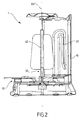
- the figures 1 and 2 represent a first embodiment of a domestic vertical cooking appliance 1 according to the present invention.
- This apparatus suitable for vertical cooking of foods such as kebab meat, fish, cheese or vegetables, mainly comprises an outer protective frame 10 describing a vertical portion of the cylinder when the apparatus is laid flat for its use, typically between 90 ° and 180 °, an electrical resistance 20 conforming to the inner shape of the frame and extending vertically along the latter, a lower plate 30 rotatable about an axis XX 'parallel to the resistor 20 and a tubular cooking support 40, and means 50 for fixing the cooking support 40 to the lower plate 30.
- the resistance describes substantially the same arc as the outer frame, that is to say between 90 ° and 180 °, and is in the form of one or more coils.
- the food 45 to be grilled is pre-fitted on the vertical cooking support 40 forming a spindle, the unitary unit thus created forming a refill sold preferably under vacuum, including support, in a distribution network type supermarket or hyper market.
- the customer having the apparatus must then just position and fix the support 40 on the plate 30 with the destructible attachment means 50 provided for this purpose in order to eat the food 45 and grilling / cooking as it would be done in a restaurant usually selling this type of product.
- This device is not only user-friendly but it also provides a significant comfort of consumption because of its very hygienic side.
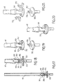
- the support 40 can never be reused because the fact of detaching it from the plateau irreversibly destroying the fastening means 50, as described below in connection with the Figures 3 to 37 .
- the destructible fixing means 50 comprise at least one breakable zone adapted to definitively separate the latter during the first separation between the baking support and the lower plate, for example by twisting, pulling, compressing, bending or any other force.
- the rod 51 has a breakable zone 60 for permanently separating the articulated lugs 53 from a portion of the core 52 of the rod 51, for example by twisting and / or pulling the rod 51 of the cooking support 40 with respect to the sleeve 56 of the lower plate 30.
- the core 52 of the rod 51 breaks substantially at the area of attachment / articulation of the legs 53 on said core 52, that is to say at the level of the breakable zone 60 , the sleeve 55 remaining intact to receive a new "refill", that is to say a new support lined with a food to grill.
- the same cooking medium 30 is therefore never used more than once.
- the collar 151 has a breakable zone 153, in the form of a cut-off sequence made in the material in the manner of a dotted line, and comprises a tear-off tab 154 making it possible to definitively separate the cooking support 40 from the lower plate 30 by breaking said strips 152 along the breakable zone 153 by pulling on the tab 154.
- the cooking support 40 becomes unusable after its first use once the flange 151 has been torn off ( figure 11 ).
- the Figures 12 to 16 illustrate a third embodiment of the destructible fastening means 50.
- These means more specifically comprise a tubular sleeve 251 bonded, for example by screwing, to a hollow end fixing the cooking support 40 internally provided with a tapping.
- This sleeve 251 is provided with two elastic parallel tabs 252 each having at least one breakable zone 253.
- the destructible fastening means 50 also comprise a fastening head 255 integral with the lower plate 30 and having a protuberance of 256 complementary shape of the defined space between the tabs 252.
- the head 255 also has parallel bearing surfaces 257 cooperating with internal locking surfaces 54 provided on the tabs 252 so as to cooperate with the latter to ensure the connection of the cooking support to the lower plate for use of the device.
- the tabs 252 surround the fastening head 255 and hang in axial translation and in rotation thanks to the protuberance 256 and the surfaces 254 and 257.
- the support 40 is integral with the plate 30 and can be rotated by the latter to grill the food 45.
- the user breaks the tabs 252 at their respective rupture zones 253, either by turning the support 40 sufficiently with respect to the plate 30, or by tilting the support by inclining it strongly with respect to the axis XX .
- the cooking support 40 is permanently disconnected from the lower plate 30 and can not be reused.
- the head 255 remains intact to accommodate a new support 40 with its food fitted.
- FIGS 17 to 21 illustrate a fourth embodiment of the destructible fastening means 50 fairly close to that of Figures 12 to 16 .
- these means comprise more precisely a sleeve 351 mounted by crimping at the end of the cooking support 40 and provided with two parallel elastic tabs 352 each having at least one breakable zone 353, preferably three breakable zones per leg 352 in the present case.
- the destructible fixing means 50 also comprise a fixing head 355 integral with the lower plate 30 and having a protrusion 356 of complementary shape of the space defined between the tabs 352 so as to cooperate with the latter to ensure the connection of the support of cooking 40 to the lower tray 30 for use of the apparatus
- the tabs 352 surround the fixing head 355 and lock in axial translation and in rotation thanks to the protuberance 356 and to the flat surfaces 354 and 357 of which the inside of the tabs 352 and the outside of the head 355 are respectively provided.
- the support 40 is secured to the plate 30 and can be rotated by the latter to grill the food 45.
- the user breaks the tabs 352 at their respective breaking zones 353, either by turning the support 40 sufficiently with respect to the plate 30, or by tilting the support 30, as previously described.
- the cooking support 40 is disengaged from final way of the lower plate 30 and can not be reused.
- the head 355 remains intact to accommodate a new support 40 with its food fitted.
- the Figures 22 to 26 illustrate a fifth embodiment of the destructible fastening means 50.
- These means consist of a hollow cylindrical collar 451 disposed at one end of attachment of the cooking support 40 and in the extension thereof, said collar 451 comprising a succession of lamellae radially elastic members 452 disposed along its circumference, each lamella 452 having, on either side, a breakable zone 453 making it possible to connect it to two adjacent fixed legs 454.
- the fastening means also comprise a fastening head 455 bound to the lower plate 30, said head having a curved shape 456 having an outer diameter substantially equal to the inner diameter of the collar 451 when the lamellae 452 are spaced apart, and a groove 457 cooperating with the free ends of the lamellae 452 to ensure the connection from the cooking support 40 to the lower tray 30 for use of the apparatus.
- the lamellae 452 surround the fixing head 455 and hang in axial translation and in rotation thanks to the protuberance of the groove 457.
- the support 40 is integral with the plate 30 and can be rotated by the latter for grill food 45.
- the user breaks the lamellae 452 at their breaking zones 453, for example by tilting the support 30.
- the cooking support 40 is permanently disconnected from the lower plate 30 and can not be reused.
- the head 455 remains intact to accommodate a new support 40 with its food fitted.
- the lamellae 552 for example two lamellae opposed to the four present, comprise a breakable zone 553 making it possible to definitively dissolve the cooking support 40 from the lower plate 30 by breaking said lamellae along the breakable zone 553, for example by traction or bending.
- the support 40 in the position illustrated by the Figures 27 and 29 , the support 40 is fixed on the lower plate 30 while in the position illustrated by the figure 30 , the strips 552 are irreversibly detached from the flange 551 so that the support 40 can not be used again.
- the user must therefore buy a new refill to install on the plate 30 as long as the head 555 remains intact after breaking the scored area 553.
- all the blades 552 are equipped with a breakable zone 553 so that they break together during the first separation of the support and the plate.
- FIGS. 34 to 37 illustrate an eighth embodiment of the destructible fixing means 50.
- These means consist of a ring 651 linked to one end of the cooking support 40 and having an internal thread 652, and a fixing head 655 linked to the lower plate 30 and comprising a thread 656 cooperating with the thread 652 of the ring 651 to ensure the connection of the cooking support 40 to the lower plate 30 for the use of the apparatus.
- the ring 651 has a breakable zone 653 all around its upper periphery and comprises a pull tab 654 for permanently dissociating the cooking support 40 from the lower plate 30 by tearing said ring along the breakable zone 653 by pulling on said tongue 654, as illustrated in FIG. figure 37 , thereby rendering the support 40 unusable after its first use.
- the lower plate 30 is also movable in translation relative to the resistance 20 to bring it closer to or away from the latter, before cooking and / or during cooking of the food.
- it can include a manual or motorized system.
- the apparatus 1 further comprises an upper rotary plate 70 connected to the cooking support 40 and mobile in rotation simultaneously with the latter and the lower plate 30.
- This upper plate 70 is particularly well adapted to receive vertical skewers 71 connected to suspension hooks 72 themselves mounted respectively on rotary turnstiles 73, for example four in number.
- the rotation of the support 40 on its axis causes the rotation of the upper plate 70 simultaneously with the rotation of each turnstile 73 which rotates the skewer 72 vertically on itself to grill each part of the food in an optimized manner.
- Food may be of any type, a mixture of meat and vegetables, poultry and vegetables, fish and vegetables, cheese alone or accompanied, provided that they are pre-loaded on a new support respecting the required hygiene conditions, said support and the food being sold unitarily, for example under vacuum, to constitute a "family" single-use refill.
Landscapes
- Engineering & Computer Science (AREA)
- Food Science & Technology (AREA)
- Baking, Grill, Roasting (AREA)
- Food-Manufacturing Devices (AREA)
Claims (14)
- Haushaltsgerät (1) zum vertikalen Garen eines Nahrungsmittels, zum Beispiel Kebabfleisch, mit- einem äußeren Schutzgehäuse (10),- einer Wärmequelle (20), die sich in vertikaler Richtung entlang und im Inneren des Schutzgehäuses erstreckt, wenn das Gerät flach auf eine Arbeitsfläche gestellt wird,- einer unteren Platte (30), die zumindest in Drehung entlang einer Achse beweglich ist, die zu der Wärmequelle parallel ist,- einer vertikalen rohrförmigen Garhalterung (40), um die herum ein zu erwärmendes/garendes/grillendes Nahrungsmittel (45) platziert ist, wobei die Garhalterung (40) und die untere Platte (30) jeweils Befestigungsmittel (50) aufweisen,dadurch gekennzeichnet, dass die Befestigungsmittel (50) dafür geeignet sind, nach ihrer ersten Verwendung beim Lösen der Halterung und der Platte irreversibel zerstört zu werden, derart, dass die Garhalterung (40) zur einmaligen Verwendung bestimmt ist und nur ein einziges Mal auf der unteren Platte (30) angeordnet werden kann.
- Gargerät nach Anspruch 1, dadurch gekennzeichnet, dass die Garhalterung (40) von einem zylindrischen Rohr gebildet ist, das eine Drehspindel bildet.
- Gargerät nach Anspruch 1 oder 2, dadurch gekennzeichnet, dass die Befestigungsmittel (50) mindestens eine durchtrennbare Zone (60; 153; 253; 353; 453; 553; 653) aufweisen, die dafür geeignet ist, mindestens bestimmte der Befestigungsmittel (50) beim ersten Lösen, zum Beispiel durch Verdrehen, Ziehen, Zusammendrücken, Biegen oder jede andere Kraft, zwischen der Garhalterung (40) und der unteren Platte (30) auf endgültige Weise zu trennen.
- Gargerät nach Anspruch 3, dadurch gekennzeichnet, dass die Befestigungsmittel (50) gebildet sind von- einer Stange (51), die mit einem Befestigungsende der Garhalterung (40) und in der axialen Verlängerung Letzterer verbunden ist, wobei die Stange (51) einen mittleren Kern (52) und zwei parallele Laschen (53) aufweist, die an dem freien Ende (52a) des Kerns (52) angelenkt sind, um sich von diesem letzten weg oder zu diesem hin bewegen zu können und ein Rohr zu bilden, wobei jede Lasche (53) mit radialen Ausstülpungen zum Einrasten (54) versehen ist,- einer Aufnahmehülse (55), die mit der unteren Platte verbunden ist und einen Schlitz (56) und zwei im Wesentlichen in radialer Richtung elastische Schenkel (57) aufweist, die eine Öffnung für die Aufnahme (58) des Kerns (52) und der Laschen (53) der Stange (51) festlegen, wobei die Schenkel innen eine kreisförmige Rille (59) aufweisen, die mit den Ausstülpungen (54) der Laschen (53) zusammenwirkt, um die Verbindung der Garhalterung (40) mit der unteren Platte (30) bei der Verwendung des Geräts zu bewirken, und- wobei die Stange (51) eine durchtrennbare Zone (60) aufweist, die es ermöglicht, die angelenkten Laschen (53) von einem Teil des Kerns (52) der Stange (51) auf endgültige Weise zu lösen, zum Beispiel durch Verdrehen und/oder Ziehen der Stange (51) der Garhalterung (40) relativ zu der Hülse (55) der unteren Platte (30).
- Gargerät nach Anspruch 3, dadurch gekennzeichnet, dass die Befestigungsmittel (50) gebildet sind von- einem hohlen, ringförmigen Kragen (151), der an einem Befestigungsende der Garhalterung (40) und in der axialen Verlängerung Letzterer angeordnet ist, wobei der Kragen (151) eine Folge von Lamellen (152) aufweist, die in radialer Richtung elastisch entlang seines Umfangs angeordnet sind,- einem Befestigungskopf (155), der mit der unteren Platte (30) verbunden ist, wobei der Kopf (155) eine gewölbte Form (156) mit einem Außendurchmesser aufweist, der im Wesentlichen gleich dem Innendurchmesser des Kragens (151) ist, wenn die Lamellen (152) aufgespreizt sind, derart, dass er mit diesen letzten zusammenwirkt, um die Verbindung der Garhalterung (40) mit der unteren Platte (30) bei der Verwendung des Geräts zu bewirken, und- wobei der Kragen (151) eine durchtrennbare Zone (153) aufweist und eine Aufreisszunge (154) aufweist, die es ermöglicht, die Garhalterung (40) auf endgültige Weise von der unteren Platte (30) durch Durchbrechen der Lamellen (152) entlang der durchtrennbaren Zone (153) zu lösen, indem an der Zunge (154) gezogen wird.
- Gargerät nach Anspruch 3, dadurch gekennzeichnet, dass die Befestigungsmittel (50) gebildet sind von- einer rohrförmigen Hülse (251; 351), die, zum Beispiel durch Verschrauben oder Aufquetschen, mit einem Befestigungsende der Garhalterung (40) verbunden ist und zwei parallele elastische Laschen (252; 352) aufweist, die zwischen einander einen Spalt begrenzen,- einem Befestigungskopf (255; 355), der mit der unteren Platte (30) verbunden ist und eine Ausstülpung (256; 356) aufweist, deren Form zu dem zwischen den Laschen (252; 352) gebildeten Spalt komplementär ist, derart, dass sie mit diesem zusammenwirkt, um die Verbindung der Garhalterung (40) mit der unteren Platte (30) bei der Verwendung des Geräts zu bewirken, und- wobei jede Lasche (252; 352) mindestens eine durchtrennbare Zone (253; 353) aufweist, die es ermöglicht, die Garhalterung (40) auf endgültige Weise von der unteren Platte (30) durch Durchbrechen der Laschen (252; 352) entlang der durchtrennbaren Zone (253; 353) zu lösen, zum Beispiel durch Verdrehen der rohrförmigen Hülse (251; 351) relativ zu dem Befestigungskopf (256; 356).
- Gargerät nach Anspruch 3, dadurch gekennzeichnet, dass die Befestigungsmittel (50) gebildet sind von- einem hohlen, zylindrischen Kragen (451), der an einem Befestigungsende der Garhalterung (40) und in der Verlängerung Letzterer angeordnet ist, wobei der Kragen (451) eine Folge von Lamellen (452) aufweist, die in radialer Richtung elastisch entlang seines Umfangs angeordnet sind,- einem Befestigungskopf (455), der mit der unteren Platte (30) verbunden ist, wobei der Kopf (455) eine gewölbte Form (456) mit einem Außendurchmesser aufweist, der im Wesentlichen gleich dem Innendurchmesser des Kragens (451) ist, wenn die Lamellen (452) aufgespreizt sind, derart, dass er mit Letzteren zusammenwirkt, um die Verbindung der Garhalterung (40) mit der unteren Platte (30) bei der Verwendung des Geräts zu bewirken, und- wobei jede Lamelle (452) des Kragens (451) zwischen zwei festen Laschen (454) montiert ist, im Bereich einer durchtrennbaren Zone (453), die es ermöglicht, die Garhalterung (40) auf endgültige Weise von der unteren Platte (30) durch Durchbrechen der Lamellen (452) entlang der durchtrennbaren Zone (453) zu lösen, zum Beispiel durch Ziehen oder Biegen.
- Gargerät nach Anspruch 3, dadurch gekennzeichnet, dass die Befestigungsmittel (50) gebildet sind von- einem hohlen, zylindrischen Kragen (551), der an einem Befestigungsende der Garhalterung (40) und in der Verlängerung Letzterer angeordnet ist, wobei der Kragen (551) eine Folge von Lamellen (552) aufweist, die in radialer Richtung elastisch entlang seines Umfangs angeordnet sind, und, innen, ein Gewinde (554) aufweist,- einem Befestigungskopf (555), der mit der unteren Platte (30) verbunden ist, wobei der Kopf (555) einen Schraubengang (556) aufweist, der mit dem Innengewinde (554) des Kragens (551) zusammenwirkt, um die Verbindung der Garhalterung (40) mit der unteren Platte (30) bei der Verwendung des Geräts sicherzustellen, und- wobei bestimmte der Lamellen (552) eine durchtrennbare Zone (553) aufweisen, die es ermöglicht, die Garhalterung (40) auf endgültige Weise von der unteren Platte (30) durch Durchbrechen der Lamellen (552) entlang der durchtrennbaren Zone (553) zu lösen, zum Beispiel durch Ziehen oder Biegen.
- Gargerät nach Anspruch 3, dadurch gekennzeichnet, dass die Befestigungsmittel gebildet sind von- einem Ring (651), der mit einem Befestigungsende der Garhalterung (40) verbunden ist und ein Innengewinde (652) aufweist,- einem Befestigungskopf (655), der mit der unteren Platte (30) verbunden ist und einen Schraubengang (656) aufweist, der mit dem Innengewinde (652) des Rings (651) zusammenwirkt, um die Verbindung der Garhalterung (40) mit der unteren Platte (30) bei der Verwendung des Geräts zu bewirken, und- wobei der Ring (651) eine durchtrennbare Zone (653) aufweist und eine Aufreisszunge (654) aufweist, die es ermöglicht, die Garhalterung (40) auf endgültige Weise von der unteren Platte (30) durch Aufreissen des Rings (651) entlang der durchtrennbaren Zone (653) zu lösen, indem an der Zunge (654) gezogen wird.
- Gargerät nach einem der vorhergehenden Ansprüche, dadurch gekennzeichnet, dass die untere Platte (30) auch relativ zu der Wärmequelle (20) in Translation beweglich ist, um sie vor dem Garen und/oder während des Garens des Nahrungsmittels (45) zu Letzterer hin oder von ihr weg zu bewegen.
- Gargerät nach einem der vorhergehenden Ansprüche, dadurch gekennzeichnet, dass es ferner eine obere Drehplatte (70) aufweist, die mit der Garhalterung (40) verbunden ist und gleichzeitig mit Letzterer und der unteren Platte (30) drehbeweglich ist, wobei die obere Platte für die Aufnahme von vertikalen Spießen (71) geeignet ist.
- Gerät nach einem der vorhergehenden Ansprüche, dadurch gekennzeichnet, dass die Wärmequelle (20) ein gekrümmter elektrischer Widerstand ist, der mindestens einen Bogen von 90° um die Garhalterung (40) beschreibt und eine Leistung hat, die je nach Typ des zu erwärmenden/garenden/grillenden Nahrungsmittels veränderbar ist.
- Rohrförmige Halterung (40) für ein Gerät zum vertikalen Garen (1), insbesondere nach einem der vorhergehenden Ansprüche, die Mittel zum Befestigen (50) des Gargeräts an einer Platte (30) aufweist, dadurch gekennzeichnet, dass die Befestigungsmittel (50) nach Erstverwendung zerstörbar sind, wodurch sie die Halterung (40) ein einziges Mal verwendbar und nicht erneut auf der Platte (30) positionierbar machen.
- Halterung nach Anspruch 13, dadurch gekennzeichnet, dass sie ein unter Vakuum platziertes Nahrungsmittel (45), insbesondere Kebabfleisch, Geflügel, Fisch, Gemüse oder auch Käse, umgibt, derart, dass sie eine verzehrbare Nachfüllung bildet, die gebrauchsfertig ist und zum Beispiel mehrere Hundert Gramm wiegt.
Applications Claiming Priority (2)
| Application Number | Priority Date | Filing Date | Title |
|---|---|---|---|
| FR1051022A FR2956311B1 (fr) | 2010-02-15 | 2010-02-15 | Appareil domestique pour la cuisson verticale d'un aliment, par exemple de la viande pour kebab |
| PCT/FR2011/050281 WO2011098733A1 (fr) | 2010-02-15 | 2011-02-10 | Appareil domestique pour la cuisson verticale d'un aliment, par exemple de la viande pour kebab |
Publications (2)
| Publication Number | Publication Date |
|---|---|
| EP2536320A1 EP2536320A1 (de) | 2012-12-26 |
| EP2536320B1 true EP2536320B1 (de) | 2014-07-02 |
Family
ID=42344397
Family Applications (1)
| Application Number | Title | Priority Date | Filing Date |
|---|---|---|---|
| EP11708545.6A Active EP2536320B1 (de) | 2010-02-15 | 2011-02-10 | Haushaltsgerät für vertikales garen von speisen, zum beispiel kebabfleisch |
Country Status (4)
| Country | Link |
|---|---|
| EP (1) | EP2536320B1 (de) |
| ES (1) | ES2511091T3 (de) |
| FR (1) | FR2956311B1 (de) |
| WO (1) | WO2011098733A1 (de) |
Families Citing this family (1)
| Publication number | Priority date | Publication date | Assignee | Title |
|---|---|---|---|---|
| FR3063214B1 (fr) * | 2017-02-27 | 2019-03-29 | L'eclipse | Appareil domestique pour la cuisson verticale d'un aliment |
Family Cites Families (2)
| Publication number | Priority date | Publication date | Assignee | Title |
|---|---|---|---|---|
| DE29615432U1 (de) * | 1996-09-05 | 1996-10-17 | Yedek, Fuat, 89547 Gerstetten | Vorrichtung zum Grillen von Lebensmitteln |
| US6047633A (en) * | 1998-06-23 | 2000-04-11 | Khaytman; Yefim B. | Shish kebab rotisserie |
-
2010
- 2010-02-15 FR FR1051022A patent/FR2956311B1/fr active Active
-
2011
- 2011-02-10 WO PCT/FR2011/050281 patent/WO2011098733A1/fr not_active Ceased
- 2011-02-10 EP EP11708545.6A patent/EP2536320B1/de active Active
- 2011-02-10 ES ES11708545.6T patent/ES2511091T3/es active Active
Also Published As
| Publication number | Publication date |
|---|---|
| WO2011098733A1 (fr) | 2011-08-18 |
| FR2956311A1 (fr) | 2011-08-19 |
| FR2956311B1 (fr) | 2012-03-16 |
| ES2511091T3 (es) | 2014-10-22 |
| EP2536320A1 (de) | 2012-12-26 |
Similar Documents
| Publication | Publication Date | Title |
|---|---|---|
| CA2821569C (fr) | Appareil de cuisson d'aliments avec pale de remuage | |
| US8408120B2 (en) | Vertical rotisserie broiler | |
| EP1514804A1 (de) | Verpackung für Lebensmittel zum Kochen der Lebenmittel mit Dampf | |
| US5649728A (en) | Tong-like eating utensil | |
| EP3087885B1 (de) | Elektrohaushaltsgerät zur essenszubereitung | |
| EP0210106B1 (de) | Zubereitungsvorrichtung für essbare Produkte, welche zusammen mit Brot gegessen werden | |
| EP2536320B1 (de) | Haushaltsgerät für vertikales garen von speisen, zum beispiel kebabfleisch | |
| US20050268794A1 (en) | Spool rotisserie system | |
| US4781109A (en) | Apparatus for heating and displaying food products on a stick | |
| US20210315418A1 (en) | System and method for improving the cooking of foodstuff for rotisserie grilling applications | |
| MX2013014317A (es) | Dispositivo de suspension y condimentacion. | |
| FR2786382A1 (fr) | Appareil electrodomestique multifonctions | |
| US20130295238A1 (en) | Packaging for Selling and Preparing a Combined Food Product | |
| FR3080268A1 (fr) | Dispositif de brochette pour rotir ou griller des aliments | |
| FR3063214A1 (fr) | Appareil domestique pour la cuisson verticale d'un aliment | |
| US9635977B2 (en) | Device and system for cooking bacon wrapped foods | |
| JP7627823B2 (ja) | 串料理調理器具及び串料理の製造方法 | |
| KR102250910B1 (ko) | 조립식 석쇠 | |
| US2285271A (en) | Broiler | |
| KR102203805B1 (ko) | 조립식 석쇠 | |
| FR2841115A1 (fr) | Pince retourneuse pour grillade | |
| FR2724305A1 (fr) | Dispositif de support de breche a viandes | |
| WO2014083269A1 (fr) | Dispositif d'emballage et de cuisson pour aliments | |
| WO2024069569A1 (fr) | Ustensile de cuisine pour la réalisation de préparations culinaires avec des morceaux | |
| WO1999004675A1 (fr) | Appareil de cuisson de type barbecue |
Legal Events
| Date | Code | Title | Description |
|---|---|---|---|
| PUAI | Public reference made under article 153(3) epc to a published international application that has entered the european phase |
Free format text: ORIGINAL CODE: 0009012 |
|
| 17P | Request for examination filed |
Effective date: 20120716 |
|
| AK | Designated contracting states |
Kind code of ref document: A1 Designated state(s): AL AT BE BG CH CY CZ DE DK EE ES FI FR GB GR HR HU IE IS IT LI LT LU LV MC MK MT NL NO PL PT RO RS SE SI SK SM TR |
|
| DAX | Request for extension of the european patent (deleted) | ||
| GRAP | Despatch of communication of intention to grant a patent |
Free format text: ORIGINAL CODE: EPIDOSNIGR1 |
|
| INTG | Intention to grant announced |
Effective date: 20140314 |
|
| RIN1 | Information on inventor provided before grant (corrected) |
Inventor name: BARRE, PASCAL Inventor name: FORGE, DIDIER Inventor name: OGER, MARC Inventor name: PRIOLLAUD-SAVEY, FRANCOIS |
|
| GRAS | Grant fee paid |
Free format text: ORIGINAL CODE: EPIDOSNIGR3 |
|
| GRAA | (expected) grant |
Free format text: ORIGINAL CODE: 0009210 |
|
| AK | Designated contracting states |
Kind code of ref document: B1 Designated state(s): AL AT BE BG CH CY CZ DE DK EE ES FI FR GB GR HR HU IE IS IT LI LT LU LV MC MK MT NL NO PL PT RO RS SE SI SK SM TR |
|
| REG | Reference to a national code |
Ref country code: GB Ref legal event code: FG4D Free format text: NOT ENGLISH |
|
| REG | Reference to a national code |
Ref country code: CH Ref legal event code: EP Ref country code: AT Ref legal event code: REF Ref document number: 675435 Country of ref document: AT Kind code of ref document: T Effective date: 20140715 |
|
| REG | Reference to a national code |
Ref country code: IE Ref legal event code: FG4D Free format text: LANGUAGE OF EP DOCUMENT: FRENCH |
|
| REG | Reference to a national code |
Ref country code: DE Ref legal event code: R096 Ref document number: 602011008105 Country of ref document: DE Effective date: 20140814 |
|
| REG | Reference to a national code |
Ref country code: ES Ref legal event code: FG2A Ref document number: 2511091 Country of ref document: ES Kind code of ref document: T3 Effective date: 20141022 |
|
| REG | Reference to a national code |
Ref country code: AT Ref legal event code: MK05 Ref document number: 675435 Country of ref document: AT Kind code of ref document: T Effective date: 20140702 |
|
| REG | Reference to a national code |
Ref country code: NL Ref legal event code: VDEP Effective date: 20140702 |
|
| REG | Reference to a national code |
Ref country code: LT Ref legal event code: MG4D |
|
| PG25 | Lapsed in a contracting state [announced via postgrant information from national office to epo] |
Ref country code: FI Free format text: LAPSE BECAUSE OF FAILURE TO SUBMIT A TRANSLATION OF THE DESCRIPTION OR TO PAY THE FEE WITHIN THE PRESCRIBED TIME-LIMIT Effective date: 20140702 Ref country code: BG Free format text: LAPSE BECAUSE OF FAILURE TO SUBMIT A TRANSLATION OF THE DESCRIPTION OR TO PAY THE FEE WITHIN THE PRESCRIBED TIME-LIMIT Effective date: 20141002 Ref country code: PT Free format text: LAPSE BECAUSE OF FAILURE TO SUBMIT A TRANSLATION OF THE DESCRIPTION OR TO PAY THE FEE WITHIN THE PRESCRIBED TIME-LIMIT Effective date: 20141103 Ref country code: SE Free format text: LAPSE BECAUSE OF FAILURE TO SUBMIT A TRANSLATION OF THE DESCRIPTION OR TO PAY THE FEE WITHIN THE PRESCRIBED TIME-LIMIT Effective date: 20140702 Ref country code: CZ Free format text: LAPSE BECAUSE OF FAILURE TO SUBMIT A TRANSLATION OF THE DESCRIPTION OR TO PAY THE FEE WITHIN THE PRESCRIBED TIME-LIMIT Effective date: 20140702 Ref country code: LT Free format text: LAPSE BECAUSE OF FAILURE TO SUBMIT A TRANSLATION OF THE DESCRIPTION OR TO PAY THE FEE WITHIN THE PRESCRIBED TIME-LIMIT Effective date: 20140702 Ref country code: GR Free format text: LAPSE BECAUSE OF FAILURE TO SUBMIT A TRANSLATION OF THE DESCRIPTION OR TO PAY THE FEE WITHIN THE PRESCRIBED TIME-LIMIT Effective date: 20141003 Ref country code: NO Free format text: LAPSE BECAUSE OF FAILURE TO SUBMIT A TRANSLATION OF THE DESCRIPTION OR TO PAY THE FEE WITHIN THE PRESCRIBED TIME-LIMIT Effective date: 20141002 |
|
| PG25 | Lapsed in a contracting state [announced via postgrant information from national office to epo] |
Ref country code: CY Free format text: LAPSE BECAUSE OF FAILURE TO SUBMIT A TRANSLATION OF THE DESCRIPTION OR TO PAY THE FEE WITHIN THE PRESCRIBED TIME-LIMIT Effective date: 20140702 Ref country code: HR Free format text: LAPSE BECAUSE OF FAILURE TO SUBMIT A TRANSLATION OF THE DESCRIPTION OR TO PAY THE FEE WITHIN THE PRESCRIBED TIME-LIMIT Effective date: 20140702 Ref country code: RS Free format text: LAPSE BECAUSE OF FAILURE TO SUBMIT A TRANSLATION OF THE DESCRIPTION OR TO PAY THE FEE WITHIN THE PRESCRIBED TIME-LIMIT Effective date: 20140702 Ref country code: AT Free format text: LAPSE BECAUSE OF FAILURE TO SUBMIT A TRANSLATION OF THE DESCRIPTION OR TO PAY THE FEE WITHIN THE PRESCRIBED TIME-LIMIT Effective date: 20140702 Ref country code: LV Free format text: LAPSE BECAUSE OF FAILURE TO SUBMIT A TRANSLATION OF THE DESCRIPTION OR TO PAY THE FEE WITHIN THE PRESCRIBED TIME-LIMIT Effective date: 20140702 Ref country code: PL Free format text: LAPSE BECAUSE OF FAILURE TO SUBMIT A TRANSLATION OF THE DESCRIPTION OR TO PAY THE FEE WITHIN THE PRESCRIBED TIME-LIMIT Effective date: 20140702 Ref country code: IS Free format text: LAPSE BECAUSE OF FAILURE TO SUBMIT A TRANSLATION OF THE DESCRIPTION OR TO PAY THE FEE WITHIN THE PRESCRIBED TIME-LIMIT Effective date: 20141102 Ref country code: NL Free format text: LAPSE BECAUSE OF FAILURE TO SUBMIT A TRANSLATION OF THE DESCRIPTION OR TO PAY THE FEE WITHIN THE PRESCRIBED TIME-LIMIT Effective date: 20140702 |
|
| REG | Reference to a national code |
Ref country code: DE Ref legal event code: R097 Ref document number: 602011008105 Country of ref document: DE |
|
| PG25 | Lapsed in a contracting state [announced via postgrant information from national office to epo] |
Ref country code: IT Free format text: LAPSE BECAUSE OF FAILURE TO SUBMIT A TRANSLATION OF THE DESCRIPTION OR TO PAY THE FEE WITHIN THE PRESCRIBED TIME-LIMIT Effective date: 20140702 Ref country code: RO Free format text: LAPSE BECAUSE OF FAILURE TO SUBMIT A TRANSLATION OF THE DESCRIPTION OR TO PAY THE FEE WITHIN THE PRESCRIBED TIME-LIMIT Effective date: 20140702 Ref country code: DK Free format text: LAPSE BECAUSE OF FAILURE TO SUBMIT A TRANSLATION OF THE DESCRIPTION OR TO PAY THE FEE WITHIN THE PRESCRIBED TIME-LIMIT Effective date: 20140702 Ref country code: EE Free format text: LAPSE BECAUSE OF FAILURE TO SUBMIT A TRANSLATION OF THE DESCRIPTION OR TO PAY THE FEE WITHIN THE PRESCRIBED TIME-LIMIT Effective date: 20140702 Ref country code: SK Free format text: LAPSE BECAUSE OF FAILURE TO SUBMIT A TRANSLATION OF THE DESCRIPTION OR TO PAY THE FEE WITHIN THE PRESCRIBED TIME-LIMIT Effective date: 20140702 |
|
| PLBE | No opposition filed within time limit |
Free format text: ORIGINAL CODE: 0009261 |
|
| STAA | Information on the status of an ep patent application or granted ep patent |
Free format text: STATUS: NO OPPOSITION FILED WITHIN TIME LIMIT |
|
| 26N | No opposition filed |
Effective date: 20150407 |
|
| PG25 | Lapsed in a contracting state [announced via postgrant information from national office to epo] |
Ref country code: LU Free format text: LAPSE BECAUSE OF FAILURE TO SUBMIT A TRANSLATION OF THE DESCRIPTION OR TO PAY THE FEE WITHIN THE PRESCRIBED TIME-LIMIT Effective date: 20150210 |
|
| REG | Reference to a national code |
Ref country code: CH Ref legal event code: PL |
|
| PG25 | Lapsed in a contracting state [announced via postgrant information from national office to epo] |
Ref country code: CH Free format text: LAPSE BECAUSE OF NON-PAYMENT OF DUE FEES Effective date: 20150228 Ref country code: LI Free format text: LAPSE BECAUSE OF NON-PAYMENT OF DUE FEES Effective date: 20150228 Ref country code: MC Free format text: LAPSE BECAUSE OF FAILURE TO SUBMIT A TRANSLATION OF THE DESCRIPTION OR TO PAY THE FEE WITHIN THE PRESCRIBED TIME-LIMIT Effective date: 20140702 |
|
| REG | Reference to a national code |
Ref country code: IE Ref legal event code: MM4A |
|
| PG25 | Lapsed in a contracting state [announced via postgrant information from national office to epo] |
Ref country code: SI Free format text: LAPSE BECAUSE OF FAILURE TO SUBMIT A TRANSLATION OF THE DESCRIPTION OR TO PAY THE FEE WITHIN THE PRESCRIBED TIME-LIMIT Effective date: 20140702 |
|
| PG25 | Lapsed in a contracting state [announced via postgrant information from national office to epo] |
Ref country code: IE Free format text: LAPSE BECAUSE OF NON-PAYMENT OF DUE FEES Effective date: 20150210 |
|
| REG | Reference to a national code |
Ref country code: FR Ref legal event code: PLFP Year of fee payment: 6 |
|
| REG | Reference to a national code |
Ref country code: ES Ref legal event code: FD2A Effective date: 20160329 |
|
| PG25 | Lapsed in a contracting state [announced via postgrant information from national office to epo] |
Ref country code: ES Free format text: LAPSE BECAUSE OF NON-PAYMENT OF DUE FEES Effective date: 20150211 |
|
| PG25 | Lapsed in a contracting state [announced via postgrant information from national office to epo] |
Ref country code: BE Free format text: LAPSE BECAUSE OF NON-PAYMENT OF DUE FEES Effective date: 20160229 |
|
| PGRI | Patent reinstated in contracting state [announced from national office to epo] |
Ref country code: BE Effective date: 20160621 |
|
| PG25 | Lapsed in a contracting state [announced via postgrant information from national office to epo] |
Ref country code: MT Free format text: LAPSE BECAUSE OF FAILURE TO SUBMIT A TRANSLATION OF THE DESCRIPTION OR TO PAY THE FEE WITHIN THE PRESCRIBED TIME-LIMIT Effective date: 20140702 |
|
| REG | Reference to a national code |
Ref country code: FR Ref legal event code: PLFP Year of fee payment: 7 |
|
| PG25 | Lapsed in a contracting state [announced via postgrant information from national office to epo] |
Ref country code: SM Free format text: LAPSE BECAUSE OF FAILURE TO SUBMIT A TRANSLATION OF THE DESCRIPTION OR TO PAY THE FEE WITHIN THE PRESCRIBED TIME-LIMIT Effective date: 20140702 Ref country code: HU Free format text: LAPSE BECAUSE OF FAILURE TO SUBMIT A TRANSLATION OF THE DESCRIPTION OR TO PAY THE FEE WITHIN THE PRESCRIBED TIME-LIMIT; INVALID AB INITIO Effective date: 20110210 |
|
| PG25 | Lapsed in a contracting state [announced via postgrant information from national office to epo] |
Ref country code: TR Free format text: LAPSE BECAUSE OF FAILURE TO SUBMIT A TRANSLATION OF THE DESCRIPTION OR TO PAY THE FEE WITHIN THE PRESCRIBED TIME-LIMIT Effective date: 20140702 |
|
| REG | Reference to a national code |
Ref country code: FR Ref legal event code: PLFP Year of fee payment: 8 |
|
| REG | Reference to a national code |
Ref country code: DE Ref legal event code: R082 Ref document number: 602011008105 Country of ref document: DE Representative=s name: MAIWALD GMBH, DE Ref country code: DE Ref legal event code: R082 Ref document number: 602011008105 Country of ref document: DE Representative=s name: MAIWALD PATENTANWALTS- UND RECHTSANWALTSGESELL, DE |
|
| PG25 | Lapsed in a contracting state [announced via postgrant information from national office to epo] |
Ref country code: MK Free format text: LAPSE BECAUSE OF FAILURE TO SUBMIT A TRANSLATION OF THE DESCRIPTION OR TO PAY THE FEE WITHIN THE PRESCRIBED TIME-LIMIT Effective date: 20140702 |
|
| PG25 | Lapsed in a contracting state [announced via postgrant information from national office to epo] |
Ref country code: AL Free format text: LAPSE BECAUSE OF FAILURE TO SUBMIT A TRANSLATION OF THE DESCRIPTION OR TO PAY THE FEE WITHIN THE PRESCRIBED TIME-LIMIT Effective date: 20140702 |
|
| PGFP | Annual fee paid to national office [announced via postgrant information from national office to epo] |
Ref country code: GB Payment date: 20220225 Year of fee payment: 12 |
|
| GBPC | Gb: european patent ceased through non-payment of renewal fee |
Effective date: 20230210 |
|
| PG25 | Lapsed in a contracting state [announced via postgrant information from national office to epo] |
Ref country code: GB Free format text: LAPSE BECAUSE OF NON-PAYMENT OF DUE FEES Effective date: 20230210 |
|
| PG25 | Lapsed in a contracting state [announced via postgrant information from national office to epo] |
Ref country code: GB Free format text: LAPSE BECAUSE OF NON-PAYMENT OF DUE FEES Effective date: 20230210 |
|
| PGFP | Annual fee paid to national office [announced via postgrant information from national office to epo] |
Ref country code: DE Payment date: 20240226 Year of fee payment: 14 |
|
| PGFP | Annual fee paid to national office [announced via postgrant information from national office to epo] |
Ref country code: BE Payment date: 20240226 Year of fee payment: 14 |
|
| PGFP | Annual fee paid to national office [announced via postgrant information from national office to epo] |
Ref country code: FR Payment date: 20250226 Year of fee payment: 15 |
|
| REG | Reference to a national code |
Ref country code: DE Ref legal event code: R119 Ref document number: 602011008105 Country of ref document: DE |
|
| REG | Reference to a national code |
Ref country code: BE Ref legal event code: MM Effective date: 20250228 |
|
| PG25 | Lapsed in a contracting state [announced via postgrant information from national office to epo] |
Ref country code: DE Free format text: LAPSE BECAUSE OF NON-PAYMENT OF DUE FEES Effective date: 20250902 |
|
| PG25 | Lapsed in a contracting state [announced via postgrant information from national office to epo] |
Ref country code: BE Free format text: LAPSE BECAUSE OF NON-PAYMENT OF DUE FEES Effective date: 20250228 |