EP2536342B1 - Intramedulläre vorrichtung - Google Patents
Intramedulläre vorrichtung Download PDFInfo
- Publication number
- EP2536342B1 EP2536342B1 EP11744328.3A EP11744328A EP2536342B1 EP 2536342 B1 EP2536342 B1 EP 2536342B1 EP 11744328 A EP11744328 A EP 11744328A EP 2536342 B1 EP2536342 B1 EP 2536342B1
- Authority
- EP
- European Patent Office
- Prior art keywords
- guide tube
- bone
- intramedullary rod
- patient
- bore
- Prior art date
- Legal status (The legal status is an assumption and is not a legal conclusion. Google has not performed a legal analysis and makes no representation as to the accuracy of the status listed.)
- Not-in-force
Links
- 210000000988 bone and bone Anatomy 0.000 claims description 42
- 230000002093 peripheral effect Effects 0.000 claims 2
- 238000000034 method Methods 0.000 description 5
- 230000035876 healing Effects 0.000 description 4
- 210000003414 extremity Anatomy 0.000 description 2
- 238000003384 imaging method Methods 0.000 description 2
- 238000003780 insertion Methods 0.000 description 2
- 230000037431 insertion Effects 0.000 description 2
- 230000005855 radiation Effects 0.000 description 2
- 210000000689 upper leg Anatomy 0.000 description 2
- 206010073306 Exposure to radiation Diseases 0.000 description 1
- 206010020649 Hyperkeratosis Diseases 0.000 description 1
- 238000010420 art technique Methods 0.000 description 1
- 238000005452 bending Methods 0.000 description 1
- 230000015572 biosynthetic process Effects 0.000 description 1
- 210000001185 bone marrow Anatomy 0.000 description 1
- 238000010276 construction Methods 0.000 description 1
- 238000001514 detection method Methods 0.000 description 1
- 230000000694 effects Effects 0.000 description 1
- 230000000399 orthopedic effect Effects 0.000 description 1
- 230000035515 penetration Effects 0.000 description 1
- 230000037390 scarring Effects 0.000 description 1
- 238000007789 sealing Methods 0.000 description 1
- 239000007787 solid Substances 0.000 description 1
- 210000002303 tibia Anatomy 0.000 description 1
Images


Classifications
-
- A—HUMAN NECESSITIES
- A61—MEDICAL OR VETERINARY SCIENCE; HYGIENE
- A61B—DIAGNOSIS; SURGERY; IDENTIFICATION
- A61B17/00—Surgical instruments, devices or methods
- A61B17/56—Surgical instruments or methods for treatment of bones or joints; Devices specially adapted therefor
- A61B17/58—Surgical instruments or methods for treatment of bones or joints; Devices specially adapted therefor for osteosynthesis, e.g. bone plates, screws or setting implements
- A61B17/68—Internal fixation devices, including fasteners and spinal fixators, even if a part thereof projects from the skin
- A61B17/72—Intramedullary devices, e.g. pins or nails
- A61B17/7233—Intramedullary devices, e.g. pins or nails with special means of locking the nail to the bone
-
- A—HUMAN NECESSITIES
- A61—MEDICAL OR VETERINARY SCIENCE; HYGIENE
- A61B—DIAGNOSIS; SURGERY; IDENTIFICATION
- A61B17/00—Surgical instruments, devices or methods
- A61B17/16—Instruments for performing osteoclasis; Drills or chisels for bones; Trepans
- A61B17/164—Instruments for performing osteoclasis; Drills or chisels for bones; Trepans intramedullary
-
- A—HUMAN NECESSITIES
- A61—MEDICAL OR VETERINARY SCIENCE; HYGIENE
- A61B—DIAGNOSIS; SURGERY; IDENTIFICATION
- A61B17/00—Surgical instruments, devices or methods
- A61B17/16—Instruments for performing osteoclasis; Drills or chisels for bones; Trepans
- A61B17/17—Guides or aligning means for drills, mills, pins or wires
- A61B17/1717—Guides or aligning means for drills, mills, pins or wires for applying intramedullary nails or pins
-
- A—HUMAN NECESSITIES
- A61—MEDICAL OR VETERINARY SCIENCE; HYGIENE
- A61B—DIAGNOSIS; SURGERY; IDENTIFICATION
- A61B17/00—Surgical instruments, devices or methods
- A61B17/56—Surgical instruments or methods for treatment of bones or joints; Devices specially adapted therefor
- A61B17/58—Surgical instruments or methods for treatment of bones or joints; Devices specially adapted therefor for osteosynthesis, e.g. bone plates, screws or setting implements
- A61B17/68—Internal fixation devices, including fasteners and spinal fixators, even if a part thereof projects from the skin
- A61B17/72—Intramedullary devices, e.g. pins or nails
- A61B17/7283—Intramedullary devices, e.g. pins or nails with special cross-section of the nail
Definitions
- This invention relates generally to medical devices and more particularly to systems for introducing an intramedullary rod into a bone of a patient.
- intramedullary rods also referred to as intramedullary nails
- intramedullary nails are used in orthopedics to align and stabilize fractures.
- Such rods are typically inserted into the bone marrow canal or bore in the center of the long bones of the extremities (e.g., the femur or tibia).
- One of the significant advantages of such rods over other methods of fixation is that they share the load with the bone, rather that entirely support the bone. Because of this, patients are able to use the extremity more quickly.
- rods are fixed in position via the use of transversely extending locking screws.
- transversely extending screw-based fixation techniques While generally effective for its purpose, transversely extending screw-based fixation techniques have drawbacks, namely, placement and fixation is relatively difficult and time consuming and as a result the patient will be exposed to larger doses of radiation resulting from the imaging procedure during the rod's placement and fixation. Moreover, the use of transversely extending locking screws places unnecessary stress at the screw contact points.
- US 5 053 035 A discloses a flexible intramedullary fixation rod for an insertion into a medullary canal of a bone, having an elongated core and a plurality of fins radially disposed about the core periphery. The core radius and the fin radius are selected to provide the rod with a specified bending rigidity.
- Another intramedullary fixation is disclosed in US 4 653 487 A , wherein the fixation comprises an elongated rod with outwardly projecting thin fins.
- the subject invention addresses that need by providing an intramedullary device which obviates the need for transversely extending locking screws and their attendant problems.
- the device of this invention enables its placement and fixation to be accomplished in a shorter period of time than with prior art devices.
- the device of this invention exhibits a more even distribution of stress along its length, thereby facilitating faster healing.
- dynamization i.e., the promotion of bone healing in fractures by allowing some movement or compressive loading
- a system according to claim 1 for introducing an intramedullary rod into a longitudinally extending bore in the bone of a patient.
- the system basically comprises a guide tube, a cutter assembly and an intramedullary rod.
- the guide tube is preferably in the form of an elongated tubular member having a central passageway and a plurality of longitudinally extending slots communicating with the central passageway and is arranged to be located within the bore in the bone of the patient to extend therealong.
- the cutter assembly is preferably in the form of a body member having a plurality of blades extending outward therefrom.
- the body member is arranged to be disposed within the central passageway of the guide tube with the plurality of blades extending outward through respective slots in the guide tube.
- the body member is arranged to be moved longitudinally along the guide tube, e.g., driven therealong by a drive screw extending over a longitudinally extending guide-wire, whereupon the blades produce a plurality of longitudinal grooves in the bore of the bone of the patient.
- the intramedullary rod is preferably in the form of an elongated linear member having a plurality of longitudinally extending ribs projecting outward therefrom.
- the intramedullary rod is arranged to be disposed within the central passageway in said guide tube, whereupon its ribs extend through respective ones of the slots in the guide tube for disposition within respective ones of the longitudinal grooves in the bore of the bone of the patient to thereby fix the intramedullary rod therein.
- the system may be used in a method for deploying the medullary rod into the bone of a patient.
- the method basically comprises disposing a guide tube like described above into the bore in the bone of the patient so that it extends therealong.
- a body member of a cutter assembly like that described above, is then introduced within the central passageway of the guide tube so that the plurality of blades extend outward through respective slots in the guide tube and is moved longitudinally along the guide tube, so that the blades produce a plurality of longitudinal grooves in the bore of the bone of the patient.
- an intramedullary rod like that described above, is introduced within the central passageway in the guide tube, whereupon its ribs extend through respective ones of the slots in the guide tube for disposition within respective ones of the longitudinal grooves in the bore of the bone of the patient to thereby fix the intramedullary rod therein.
- a system including a device in the form of a guide tube 24 and an associated intramedullary rod 26 ( Figs. 3 - 7 ) for introduction into a bore in a bone 10, e.g., femur, of a patient.
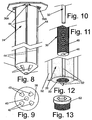
- the system 20 additionally comprises a cutter assembly in the form of a cutter 28 ( Figs. 1 and 12 ), a drive screw 30 ( Figs. 1 and 11 ) and a guide wire 32 ( Fig. 10 ).
- the cutter assembly serves to prepare the bone for the introduction of the guide tube and intramedullary rod therein.
- the cutter assembly is arranged to create a plurality of longitudinally extending grooves in the bore within the bone. Those grooves are arranged to receive respective ones of longitudinally extending ribs (to be described later) of the intramedullary rod so that when the rod is located within the bore the ribs prevent rotation of the intramedullary rod in the patient's bone. This fixes the intramedullary rod in place without the need for conventional screws or other fasteners extending radially through the bone.
- the guide tube 24 is best seen in Fig. 8 and basically comprises an elongated hollow tubular member having circular sidewall 34.
- the proximal end of the guide tube is in the form of a square flange 36 whose corners are cut away diagonally (see Fig. 3 ).
- the distal end 38 of the guide tube is conical and includes a central opening 40 sized to accommodate the guide wire 32 and a plurality of apertures or openings 42 disposed about the central opening 40.
- the guide tube includes a plurality, e.g., four, longitudinally extending slots 44 in its sidewall.
- the slots 44 start at the top surface of the flange 36 and terminate just before the conical distal end 38 of the guide tube.
- a plurality of triangular shaped apertures or holes 36A are provided in pairs in the flange spaced on opposite sides of the entry to each of the slots 44.
- the guide tube 24 is arranged to be introduced into a longitudinal bore 12 ( Fig. 5 ) created in the patient's bone 10. To that end, the interior of the bone is reamed in a conventional manner to create the bore 12. In addition to creating the bore a recess 14 ( Fig. 5 ) is created in the proximal end of the bone 10 at the bore 12 to accommodate the flange 36 of the guide tube 24.
- the guide tube is then forced into the bore 12 by an applicator (not shown) so that the outside surface of the guide tube's sidewall engages the inner surface of the bore in the bone and the flange 36 is within the recess 14.
- the applicator is a conventional device which is modified to include a socket for receipt of the flange 36 of the guide tube.
- the applicator includes a plurality of projections which extend into its socket and which are adapted to be received within correspondingly shaped apertures 36A in the guide tube's flange.
- the guide wire 32 is of a conventional construction, e.g., is a flexible elongated member.
- the drive screw 30 is best seen in Fig. 11 and basically comprises a rod-like member having a central longitudinally extending passageway 46 for receipt of the guide wire 32 so that the guide wire can be extended through it.
- the outer surface of the drive screw includes a helical thread 48.
- the drive screw 30 is arranged to be coupled to a motor (not shown) for rotating it at high rate of speed.
- the cutter 28 is best seen in Figs.
- the cutter 1 and 12 basically comprises an elongated rod-like member whose outside diameter is just slightly less than the inside diameter of the sidewall of the guide tube 24.
- the cutter 28 includes a central passageway 50 which is internally threaded to cooperate with the external threads on the drive screw.
- a plurality, e.g., four, equidistantly spaced, longitudinally extending blades 52 project outward from the cutter. The blades are shaped and sized to fit within respective ones of the slots 44 in the guide tube.
- the cutter assembly is introduced therein.
- the guide wire 32 is extended through the interior of guide tube 24 to pass through its central opening 40.
- the cutter 28 with the drive screw 30 extending therethrough is threaded on the guide wire 32 so that the respective blades 52 of the cutter extend into respective slots 44 in the guide tube.
- the drive screw 30 is than rotated by the motor (not shown) to which it is coupled to move the cutter along the guide wire the distal direction down the interior of the guide tube.
- the slots 44 guide this movement.
- the blades 52 extend beyond the outer periphery of the guide tube.
- the movement of the cutter down the guide tube causes the blades 52 to create respective longitudinally extending grooves 54 ( Fig. 2 ) in the periphery of the bore 12 in the patient's bone.
- the cutter assembly is removed from the guide tube, leaving the guide tube in place, like shown in Fig. 2 .
- the guide tube 24 is now ready to receive the intramedullary nail or rod 26.
- the rod 26 is best shown in Figs. 3 - 7 and basically comprises an elongated cylindrically shaped, solid member whose outside diameter is just slightly less than the inside diameter of the sidewall of the guide tube.
- a plurality, e.g., four, equidistantly spaced, longitudinally extending ribs 56 project outward from the intramedullary rod.
- the ribs 56 are shaped and sized to fit within respective ones of the grooves 54 that were created by the cutter.
- the distal end of the intramedullary rod is best seen in Fig. 6 and is of a dome-like configuration.
- the spikes include a plurality, e.g., four, longitudinally extending barbs or spikes 58 projecting distally parallel to the longitudinal axis of the rod.
- the spikes are arranged to penetrate into the cancellous portion of the bone at the distal end of the bore to seat the rod in place and prevent its longitudinal movement (while permitting some dynamization to be accomplished). To that end, the spikes are oriented so that each passes through a respective aperture 42 in the conical distal end of the guide tube.
- the intramedullary rod 26 is deployed by introducing its distal end into the proximal end of the seated guide tube and with the ribs 56 of the rod aligned with the slots 44 of the guide tube. A force is then applied to the rod to drive it down the interior of the guide tube until its barbs 58 extend out of the apertures 42 in the distal end of the guide tube and into the cancellous portion of the bone.
- the rod 26 is sized so that when in that position its proximal end will be recessed within the guide tube as shown in Fig. 5 .
- the proximal end of the hollow interior passageway of the guide tube includes internal threads 60. These threads are arranged to receive cooperating external threads on a cap 62 ( Fig. 13 ) which is used to seal the rod 26 within the guide tube.
- the shape, size and number of the blades of the cutter as shown herein is merely exemplary and thus other blade arrangements are contemplated.
- the shape of the slots in the guide tube is exemplary.
- other shaped slots can be provided so long as the blades can pass therethrough.
- other means can be used to drive the cutter down the guide tube in lieu of the drive screw, if desired.
- the placement of the ribbed intramedullary rod within the patient bone can be accomplished relatively quickly and easily.
- the ribs of the intramedullary rod create a myriad of continuous contact points along the length of the grooves in the bone in which the ribs are seated. This action serves to prevent relative rotation of the rod within the bone while distributing stress over a much greater area than the prior art.
- the ribs prevent rotation of the rod within the bore, they do not prevent microscopic longitudinal movement, nor do the spikes within the cancellous portion of the bone.
- the intramedullary rod can be moved microscopically longitudinally to effect immediate dynamization and more rapid healing, a feature which is not possible with prior art techniques.
- the subject invention enables the use of imaging radiation to be limited to only in the very beginning of detection of the medulla and insertion of the guide wire in the distal segment, thereby offering the patient less exposure to radiation.
Landscapes
- Health & Medical Sciences (AREA)
- Surgery (AREA)
- Life Sciences & Earth Sciences (AREA)
- Orthopedic Medicine & Surgery (AREA)
- Biomedical Technology (AREA)
- Public Health (AREA)
- Veterinary Medicine (AREA)
- Engineering & Computer Science (AREA)
- Nuclear Medicine, Radiotherapy & Molecular Imaging (AREA)
- Heart & Thoracic Surgery (AREA)
- Medical Informatics (AREA)
- Molecular Biology (AREA)
- Animal Behavior & Ethology (AREA)
- General Health & Medical Sciences (AREA)
- Dentistry (AREA)
- Oral & Maxillofacial Surgery (AREA)
- Neurology (AREA)
- Surgical Instruments (AREA)
Claims (10)
- System (20) zur Einführung eines intramedullären Stabs (26) in ein sich longitudinal erstreckendes Loch (12) im Knochen (10) eines Patienten, wobei das System ein Führungsrohr (24), eine Schneidenanordnung (28) und einen intramedullären Stab (26) umfasst, wobei das Führungsrohr (24) ein längliches röhrenförmiges Element umfasst, das einen zentralen Durchgang und eine Vielzahl von sich longitudinal erstreckenden Schlitzen (44) aufweist, die mit dem zentralen Durchgang in Verbindung stehen, wobei das Führungsrohr (24) angeordnet ist, um in dem Loch (12) in dem Knochen (10) von dem Patienten positioniert zu sein, um sich darin entlang zu erstrecken, wobei die Schneidenanordnung (28) ein Körperelement umfasst, das eine Vielzahl von Klingen (52) aufweist, die sich von diesem auswärts erstrecken, wobei das Körperelement angeordnet ist, um in dem zentralen Durchgang des Führungsrohrs (24) mit der Vielzahl von Klingen (52) sich auswärts durch die entsprechenden Schlitze (44) in dem Führungsrohr (24) erstreckend eingerichtet zu sein, wobei das Körperelement angeordnet ist, longitudinal entlang des Führungsrohrs (24) bewegt zu werden, woraufhin die Klingen (52) eine Vielzahl von longitudinalen Einschnitten in dem Loch (12) des Knochens (10) des Patienten erzeugen, wobei der intramedulläre Stab (26) ein längliches lineares Element umfasst, das eine Vielzahl von sich longitudinal erstreckenden Rippen aufweist, die von diesem auswärts vorragen, wobei der intramedulläre Stab (26) angeordnet ist, in dem zentralen Durchgang in dem Führungsrohr (24) eingerichtet zu sein, woraufhin die Rippen (56) des intramedullären Stabs (26) sich durch jeweils entsprechende Schlitze (44) in dem Führungsrohr (24) zur Anordnung in jeweils entsprechenden longitudinalen Einschnitten (54) in dem Loch (12) des Knochens (10) des Patienten zu erstrecken, um dadurch den intramedullären Stab (26) darin zu fixieren.
- Vorrichtung gemäß Anspruch 1, wobei die Schneidenanordnung (28) zusätzlich eine Antriebsschraube (30) umfasst, um das Körperelement longitudinal entlang des Führungsrohrs (24) zu bewegen.
- Vorrichtung gemäß Anspruch 2, wobei die Antriebsschraube (30) eine zentrale Öffnung (40) enthält, wobei die zentrale Öffnung (40) angeordnet ist, um einen Führungsdraht (32) aufzunehmen, um die Schneidenanordnung (28) durch das Führungsrohr (24) zu führen.
- Vorrichtung gemäß Anspruch 1, wobei das Führungsrohr (24) einen distalen Endbereich enthält, der mindestens eine Apertur darin aufweist, und wobei der intramedulläre Stab (26) ein distales Ende (38) enthält, das mindestens einen Dorn (58) aufweist, der davon für einen Fortsatz durch die mindestens eine Apertur vorragt, um das distale Ende (38) des intramedullären Stabs (26) in dem spongiösen Teilbereich des Knochens (10) des Patienten an das Loch (12) in dem Knochen (10) des Patienten angrenzend zu verankern.
- Vorrichtung gemäß Anspruch 4, wobei das Führungsrohr (24) auch ein proximales Ende enthält, das einen peripheren Flansch (36) aufweist, der sich von dem zentralen Durchgang erstreckt, wobei der Flansch (36) angeordnet ist, in einer Ausnehmung (14) aufgenommen zu werden, die in dem Knochen (10) des Patienten zu der Bohrung (12) darin angrenzend gebildet ist.
- Vorrichtung gemäß Anspruch 5, wobei der Flansch (36) eine Vielzahl von Löchern darin zum Eingriff mit dazugehörigen Elementen eines Applikatorgeräts enthält.
- Vorrichtung gemäß Anspruch 1, wobei das Führungsrohr (24) ein proximales Ende enthält, das einen peripheren Flansch (36) aufweist, der sich von dem zentralen Durchgang erstreckt, wobei der Flansch (36) angeordnet ist, in einer Ausnehmung (14) aufgenommen zu werden, die in dem Knochen (10) des Patienten benachbart zu dem Loch (12) darin gebildet ist.
- Vorrichtung gemäß Anspruch 7, wobei der Flansch (36) auch eine Vielzahl von Löchern in diesem zum Eingriff mit dazugehörigen Elementen einer Applikatorvorrichtung enthält.
- Vorrichtung gemäß Anspruch 5, die zusätzlich eine mit einem Gewinde versehene Kappe (62) umfasst, die angeordnet ist, in dem zentralen Durchgang angrenzend zu dem proximalen Ende davon eingerichtet zu sein, um den Durchgang zu schlieβen, nachdem der intramedulläre Stab (26) in dem Durchgang in dem Führungsrohr (24) angeordnet worden ist.
- Vorrichtung gemäß Anspruch 7, die zusätzlich eine mit einem Gewinde versehene Kappe (62) umfasst, die angeordnet ist, in dem zentralen Durchgang angrenzend zu dem proximalen Ende davon eingerichtet zu sein, um den Durchgang zu schließen, nachdem der intramedulläre Stab (26) in dem Durchgang in dem Führungsrohr (24) angeordnet worden ist.
Applications Claiming Priority (2)
| Application Number | Priority Date | Filing Date | Title |
|---|---|---|---|
| US12/708,952 US8052685B2 (en) | 2010-02-19 | 2010-02-19 | Intramedullary device and method of use |
| PCT/IB2011/000150 WO2011101718A1 (en) | 2010-02-19 | 2011-01-31 | Intramedullary device and method of use |
Publications (3)
| Publication Number | Publication Date |
|---|---|
| EP2536342A1 EP2536342A1 (de) | 2012-12-26 |
| EP2536342A4 EP2536342A4 (de) | 2015-06-24 |
| EP2536342B1 true EP2536342B1 (de) | 2016-08-10 |
Family
ID=44477136
Family Applications (1)
| Application Number | Title | Priority Date | Filing Date |
|---|---|---|---|
| EP11744328.3A Not-in-force EP2536342B1 (de) | 2010-02-19 | 2011-01-31 | Intramedulläre vorrichtung |
Country Status (4)
| Country | Link |
|---|---|
| US (1) | US8052685B2 (de) |
| EP (1) | EP2536342B1 (de) |
| CA (1) | CA2785623C (de) |
| WO (1) | WO2011101718A1 (de) |
Families Citing this family (4)
| Publication number | Priority date | Publication date | Assignee | Title |
|---|---|---|---|---|
| ES2656974T3 (es) * | 2012-01-19 | 2018-03-01 | Stryker European Holdings I, Llc | Manguito para cirugía suprarrotuliana |
| KR102263818B1 (ko) * | 2012-09-14 | 2021-06-15 | 신세스 게엠바하 | 보호 슬리브를 구비한 다중구멍 드릴 슬리브 |
| WO2014043794A1 (en) * | 2012-09-23 | 2014-03-27 | Impetus Innovations, Inc. | A segmental reconstructive intramedullary nail and delivery system |
| JP6371315B2 (ja) * | 2013-02-28 | 2018-08-08 | フェイベル,ジョナサン | 骨要素をリーミングするためのシステム、方法、および装置 |
Family Cites Families (13)
| Publication number | Priority date | Publication date | Assignee | Title |
|---|---|---|---|---|
| US4237875A (en) | 1979-02-23 | 1980-12-09 | Towmotor Corporation | Dynamic intramedullary compression nailing |
| US4653487A (en) * | 1986-01-29 | 1987-03-31 | Maale Gerhard E | Intramedullary rod assembly for cement injection system |
| US5053035A (en) * | 1990-05-24 | 1991-10-01 | Mclaren Alexander C | Flexible intramedullary fixation rod |
| IT1265965B1 (it) | 1994-05-20 | 1996-12-16 | Francesco Saverio Santori | Dispositivo endomillare per la chiodatura di ossa lunghe. |
| US6168599B1 (en) * | 1997-04-14 | 2001-01-02 | Allan S. Frieze | Long bone reamer |
| IT1296954B1 (it) | 1997-12-11 | 1999-08-03 | Ortomedical S P A | Chiodo endomidollare per uso in osteosintesi per il trattamento chirurgico delle fratture diafisometafisarie di femore e di tibia, |
| JP2001258914A (ja) * | 2000-03-22 | 2001-09-25 | Mmt:Kk | 骨髄栓 |
| US6575973B1 (en) | 2000-10-26 | 2003-06-10 | Safedrip Ltd. | Self locking intramedullary nail |
| US6488684B2 (en) | 2001-04-25 | 2002-12-03 | Dale G. Bramlet | Intramedullary nail |
| US7828802B2 (en) * | 2004-01-16 | 2010-11-09 | Expanding Orthopedics, Inc. | Bone fracture treatment devices and methods of their use |
| US20060229617A1 (en) | 2005-02-25 | 2006-10-12 | Orthomechanics Ltd. | Intramedullary devices and methods of deploying the same |
| DE602005011124D1 (de) * | 2005-08-05 | 2009-01-02 | Biedermann Motech Gmbh | Knochenverankerungselement |
| EP2133034B1 (de) | 2008-06-13 | 2011-12-28 | Orthofix S.r.l. | Marknagel zum einsetzen in einen langen Knochen |
-
2010
- 2010-02-19 US US12/708,952 patent/US8052685B2/en not_active Expired - Fee Related
-
2011
- 2011-01-31 EP EP11744328.3A patent/EP2536342B1/de not_active Not-in-force
- 2011-01-31 CA CA 2785623 patent/CA2785623C/en not_active Expired - Fee Related
- 2011-01-31 WO PCT/IB2011/000150 patent/WO2011101718A1/en not_active Ceased
Also Published As
| Publication number | Publication date |
|---|---|
| WO2011101718A1 (en) | 2011-08-25 |
| EP2536342A1 (de) | 2012-12-26 |
| CA2785623C (en) | 2013-07-02 |
| US8052685B2 (en) | 2011-11-08 |
| EP2536342A4 (de) | 2015-06-24 |
| CA2785623A1 (en) | 2011-08-25 |
| US20110208188A1 (en) | 2011-08-25 |
Similar Documents
| Publication | Publication Date | Title |
|---|---|---|
| JP5797654B2 (ja) | 骨粗鬆症骨の上腕骨頭の固定デバイス | |
| US6488684B2 (en) | Intramedullary nail | |
| US9687278B2 (en) | Sleeve for bone fixation device | |
| US8876822B2 (en) | Intramedullary nail system with tang fixation after lock screw placement | |
| JP6811498B2 (ja) | 長骨固定のためのインプラントおよび方法 | |
| US9629670B2 (en) | Intramedullary nails | |
| US8337495B1 (en) | Distal locking intramedullary nail | |
| EP2536342B1 (de) | Intramedulläre vorrichtung | |
| US20150173775A1 (en) | Drill bit and method for preparing a bone for a fixation screw | |
| US12207855B2 (en) | Fixation device and method of using the same | |
| RU2661758C2 (ru) | Винт для блокирующего остеосинтеза переломов костей опорно-двигательного аппарата | |
| US9486259B2 (en) | Bone fixation device | |
| RU86444U1 (ru) | Стержень для чрескостного остеосинтеза | |
| RU26408U1 (ru) | Винт для остеосинтеза |
Legal Events
| Date | Code | Title | Description |
|---|---|---|---|
| PUAI | Public reference made under article 153(3) epc to a published international application that has entered the european phase |
Free format text: ORIGINAL CODE: 0009012 |
|
| 17P | Request for examination filed |
Effective date: 20120725 |
|
| AK | Designated contracting states |
Kind code of ref document: A1 Designated state(s): AL AT BE BG CH CY CZ DE DK EE ES FI FR GB GR HR HU IE IS IT LI LT LU LV MC MK MT NL NO PL PT RO RS SE SI SK SM TR |
|
| DAX | Request for extension of the european patent (deleted) | ||
| RA4 | Supplementary search report drawn up and despatched (corrected) |
Effective date: 20150522 |
|
| RIC1 | Information provided on ipc code assigned before grant |
Ipc: A61B 17/16 20060101ALI20150518BHEP Ipc: A61B 17/72 20060101AFI20150518BHEP Ipc: A61B 17/17 20060101ALI20150518BHEP Ipc: A61F 5/04 20060101ALI20150518BHEP |
|
| GRAP | Despatch of communication of intention to grant a patent |
Free format text: ORIGINAL CODE: EPIDOSNIGR1 |
|
| RIC1 | Information provided on ipc code assigned before grant |
Ipc: A61B 17/17 20060101ALI20160129BHEP Ipc: A61B 17/72 20060101AFI20160129BHEP Ipc: A61B 17/16 20060101ALI20160129BHEP |
|
| INTG | Intention to grant announced |
Effective date: 20160304 |
|
| RAP1 | Party data changed (applicant data changed or rights of an application transferred) |
Owner name: MOHAMED, HOSSAM ABDEL SALAM EL SAYED |
|
| RIN1 | Information on inventor provided before grant (corrected) |
Inventor name: MOHAMED, HOSSAM ABDEL SALAM EL SAYED |
|
| GRAS | Grant fee paid |
Free format text: ORIGINAL CODE: EPIDOSNIGR3 |
|
| GRAA | (expected) grant |
Free format text: ORIGINAL CODE: 0009210 |
|
| AK | Designated contracting states |
Kind code of ref document: B1 Designated state(s): AL AT BE BG CH CY CZ DE DK EE ES FI FR GB GR HR HU IE IS IT LI LT LU LV MC MK MT NL NO PL PT RO RS SE SI SK SM TR |
|
| REG | Reference to a national code |
Ref country code: GB Ref legal event code: FG4D |
|
| REG | Reference to a national code |
Ref country code: CH Ref legal event code: EP Ref country code: AT Ref legal event code: REF Ref document number: 818235 Country of ref document: AT Kind code of ref document: T Effective date: 20160815 |
|
| REG | Reference to a national code |
Ref country code: IE Ref legal event code: FG4D |
|
| REG | Reference to a national code |
Ref country code: DE Ref legal event code: R096 Ref document number: 602011029039 Country of ref document: DE |
|
| REG | Reference to a national code |
Ref country code: LT Ref legal event code: MG4D |
|
| REG | Reference to a national code |
Ref country code: NL Ref legal event code: MP Effective date: 20160810 |
|
| REG | Reference to a national code |
Ref country code: AT Ref legal event code: MK05 Ref document number: 818235 Country of ref document: AT Kind code of ref document: T Effective date: 20160810 |
|
| PG25 | Lapsed in a contracting state [announced via postgrant information from national office to epo] |
Ref country code: FI Free format text: LAPSE BECAUSE OF FAILURE TO SUBMIT A TRANSLATION OF THE DESCRIPTION OR TO PAY THE FEE WITHIN THE PRESCRIBED TIME-LIMIT Effective date: 20160810 Ref country code: NL Free format text: LAPSE BECAUSE OF FAILURE TO SUBMIT A TRANSLATION OF THE DESCRIPTION OR TO PAY THE FEE WITHIN THE PRESCRIBED TIME-LIMIT Effective date: 20160810 Ref country code: RS Free format text: LAPSE BECAUSE OF FAILURE TO SUBMIT A TRANSLATION OF THE DESCRIPTION OR TO PAY THE FEE WITHIN THE PRESCRIBED TIME-LIMIT Effective date: 20160810 Ref country code: LT Free format text: LAPSE BECAUSE OF FAILURE TO SUBMIT A TRANSLATION OF THE DESCRIPTION OR TO PAY THE FEE WITHIN THE PRESCRIBED TIME-LIMIT Effective date: 20160810 Ref country code: IS Free format text: LAPSE BECAUSE OF FAILURE TO SUBMIT A TRANSLATION OF THE DESCRIPTION OR TO PAY THE FEE WITHIN THE PRESCRIBED TIME-LIMIT Effective date: 20161210 Ref country code: NO Free format text: LAPSE BECAUSE OF FAILURE TO SUBMIT A TRANSLATION OF THE DESCRIPTION OR TO PAY THE FEE WITHIN THE PRESCRIBED TIME-LIMIT Effective date: 20161110 Ref country code: HR Free format text: LAPSE BECAUSE OF FAILURE TO SUBMIT A TRANSLATION OF THE DESCRIPTION OR TO PAY THE FEE WITHIN THE PRESCRIBED TIME-LIMIT Effective date: 20160810 Ref country code: IT Free format text: LAPSE BECAUSE OF FAILURE TO SUBMIT A TRANSLATION OF THE DESCRIPTION OR TO PAY THE FEE WITHIN THE PRESCRIBED TIME-LIMIT Effective date: 20160810 |
|
| PG25 | Lapsed in a contracting state [announced via postgrant information from national office to epo] |
Ref country code: AT Free format text: LAPSE BECAUSE OF FAILURE TO SUBMIT A TRANSLATION OF THE DESCRIPTION OR TO PAY THE FEE WITHIN THE PRESCRIBED TIME-LIMIT Effective date: 20160810 Ref country code: PT Free format text: LAPSE BECAUSE OF FAILURE TO SUBMIT A TRANSLATION OF THE DESCRIPTION OR TO PAY THE FEE WITHIN THE PRESCRIBED TIME-LIMIT Effective date: 20161212 Ref country code: SE Free format text: LAPSE BECAUSE OF FAILURE TO SUBMIT A TRANSLATION OF THE DESCRIPTION OR TO PAY THE FEE WITHIN THE PRESCRIBED TIME-LIMIT Effective date: 20160810 Ref country code: LV Free format text: LAPSE BECAUSE OF FAILURE TO SUBMIT A TRANSLATION OF THE DESCRIPTION OR TO PAY THE FEE WITHIN THE PRESCRIBED TIME-LIMIT Effective date: 20160810 Ref country code: GR Free format text: LAPSE BECAUSE OF FAILURE TO SUBMIT A TRANSLATION OF THE DESCRIPTION OR TO PAY THE FEE WITHIN THE PRESCRIBED TIME-LIMIT Effective date: 20161111 Ref country code: ES Free format text: LAPSE BECAUSE OF FAILURE TO SUBMIT A TRANSLATION OF THE DESCRIPTION OR TO PAY THE FEE WITHIN THE PRESCRIBED TIME-LIMIT Effective date: 20160810 Ref country code: PL Free format text: LAPSE BECAUSE OF FAILURE TO SUBMIT A TRANSLATION OF THE DESCRIPTION OR TO PAY THE FEE WITHIN THE PRESCRIBED TIME-LIMIT Effective date: 20160810 |
|
| PG25 | Lapsed in a contracting state [announced via postgrant information from national office to epo] |
Ref country code: EE Free format text: LAPSE BECAUSE OF FAILURE TO SUBMIT A TRANSLATION OF THE DESCRIPTION OR TO PAY THE FEE WITHIN THE PRESCRIBED TIME-LIMIT Effective date: 20160810 Ref country code: RO Free format text: LAPSE BECAUSE OF FAILURE TO SUBMIT A TRANSLATION OF THE DESCRIPTION OR TO PAY THE FEE WITHIN THE PRESCRIBED TIME-LIMIT Effective date: 20160810 |
|
| REG | Reference to a national code |
Ref country code: DE Ref legal event code: R097 Ref document number: 602011029039 Country of ref document: DE |
|
| PG25 | Lapsed in a contracting state [announced via postgrant information from national office to epo] |
Ref country code: BE Free format text: LAPSE BECAUSE OF FAILURE TO SUBMIT A TRANSLATION OF THE DESCRIPTION OR TO PAY THE FEE WITHIN THE PRESCRIBED TIME-LIMIT Effective date: 20160810 Ref country code: SK Free format text: LAPSE BECAUSE OF FAILURE TO SUBMIT A TRANSLATION OF THE DESCRIPTION OR TO PAY THE FEE WITHIN THE PRESCRIBED TIME-LIMIT Effective date: 20160810 Ref country code: BG Free format text: LAPSE BECAUSE OF FAILURE TO SUBMIT A TRANSLATION OF THE DESCRIPTION OR TO PAY THE FEE WITHIN THE PRESCRIBED TIME-LIMIT Effective date: 20161110 Ref country code: DK Free format text: LAPSE BECAUSE OF FAILURE TO SUBMIT A TRANSLATION OF THE DESCRIPTION OR TO PAY THE FEE WITHIN THE PRESCRIBED TIME-LIMIT Effective date: 20160810 Ref country code: CZ Free format text: LAPSE BECAUSE OF FAILURE TO SUBMIT A TRANSLATION OF THE DESCRIPTION OR TO PAY THE FEE WITHIN THE PRESCRIBED TIME-LIMIT Effective date: 20160810 Ref country code: SM Free format text: LAPSE BECAUSE OF FAILURE TO SUBMIT A TRANSLATION OF THE DESCRIPTION OR TO PAY THE FEE WITHIN THE PRESCRIBED TIME-LIMIT Effective date: 20160810 |
|
| PLBE | No opposition filed within time limit |
Free format text: ORIGINAL CODE: 0009261 |
|
| STAA | Information on the status of an ep patent application or granted ep patent |
Free format text: STATUS: NO OPPOSITION FILED WITHIN TIME LIMIT |
|
| 26N | No opposition filed |
Effective date: 20170511 |
|
| REG | Reference to a national code |
Ref country code: DE Ref legal event code: R119 Ref document number: 602011029039 Country of ref document: DE |
|
| PG25 | Lapsed in a contracting state [announced via postgrant information from national office to epo] |
Ref country code: SI Free format text: LAPSE BECAUSE OF FAILURE TO SUBMIT A TRANSLATION OF THE DESCRIPTION OR TO PAY THE FEE WITHIN THE PRESCRIBED TIME-LIMIT Effective date: 20160810 |
|
| REG | Reference to a national code |
Ref country code: CH Ref legal event code: PL |
|
| GBPC | Gb: european patent ceased through non-payment of renewal fee |
Effective date: 20170131 |
|
| PG25 | Lapsed in a contracting state [announced via postgrant information from national office to epo] |
Ref country code: MC Free format text: LAPSE BECAUSE OF FAILURE TO SUBMIT A TRANSLATION OF THE DESCRIPTION OR TO PAY THE FEE WITHIN THE PRESCRIBED TIME-LIMIT Effective date: 20160810 |
|
| REG | Reference to a national code |
Ref country code: FR Ref legal event code: ST Effective date: 20170929 |
|
| PG25 | Lapsed in a contracting state [announced via postgrant information from national office to epo] |
Ref country code: FR Free format text: LAPSE BECAUSE OF NON-PAYMENT OF DUE FEES Effective date: 20170131 Ref country code: CH Free format text: LAPSE BECAUSE OF NON-PAYMENT OF DUE FEES Effective date: 20170131 Ref country code: LI Free format text: LAPSE BECAUSE OF NON-PAYMENT OF DUE FEES Effective date: 20170131 |
|
| REG | Reference to a national code |
Ref country code: IE Ref legal event code: MM4A |
|
| PG25 | Lapsed in a contracting state [announced via postgrant information from national office to epo] |
Ref country code: DE Free format text: LAPSE BECAUSE OF NON-PAYMENT OF DUE FEES Effective date: 20170801 Ref country code: GB Free format text: LAPSE BECAUSE OF NON-PAYMENT OF DUE FEES Effective date: 20170131 Ref country code: LU Free format text: LAPSE BECAUSE OF NON-PAYMENT OF DUE FEES Effective date: 20170131 |
|
| PG25 | Lapsed in a contracting state [announced via postgrant information from national office to epo] |
Ref country code: IE Free format text: LAPSE BECAUSE OF NON-PAYMENT OF DUE FEES Effective date: 20170131 |
|
| PG25 | Lapsed in a contracting state [announced via postgrant information from national office to epo] |
Ref country code: MT Free format text: LAPSE BECAUSE OF NON-PAYMENT OF DUE FEES Effective date: 20170131 |
|
| PG25 | Lapsed in a contracting state [announced via postgrant information from national office to epo] |
Ref country code: AL Free format text: LAPSE BECAUSE OF FAILURE TO SUBMIT A TRANSLATION OF THE DESCRIPTION OR TO PAY THE FEE WITHIN THE PRESCRIBED TIME-LIMIT Effective date: 20160810 |
|
| PG25 | Lapsed in a contracting state [announced via postgrant information from national office to epo] |
Ref country code: HU Free format text: LAPSE BECAUSE OF FAILURE TO SUBMIT A TRANSLATION OF THE DESCRIPTION OR TO PAY THE FEE WITHIN THE PRESCRIBED TIME-LIMIT; INVALID AB INITIO Effective date: 20110131 |
|
| PG25 | Lapsed in a contracting state [announced via postgrant information from national office to epo] |
Ref country code: CY Free format text: LAPSE BECAUSE OF NON-PAYMENT OF DUE FEES Effective date: 20160810 |
|
| PG25 | Lapsed in a contracting state [announced via postgrant information from national office to epo] |
Ref country code: MK Free format text: LAPSE BECAUSE OF FAILURE TO SUBMIT A TRANSLATION OF THE DESCRIPTION OR TO PAY THE FEE WITHIN THE PRESCRIBED TIME-LIMIT Effective date: 20160810 |
|
| PG25 | Lapsed in a contracting state [announced via postgrant information from national office to epo] |
Ref country code: TR Free format text: LAPSE BECAUSE OF FAILURE TO SUBMIT A TRANSLATION OF THE DESCRIPTION OR TO PAY THE FEE WITHIN THE PRESCRIBED TIME-LIMIT Effective date: 20160810 |