EP2536452B1 - Auto-injecteur - Google Patents
Auto-injecteur Download PDFInfo
- Publication number
- EP2536452B1 EP2536452B1 EP11703889.3A EP11703889A EP2536452B1 EP 2536452 B1 EP2536452 B1 EP 2536452B1 EP 11703889 A EP11703889 A EP 11703889A EP 2536452 B1 EP2536452 B1 EP 2536452B1
- Authority
- EP
- European Patent Office
- Prior art keywords
- syringe
- housing
- arms
- auto
- injector
- Prior art date
- Legal status (The legal status is an assumption and is not a legal conclusion. Google has not performed a legal analysis and makes no representation as to the accuracy of the status listed.)
- Active
Links
Images

Classifications
-
- A—HUMAN NECESSITIES
- A61—MEDICAL OR VETERINARY SCIENCE; HYGIENE
- A61M—DEVICES FOR INTRODUCING MEDIA INTO, OR ONTO, THE BODY; DEVICES FOR TRANSDUCING BODY MEDIA OR FOR TAKING MEDIA FROM THE BODY; DEVICES FOR PRODUCING OR ENDING SLEEP OR STUPOR
- A61M5/00—Devices for bringing media into the body in a subcutaneous, intra-vascular or intramuscular way; Accessories therefor, e.g. filling or cleaning devices, arm-rests
- A61M5/178—Syringes
- A61M5/20—Automatic syringes, e.g. with automatically actuated piston rod, with automatic needle injection, filling automatically
- A61M5/2033—Spring-loaded one-shot injectors with or without automatic needle insertion
-
- A—HUMAN NECESSITIES
- A61—MEDICAL OR VETERINARY SCIENCE; HYGIENE
- A61M—DEVICES FOR INTRODUCING MEDIA INTO, OR ONTO, THE BODY; DEVICES FOR TRANSDUCING BODY MEDIA OR FOR TAKING MEDIA FROM THE BODY; DEVICES FOR PRODUCING OR ENDING SLEEP OR STUPOR
- A61M5/00—Devices for bringing media into the body in a subcutaneous, intra-vascular or intramuscular way; Accessories therefor, e.g. filling or cleaning devices, arm-rests
- A61M5/178—Syringes
- A61M5/31—Details
- A61M5/32—Needles; Details of needles pertaining to their connection with syringe or hub; Accessories for bringing the needle into, or holding the needle on, the body; Devices for protection of needles
- A61M5/3202—Devices for protection of the needle before use, e.g. caps
-
- A—HUMAN NECESSITIES
- A61—MEDICAL OR VETERINARY SCIENCE; HYGIENE
- A61M—DEVICES FOR INTRODUCING MEDIA INTO, OR ONTO, THE BODY; DEVICES FOR TRANSDUCING BODY MEDIA OR FOR TAKING MEDIA FROM THE BODY; DEVICES FOR PRODUCING OR ENDING SLEEP OR STUPOR
- A61M5/00—Devices for bringing media into the body in a subcutaneous, intra-vascular or intramuscular way; Accessories therefor, e.g. filling or cleaning devices, arm-rests
- A61M5/178—Syringes
- A61M5/31—Details
- A61M5/32—Needles; Details of needles pertaining to their connection with syringe or hub; Accessories for bringing the needle into, or holding the needle on, the body; Devices for protection of needles
- A61M5/3205—Apparatus for removing or disposing of used needles or syringes, e.g. containers; Means for protection against accidental injuries from used needles
- A61M5/321—Means for protection against accidental injuries by used needles
- A61M5/322—Retractable needles, i.e. disconnected from and withdrawn into the syringe barrel by the piston
- A61M5/3232—Semi-automatic needle retraction, i.e. in which triggering of the needle retraction requires a deliberate action by the user, e.g. manual release of spring-biased retraction means
-
- A—HUMAN NECESSITIES
- A61—MEDICAL OR VETERINARY SCIENCE; HYGIENE
- A61M—DEVICES FOR INTRODUCING MEDIA INTO, OR ONTO, THE BODY; DEVICES FOR TRANSDUCING BODY MEDIA OR FOR TAKING MEDIA FROM THE BODY; DEVICES FOR PRODUCING OR ENDING SLEEP OR STUPOR
- A61M5/00—Devices for bringing media into the body in a subcutaneous, intra-vascular or intramuscular way; Accessories therefor, e.g. filling or cleaning devices, arm-rests
- A61M5/178—Syringes
- A61M5/20—Automatic syringes, e.g. with automatically actuated piston rod, with automatic needle injection, filling automatically
- A61M2005/206—With automatic needle insertion
-
- A—HUMAN NECESSITIES
- A61—MEDICAL OR VETERINARY SCIENCE; HYGIENE
- A61M—DEVICES FOR INTRODUCING MEDIA INTO, OR ONTO, THE BODY; DEVICES FOR TRANSDUCING BODY MEDIA OR FOR TAKING MEDIA FROM THE BODY; DEVICES FOR PRODUCING OR ENDING SLEEP OR STUPOR
- A61M5/00—Devices for bringing media into the body in a subcutaneous, intra-vascular or intramuscular way; Accessories therefor, e.g. filling or cleaning devices, arm-rests
- A61M5/178—Syringes
- A61M5/20—Automatic syringes, e.g. with automatically actuated piston rod, with automatic needle injection, filling automatically
- A61M2005/2073—Automatic syringes, e.g. with automatically actuated piston rod, with automatic needle injection, filling automatically preventing premature release, e.g. by making use of a safety lock
-
- A—HUMAN NECESSITIES
- A61—MEDICAL OR VETERINARY SCIENCE; HYGIENE
- A61M—DEVICES FOR INTRODUCING MEDIA INTO, OR ONTO, THE BODY; DEVICES FOR TRANSDUCING BODY MEDIA OR FOR TAKING MEDIA FROM THE BODY; DEVICES FOR PRODUCING OR ENDING SLEEP OR STUPOR
- A61M5/00—Devices for bringing media into the body in a subcutaneous, intra-vascular or intramuscular way; Accessories therefor, e.g. filling or cleaning devices, arm-rests
- A61M5/178—Syringes
- A61M5/31—Details
- A61M5/32—Needles; Details of needles pertaining to their connection with syringe or hub; Accessories for bringing the needle into, or holding the needle on, the body; Devices for protection of needles
- A61M5/3202—Devices for protection of the needle before use, e.g. caps
- A61M5/3204—Needle cap remover, i.e. devices to dislodge protection cover from needle or needle hub, e.g. deshielding devices
-
- A—HUMAN NECESSITIES
- A61—MEDICAL OR VETERINARY SCIENCE; HYGIENE
- A61M—DEVICES FOR INTRODUCING MEDIA INTO, OR ONTO, THE BODY; DEVICES FOR TRANSDUCING BODY MEDIA OR FOR TAKING MEDIA FROM THE BODY; DEVICES FOR PRODUCING OR ENDING SLEEP OR STUPOR
- A61M5/00—Devices for bringing media into the body in a subcutaneous, intra-vascular or intramuscular way; Accessories therefor, e.g. filling or cleaning devices, arm-rests
- A61M5/178—Syringes
- A61M5/31—Details
- A61M5/32—Needles; Details of needles pertaining to their connection with syringe or hub; Accessories for bringing the needle into, or holding the needle on, the body; Devices for protection of needles
- A61M5/3205—Apparatus for removing or disposing of used needles or syringes, e.g. containers; Means for protection against accidental injuries from used needles
- A61M5/321—Means for protection against accidental injuries by used needles
- A61M5/3243—Means for protection against accidental injuries by used needles being axially-extensible, e.g. protective sleeves coaxially slidable on the syringe barrel
- A61M5/326—Fully automatic sleeve extension, i.e. in which triggering of the sleeve does not require a deliberate action by the user
Definitions
- the invention relates to an auto-injector for administering a dose of a liquid medicament according to the preamble of claim 1.
- Administering an injection is a process which presents a number of risks and challenges for users and healthcare professionals, both mental and physical.
- Injection devices i.e. devices capable of delivering medicaments from a medication container
- Injection devices typically fall into two categories - manual devices and auto-injectors.
- a manual device the user must provide the mechanical energy to drive the fluid through the needle. This is typically done by some form of button / plunger that has to be continuously pressed by the user during the injection. There are numerous disadvantages to the user from this approach. If the user stops pressing the button / plunger then the injection will also stop. This means that the user can deliver an underdose if the device is not used properly (i.e. the plunger is not fully pressed to its end position). Injection forces may be too high for the user, in particular if the patient is elderly or has dexterity problems.
- the extension of the button/plunger may be too great. Thus it can be inconvenient for the user to reach a fully extended button.
- the combination of injection force and button extension can cause trembling / shaking of the hand which in turn increases discomfort as the inserted needle moves.
- Auto-injector devices aim to make self-administration of injected therapies easier for patients.
- Current therapies delivered by means of self-administered injections include drugs for diabetes (both insulin and newer GLP-1 class drugs), migraine, hormone therapies, anticoagulants etc.
- Auto-injectors are devices which completely or partially replace activities involved in parenteral drug delivery from standard syringes. These activities may include removal of a protective syringe cap, insertion of a needle into a patient's skin, injection of the medicament, removal of the needle, shielding of the needle and preventing reuse of the device.
- This overcomes many of the disadvantages of manual devices. Injection forces / button extension, hand-shaking and the likelihood of delivering an incomplete dose are reduced.
- Triggering may be performed by numerous means, for example a trigger button or the action of the needle reaching its injection depth. In some devices the energy to deliver the fluid is provided by a spring.
- US 2002/0095120 A1 discloses an automatic injection device which automatically injects a pre-measured quantity of fluid medicine when a tension spring is released.
- the tension spring moves an ampoule and the injection needle from a storage position to a deployed position when it is released.
- the content of the ampoule is thereafter expelled by the tension spring forcing a piston forward inside the ampoule.
- torsion stored in the tension spring is released and the injection needle is automatically retracted back to its original storage position.
- US 2007/0112310 A1 discloses an injector being automatic in that the needle is inserted into the injection site (e.g., a patient's skin) with user or caregiver assistance, the delivery is automatically initiated upon needle insertion, and the needle is retracted automatically after the end of delivery.
- the needle is not seen by the user prior to, during or after injection. Prior to and after injection, the needle is hidden in the device so as to avoid any potential injury or health risk to the user or health care provider.
- the injector includes a housing and a shield arranged to slide relative to the housing and a driver moving during drug delivery. The housing and shield form a cartridge enclosure. The cartridge is shielded and locked after delivery is completed.
- a needle-locking mechanism can be used in any number of pen-like injectors or safety needles.
- US 5,267,963 discloses an automatic injection device which, upon activation by the user, automatically extends a syringe with needle, delivers medication through the needle, and retracts the needle, thus keeping the needle hidden from view. All motions are achieved by means of a tension spring and a cam profile.
- WO 2009/081103 A1 discloses an auto-injector for a syringe that is suitable for use in the injected delivery of drug to a patient.
- the auto-injector comprises a housing defining a housing cavity arranged for receipt of a syringe; and a needle delivery aperture through which a needle tip of the syringe protrudes during dispensing of the liquid drug formulation.
- the auto-injector further comprises a barrel coupling element that couples to the barrel of the syringe and is movable in tandem therewith; a syringe advancer for moving the syringe and barrel coupling element in tandem therewith from a rest position, in which the hollow needle, is within the housing to a use position, in which the needle tip protrudes through the needle delivery aperture; a syringe actuator for actuating the syringe by plunging said plunger within the barrel of the syringe to dispense the liquid drug formulation; a syringe retractor for retracting the syringe and barrel coupling element in tandem therewith from the use position to a retract position, in which the hollow needle is within the housing; and a syringe lock for locking the barrel coupling element and syringe coupled thereto in the retract position.
- WO 2008/155377 discloses an inserter for an infusion set comprising an insertion needle and a spring unit assuring automatic insertion and automatic retraction of the insertion needle.
- the inserter for a medical device comprises - a housing, - a first body which is movable relative to the housing and comprising penetrating means pointing in the direction of insertion, - a second body which is also movable relative to the housing and - driving means which move respectively the first body and the second body relative to the housing wherein the driving means moves the first body in the direction of insertion and moves the second body in a direction different from the insertion direction.
- DE 10 2005 038 933 A1 discloses an inserter for an infusion set comprising an insertion needle and a spring unit assuring automatic insertion and automatic retraction of the insertion needle.
- the inserter for a medical device comprises - a housing, - a first body which is movable relative to the housing and comprising penetrating means pointing in the direction of insertion, - a second body which is also movable relative to the housing and - driving means which move respectively the first body and the second body relative to the housing wherein the driving means moves the first body in the direction of insertion and moves the second body in a direction different from the insertion direction.
- an auto- injector for administering a dose of a liquid medicament comprises:
- proximal refers to the direction pointing towards the patient during an injection while the term distal refers to the opposite direction pointing away from the patient.
- the spring means is a single compression spring arranged to be grounded at a distal end in the housing for advancing the needle and for injecting the dose of medicament.
- the force of the compression spring is forwarded to the needle and/or the syringe via a plunger.
- the compression spring is arranged to have its ground in the housing switched to its proximal end for retracting the syringe when the injection of the medicament is at least nearly finished.
- the single compression spring is used for inserting the needle, fully emptying the syringe and retracting the syringe and needle to a safe position after injection.
- a second spring for withdrawing the syringe and needle which is a motion with an opposite sense compared to advancing the syringe and injecting the dose, is not required.
- the proximal end moves the syringe forward for inserting the needle and carries on to the injection by pushing on the stopper.
- the compression spring bottoms out at its proximal end resulting in the proximal end being grounded in the housing.
- the distal end of the compression spring is released from its ground in the housing.
- the compression spring is now pulling the syringe in the opposite direction.
- the auto-injector according to the invention has a particularly low part count compared to most conventional auto-injectors.
- the use of just one compression spring reduces the amount of metal needed and thus consequently reduces weight and manufacturing costs.
- a retraction sleeve is axially movable arranged in the housing. At least one latch is provided for axially fixing the retraction sleeve in a maximum proximal position.
- the compression spring is arranged inside the retraction sleeve with its distal end bearing against a distal end face of the retraction sleeve and with its proximal end bearing against a thrust face of a decoupling member.
- the decoupling member is arranged to decouple the latch when being moved in proximal direction nearly into a maximum proximal position. When decoupled the retraction sleeve is allowed to move in distal direction and retract the needle by means of the spring force which is no longer grounded at its distal end.
- the plunger is arranged for pushing the syringe and/or the stopper in proximal direction.
- At least two resilient decoupling arms are arranged at the decoupling member.
- the decoupling arms exhibit inner ramped surfaces bearing against a first shoulder of the plunger in proximal direction P.
- the resilient decoupling arms are supportable by an inner wall of the retraction sleeve in order to prevent the decoupling arms from being flexed outward and slip past the first shoulder. In this state the plunger may be pushed in proximal direction by the decoupling member pushing against the first shoulder in order to insert the needle and inject the dose.
- At least one aperture is arranged in the retraction sleeve allowing the decoupling arms to be flexed outward by the first shoulder thus allowing the first shoulder to slip through the decoupling arms in proximal direction. This may happen when the injection is at least nearly finished.
- the decoupled plunger allows the syringe and needle to be retracted since it is no longer bearing against the decoupling member.
- the syringe may be arranged for joint axial movement with a syringe holder which is slidably arranged in the retraction sleeve.
- the syringe holder is provided with at least two resilient syringe holder arms arranged distally, the syringe holder arms having a respective inclined surface for bearing against a second shoulder, which is arranged at the plunger proximally from the first shoulder.
- the syringe holder arms are supportable by an inner surface of the housing in order to prevent them from being flexed outward.
- a so called wet injection is avoided, i.e. the liquid medicament is not leaking out of the hollow needle before the needle is inserted.
- a widened portion is provided in the housing for allowing the syringe holder arms to flex outwards when the syringe holder has nearly reached a maximum proximal position thus allowing the second shoulder to slip through the syringe holder arms and to switch load of the compression spring from the syringe to the stopper. This allows for defining the moment to start injecting the medicament.
- a stud may be arranged at the distal end of the plunger.
- the retraction sleeve may have two or more resilient arms distally from the end face for holding the stud.
- the stud and/or the resilient arms have ramp features.
- the activating means comprise a trigger button arranged at the distal end of the auto-injector.
- the trigger button is axially moveable and has at least two rigid retainers for preventing the resilient arms from being flexed outward when the trigger button is in a maximum distal position.
- the retainers Upon pushing the trigger button in proximal direction the retainers are moved in proximal direction in a manner to allow the resilient arms to be flexed out by the stud biased by the compression spring in proximal direction.
- the stud is allowed to slip past the resilient arms in proximal direction under load of the compression spring in order to start a needle insertion/injection/retraction cycle.
- a safety button may be arranged laterally at the housing.
- the safety button has an interlock for preventing the trigger button from being pushed.
- the safety button is arranged to pull the interlock outward when operated thus allowing the trigger button to be pushed.
- the safety button may be pivoted in the housing or it may be cast in one piece with the housing in a manner to be pivoted somewhere in the middle so pushing one end inwards causes the other end to be pulled outwards.
- the safety button has to be pushed first so the auto-injector cannot be operated unintentionally.
- Another advantage of the lateral safety button is that the risk of operating the auto-injector in the wrong orientation and injecting into the thumb is reduced.
- a delay box is arranged for slowing down the motion of the retraction sleeve.
- the latches are arranged to be disengaged by the decoupling member before the stopper has reached a maximum proximal position in the syringe.
- the apertures are arranged to meet the decoupling arms after the stopper has reached its maximum proximal position by means of the motion of the retraction sleeve.
- a gap is provided between a front face of the retraction sleeve and the syringe holder in their respective maximum proximal positions. The gap allows the retraction sleeve to travel a distance before retracting the syringe holder so the syringe holder is retracted after the decoupling arms met the apertures.
- Triggering the retraction when the stopper exactly reaches the end of its travel is a problem due to tolerances when manufacturing the syringe and stopper. Due to these tolerances the position of the stopper at the end of its travel is not repeatable. Consequently, in some cases the stopper would prematurely bottom out so the retraction would not be triggered at all. In other cases the retraction would be triggered before the stopper bottomed so residual medicament would remain in the syringe.
- the delay box may comprise a circumferential outer wall with a back collar attached to the housing and a circumferential inner wall with a front collar attached to the retraction sleeve.
- a volume is defined between the outer wall and inner wall, the volume sealed by the back collar and front collar and filled with a viscous fluid.
- At least one hole is arranged in the delay box for allowing the viscous fluid to be pushed out as the volume decreases due to motion of the retraction sleeve. This is a particularly simple and cost-efficient way to damp the backward motion of the retraction sleeve.
- the hollow needle is equipped with a protective needle shield for keeping the needle sterile and preventing it from being mechanically damaged.
- the protective needle shield is attached to the needle when the auto-injector or the syringe is assembled.
- a cap is provided at the proximal end of the housing.
- a sheet metal clip is attached to the cap for joint axial movement and independent rotation.
- the sheet metal clip is arranged to extend through an orifice into the housing when the cap is attached to the housing.
- the sheet metal clip comprises at least two barbs snapped into a circumferential notch or behind a shoulder of the protective needle shield. This allows for automatically engaging the sheet metal clip with the protective needle shield during assembly.
- the protective needle shield is reliably removed without exposing the user too high a risk to injure themselves.
- the cap may be attachable to the housing by a screw connection. This allows for a low force removal of the protective needle shield.
- the housing may have at least one viewing window for inspecting the syringe.
- the auto-injector may preferably be used for subcutaneous or intra-muscular injection, particularly for delivering one of an analgetic, an anticoagulant, insulin, an insulin derivate, heparin, Lovenox, a vaccine, a growth hormone, a peptide hormone, a proteine, antibodies and complex carbohydrates.
- the term "medicament”, as used herein, means a pharmaceutical formulation containing at least one pharmaceutically active compound, wherein in one embodiment the pharmaceutically active compound has a molecular weight up to 1500 Da and/or is a peptide, a proteine, a polysaccharide, a vaccine, a DNA, a RNA, a antibody, an enzyme, an antibody, a hormone or an oligonucleotide, or a mixture of the above-mentioned pharmaceutically active compound, wherein in a further embodiment the pharmaceutically active compound is useful for the treatment and/or prophylaxis of diabetes mellitus or complications associated with diabetes mellitus such as diabetic retinopathy, thromboembolism disorders such as deep vein or pulmonary thromboembolism, acute coronary syndrome (ACS), angina, myocardial infarction, cancer, macular degeneration, inflammation, hay fever, atherosclerosis and/or rheumatoid arthritis, wherein in a further embodiment the pharmaceutically active
- Insulin analogues are for example Gly(A21), Arg(B31), Arg(B32) human insulin; Lys(B3), Glu(B29) human insulin; Lys(B28), Pro(B29) human insulin; Asp(B28) human insulin; human insulin, wherein proline in position B28 is replaced by Asp, Lys, Leu, Val or Ala and wherein in position B29 Lys may be replaced by Pro; Ala(B26) human insulin; Des(B28-B30) human insulin; Des(B27) human insulin and Des(B30) human insulin.
- Insulin derivates are for example B29-N-myristoyl-des(B30) human insulin; B29-N-palmitoyl-des(B30) human insulin; B29-N-myristoyl human insulin; B29-N-palmitoyl human insulin; B28-N-myristoyl LysB28ProB29 human insulin; B28-N-palmitoyl-LysB28ProB29 human insulin; B30-N-myristoyl-ThrB29LysB30 human insulin; B30-N-palmitoyl- ThrB29LysB30 human insulin; B29-N-(N-palmitoyl-Y-glutamyl)-des(B30) human insulin; B29-N-(N-lithocholyl-Y-glutamyl)-des(B30) human insulin; B29-N-( ⁇ -carboxyheptadecanoyl)-des(B30) human insulin and B29-N-( ⁇ -carbox
- Exendin-4 for example means Exendin-4(1-39), a peptide of the sequence H-His-Gly-Glu-Gly-Thr-Phe-Thr-Ser-Asp-Leu-Ser-Lys-Gln-Met-Glu-Glu-Glu-Ala-Val-Arg-Leu-Phe-Ile-Glu-Trp-Leu-Lys-Asn-Gly-Gly-Pro-Ser-Ser-Gly-Ala-Pro-Pro-Pro-Ser-NH2.
- Exendin-4 derivatives are for example selected from the following list of compounds:
- Hormones are for example hypophysis hormones or hypothalamus hormones or regulatory active peptides and their antagonists as listed in Rote Liste, ed. 2008, Chapter 50, such as Gonadotropine (Follitropin, Lutropin, Choriongonadotropin, Menotropin), Somatropine (Somatropin), Desmopressin, Terlipressin, Gonadorelin, Triptorelin, Leuprorelin, Buserelin, Nafarelin, Goserelin.
- Gonadotropine Follitropin, Lutropin, Choriongonadotropin, Menotropin
- Somatropine Somatropin
- Desmopressin Terlipressin
- Gonadorelin Triptorelin
- Leuprorelin Buserelin
- Nafarelin Goserelin.
- a polysaccharide is for example a glucosaminoglycane, a hyaluronic acid, a heparin, a low molecular weight heparin or an ultra low molecular weight heparin or a derivative thereof, or a sulphated, e.g. a poly-sulphated form of the above-mentioned polysaccharides, and/or a pharmaceutically acceptable salt thereof.
- An example of a pharmaceutically acceptable salt of a poly-sulphated low molecular weight heparin is enoxaparin sodium.
- Pharmaceutically acceptable salts are for example acid addition salts and basic salts.
- Acid addition salts are e.g. HCl or HBr salts.
- Basic salts are e.g. salts having a cation selected from alkali or alkaline, e.g. Na+, or K+, or Ca2+, or an ammonium ion N+(R1)(R2)(R3)(R4), wherein R1 to R4 independently of each other mean: hydrogen, an optionally substituted C1-C6-alkyl group, an optionally substituted C2-C6-alkenyl group, an optionally substituted C6-C10-aryl group, or an optionally substituted C6-C10-heteroaryl group.
- solvates are for example hydrates.
- the delay box may be employed with other types of auto-injectors.
- the cap with the sheet metal spring may also be applied with other auto-injectors and injection devices.
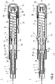
- Figure 1 shows two longitudinal sections in different section planes of an auto-injector 1, the different section planes approximately 90° rotated to each other.
- the auto-injector 1 comprises an elongate housing 2.
- a syringe 3, e.g. a Hypak syringe, with a hollow needle 4 is arranged in a proximal part of the auto-injector 1.
- a protective needle shield 5 is attached to the needle 4.
- a stopper 6 is arranged for sealing the syringe 3 distally and for displacing a liquid medicament M through the hollow needle 4.
- the syringe 3 is held in a tubular syringe carrier 7 and supported at its proximal end therein.
- a single compression spring 8 is arranged in a distal part of the auto-injector 1.
- a plunger 9 is arranged for forwarding the spring force of the compression spring 8.
- a retraction sleeve 10 is slidably arranged inside the housing 2 .
- the retraction sleeve 10 Before the injection is triggered as shown in figure 1 the retraction sleeve 10 is in a maximum proximal position and prevented from moving in distal direction D by means of stops 11 caught behind latches 12 in the housing 2.
- a distal end of the compression spring 8 bears against an end face 13 of the retraction sleeve 10. Due to the stops 11 and latches 12 the force of the compression spring 8 is thus reacted into the housing 2.
- the proximal end of the compression spring 8 bears against a decoupling member 14 arranged around the plunger 9.
- the retraction sleeve Distally from the end face 13 the retraction sleeve has two or more resilient arms 15 for holding a stud 16 and keeping it from being moved in proximal direction P.
- the stud 16 is arranged at the distal end of the plunger 9.
- the stud 16 and the resilient arms 15 have corresponding ramp features for pushing the resilient arms 15 apart in order to allow the stud 16 and the plunger 9 to move in proximal direction P.
- the decoupling member 14 comprises a thrust face 17 for bearing against a proximal end of the compression spring 8. Proximally from the thrust face 17 two or more resilient decoupling arms 18 are provided at the decoupling member 14, the decoupling arms 18 having inner ramped surfaces bearing against a first shoulder 19 in the plunger 9 in proximal direction P.
- the resilient decoupling arms 18 are supported by an inner wall of the retraction sleeve 10 in this situation so they cannot flex outward and slip past the first shoulder 19.
- a trigger button 20 is arranged at the distal end D of the auto-injector 1.
- the trigger button 20 may be pushed in proximal direction P in order to start an injection.
- the resilient arms 15 are caught between two or more retainers 21 arranged at the trigger button 20 so the resilient arms 15 cannot flex outward and the stud 16 although proximally biased by the compression spring 8 cannot slip through.
- the syringe carrier 7 is engaged for joint axial movement with a syringe holder 22 which is slidably arranged in the retraction sleeve 10.
- the syringe holder 22 is provided with two or more resilient syringe holder arms 23 arranged distally.
- the syringe holder arms 23 have a respective inclined surface for bearing against a second shoulder 24 in the plunger 9 arranged proximally from the first shoulder 19. In the initial position shown in figure 1 the syringe holder arms 23 are supported by an inner surface of the housing 2 so they cannot flex outward and the second shoulder 24 cannot slip through.
- a respective number of apertures are provided in the retraction sleeve 10.
- Figure 1 shows the auto-injector 1 as-delivered with a cap 25 screwed onto to the proximal end P of the auto-injector 1.
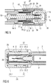
- Figure 6 shows details of the proximal end P with the cap 25.
- the cap 25 comprises a sheet metal clip 26 with two or more barbs 27 extending through an orifice into the proximal end P of the auto-injector 1.
- the sheet metal clip 26 is mounted to the cap 25 for joint axial movement with respect to a longitudinal axis of the auto-injector 1. However, the sheet metal clip 26 may rotate independently from the cap 25.
- the cap 25 is screwed onto the proximal P end of the auto-injector 1 the barbs 27 are pushed down the protective needle shield 5 and snap into a circumferential notch arranged in the protective needle shield 5 or behind a shoulder thereof.
- the first step is to unscrew the cap 25.
- the barbs 27 pull the protective needle shield 5 off the syringe 3 in proximal direction P and through the orifice making the syringe 3 ready to be used.
- a safety button 29 is arranged laterally at the distal part of the housing 2.
- the safety button 29 serves for interlocking with the trigger button 20 in a manner to prevent the trigger button 20 from being inadvertently operated without the safety button 29 being released from a first blocking position.
- the safety button 29 has to be pushed transversally with respect to the longitudinal axis against the force of a spring element 30 which is formed in the safety button 29.
- the safety button 29 is pivoted in the middle so pushing the proximal end of the safety button 29 inward pulls an interlock 31 at its proximal end obstructing the trigger button 20 outward so the trigger button 20 can be pushed.
- the second shoulder 24 pushes the syringe holder 22, syringe carrier 7 and syringe 3 forward while no load is exerted onto the stopper 6.
- the hollow needle 4 appears from the proximal end P and is inserted into an injection site, e.g. a patient's skin.
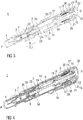
- the decoupling member 14 When the stopper 6 has nearly bottomed out in the syringe 3 (cf. figure 2 ) the decoupling member 14 has reached a position where it pushes against the latches 12 in a manner to decouple the retraction sleeve 10 from the housing 2, so the retraction sleeve 10 may slide in distal direction D.
- the compression spring 8 is no longer grounded with its distal end in the housing 2. Instead, as soon as the decoupling member 14 has bottomed out at a second abutment 33 the proximal end of the compression spring 8 gets grounded in the housing while the distal end is pulling the retraction sleeve 10 in distal direction D.
- the decoupling arms 18 reach an aperture 34 in the retraction sleeve 10 (see fig. 4 ) so they are no longer kept from being flexed outward.
- the decoupling arms 18 are thus pushed outward by the first shoulder 19 pushing against its ramped surfaces so the first shoulder 19 slips through in distal direction as soon as the decoupling member 14 has hit the second abutment 33.
- the syringe holder 22 is taken along in distal direction D by the retraction sleeve 10, e.g. by a front face 35.
- the syringe 3 and needle 4 are retracted into a safe position inside the housing 2, e.g. into the initial position.
- the plunger 9, no longer bearing against the decoupling arms 18 is pulled back too.
- a delay box 36 is arranged (see figure 5 for details).
- the delay box 36 comprises a circumferential outer wall 37 with a back collar 38 attached to the housing 2 and a circumferential inner wall 39 with a front collar 40 attached to the retraction sleeve 10.
- a volume between the outer wall 37 and inner wall 39 is filled with a viscous fluid, such as silicon grease.
- a viscous fluid such as silicon grease.
- the inner wall 39 glides along the outer wall 37 wherein the back collar 38 and front collar 40 increasingly reduce the volume.
- One or more holes (not shown) provided in a part of the delay box 36 allow the viscous fluid to be pushed out as the volume decreases. The force required to do this slows down the motion of the retraction sleeve 10.
- the retraction sleeve 10 is released by the decoupling member 14 from the housing 2 a certain amount of time or travel before the stopper 6 bottoms out in the syringe 3 and the distal motion of the retraction sleeve 10 begins.
- the motion of the retraction sleeve 10 is slowed down by the delay box 36. Due to a gap 41 between the front face 35 and the syringe holder 22 the retraction sleeve 10 is not yet dragging the syringe back in distal direction D.
- the plunger 9 is still pushing against the stopper 6 and expelling residual medicament M.
- the cap 25 and the delay box 36 are not restricted to be used with the auto-injector 1 shown in the embodiments. Instead the cap 25 may be combined with any kind of auto-injector with the needle hidden in the housing prior to an injection.
- the delay box may be combined with any kind of auto-injector for ensuring full delivery of the syringe's contents and reliable triggering of the retraction, irrespective of the spring means or driving means used in the respective auto-injector.
- the housing 2 may have at least one viewing window for inspecting the syringe 3.
- the auto-injector 1 may preferably be used for subcutaneous or intra-muscular injection, particularly for delivering one of an analgetic, an anticoagulant, insulin, an insulin derivate, heparin, Lovenox, a vaccine, a growth hormone, a peptide hormone, a proteine, antibodies and complex carbohydrates.
- the aforementioned arrangement for coupling the plunger (9) to either, the syringe (3) or the stopper (6), may be applied in any auto-injector having a plunger for forwarding a force of a drive means to a syringe with a stopper.
- the primary advantage of this arrangement ensures the load from the drive means is not transferred directly to the stopper until the needle is inserted in the patient, thus avoiding a wet injection.
- the arrangement comprises the syringe holder (22) and associated syringe holder arms (23), a shoulder (e.g.
- the spring means or other drive means the ability to retract the syringe or to forward a needle shroud after injection and other features described herein are not required for the prevention of a wet injection.
Landscapes
- Health & Medical Sciences (AREA)
- Engineering & Computer Science (AREA)
- Heart & Thoracic Surgery (AREA)
- Vascular Medicine (AREA)
- Anesthesiology (AREA)
- Biomedical Technology (AREA)
- Hematology (AREA)
- Life Sciences & Earth Sciences (AREA)
- Animal Behavior & Ethology (AREA)
- General Health & Medical Sciences (AREA)
- Public Health (AREA)
- Veterinary Medicine (AREA)
- Environmental & Geological Engineering (AREA)
- Infusion, Injection, And Reservoir Apparatuses (AREA)
Claims (8)
- Auto-injecteur (1) pour administrer une dose d'un médicament liquide (M), comprenant :- un boîtier allongé (2) prévu pour contenir une seringue (3) avec une aiguille creuse (4) et un bouchon (6) pour sceller la seringue (3) et déplacer le médicament (M), le boîtier (2) présentant une extrémité distale (D) et une extrémité proximale (P) avec un orifice prévu pour être appliqué contre un site d'injection, la seringue (3) étant disposée de manière à pouvoir coulisser par rapport au boîtier (2),- un moyen de ressort (8), qui, lorsqu'il est activé, est capable :- de pousser l'aiguille (4) d'une position couverte à l'intérieur du boîtier (2) dans une position avancée à travers l'orifice et au-delà de l'extrémité proximale (P),- d'actionner la seringue (3) pour fournir la dose de médicament (M), et- de rétracter la seringue (3) avec l'aiguille (4) dans la position couverte après l'administration du médicament (M),- un moyen d'activation (20) prévu pour verrouiller le moyen de ressort (8) dans un état pressurisé préalablement à l'actionnement manuel et, lorsqu'il est actionné manuellement, capable de libérer le moyen de ressort (8) en vue de l'injection,le moyen de ressort (8) étant un ressort de compression unique (8) prévu pour être ancré au niveau d'une extrémité distale (8.1) dans le boîtier (2) pour faire avancer l'aiguille (4) et pour injecter la dose de médicament (M) par le biais d'un plongeur (9), et le ressort de compression (8) étant prévu de manière à ce que son ancrage dans le boîtier (2) soit commuté à son extrémité proximale (8.2) tandis que l'extrémité distale (8.1) du ressort de compression (8) est libérée de son ancrage dans le boîtier (2) pour rétracter la seringue (3), caractérisé en ce qu'un manchon de rétraction (10) est disposé dans le boîtier (2) de manière à pouvoir être déplacé axialement, au moins un loquet (12) étant prévu pour fixer axialement le manchon de rétraction (10) dans une position proximale maximale, le ressort de compression (8) étant disposé à l'intérieur du manchon de rétraction (10), avec son extrémité distale pressant contre une face d'extrémité distale (13), et avec son extrémité proximale pressant contre une face de poussée (17) d'un organe de désaccouplement (14), l'organe de désaccouplement étant disposé (14) de manière à désaccoupler le loquet (12) lorsqu'il est déplacé dans la direction proximale (P) presque jusqu'à une position proximale maximale, permettant ainsi au manchon de rétraction (10) de se déplacer dans la direction distale (D) et de rétracter l'aiguille (4), au moins deux bras de désaccouplement élastiques (18) étant disposés au niveau de l'organe de désaccouplement (14), les bras de désaccouplement (18) présentant des surfaces intérieures en rampe pressant contre un premier épaulement (19) du plongeur (9) dans la direction proximale (P), les bras de désaccouplement élastiques (18) pouvant être supportés par une paroi intérieure du manchon de rétraction (10) afin d'empêcher que les bras de désaccouplement (18) ne soient fléchis vers l'extérieur et ne glissent au-delà du premier épaulement (19), et au moins une ouverture (34) étant disposée dans le manchon de rétraction (10), permettant aux bras de désaccouplement (18) d'être fléchis vers l'extérieur par le premier épaulement (19), permettant ainsi au premier épaulement (19) de glisser à travers les bras de désaccouplement (18) dans la direction proximale (P), le plongeur (9) étant prévu pour pousser la seringue (3) et/ou le bouchon (6) dans la direction proximale (P).
- Auto-injecteur (1) selon la revendication 1, caractérisé en ce que la seringue (4) est prévue pour se déplacer axialement conjointement avec un support de seringue (22) qui est disposé de manière coulissante dans le manchon de rétraction (10), le support de seringue (22) étant pourvu d'au moins deux bras de support de seringue élastiques (23) disposés distalement, les bras de support de seringue (23) présentant une surface inclinée respective destinée à presser contre un deuxième épaulement (24) qui est disposé au niveau du plongeur (9) en position proximale depuis le premier épaulement (19), les bras de support de seringue (23) pouvant être supportés par une surface intérieure du boîtier (2) afin de les empêcher d'être fléchis vers l'extérieur, et une portion élargie (2.1) étant prévue dans le boîtier (2) pour permettre aux bras de support de seringue (23) de fléchir vers l'extérieur lorsque le support de seringue (22) a presque atteint une position proximale maximale, permettant ainsi au deuxième épaulement (24) de glisser à travers les bras de support de seringue (23) et de commuter la charge du ressort de compression (8) de la seringue (3) au bouchon (6).
- Auto-injecteur (1) selon l'une des revendications 1 et 2, caractérisé en ce qu'un plot (16) est disposé au niveau de l'extrémité distale du plongeur (9), le manchon de rétraction (10) présentant au moins deux bras élastiques (15) en position distale depuis la face d'extrémité (13), pour retenir le plot (16), le plot (16) et/ou les bras élastiques (15) présentant des éléments en forme de rampe de telle sorte que les bras élastiques (15) puissent être écartés par le plot (16) lorsque le plongeur (9) est déplacé dans la direction proximale (P), les moyens d'actionnement comprenant un bouton de déclenchement (20) disposé au niveau de l'extrémité distale (D) de l'auto-injecteur (1), le bouton de déclenchement (20) étant déplaçable axialement et présentant au moins deux éléments de retenue rigides (21) pour empêcher les bras élastiques (15) d'être fléchis vers l'extérieur lorsque le bouton de déclenchement (20) est dans une position distale maximale, et, lorsque le bouton de déclenchement (20) est poussé dans la direction proximale (P), les éléments de retenue (21) étant déplacés dans la direction proximale (P) de manière à permettre aux bras élastiques (15) d'être fléchis vers l'extérieur par le plot (16) sollicité par le ressort de compression (8) dans la direction proximale (P), permettant ainsi au plot (16) de glisser au-delà des bras élastiques (15) dans la direction proximale (P).
- Auto-injecteur (1) selon la revendication 3, caractérisé en ce qu'un bouton de sécurité (29) est disposé latéralement au niveau du boîtier (2), le bouton de sécurité (29) présentant un verrouillage (31) pour empêcher que le bouton de déclenchement (20) ne soit poussé, le bouton de sécurité (29) étant prévu pour tirer le verrouillage (31) vers l'extérieur lorsqu'il est actionné, permettant ainsi au bouton de déclenchement (20) d'être poussé.
- Auto-injecteur (1) selon l'une des revendications 1 à 4, caractérisé en ce qu'un boîtier de retardement (36) est disposé de manière à ralentir le déplacement du manchon de rétraction (10), les loquets (12) étant prévus pour être désengagés par l'organe de désaccouplement (14) avant que le bouchon (6) n'ait atteint une position proximale maximale dans la seringue (3), les ouvertures (34) étant prévues pour rejoindre les bras de désaccouplement (18) après que le bouchon (6) a atteint sa position proximale maximale au moyen du déplacement du manchon de rétraction (10), et un espace (41) étant prévu entre une face avant (35) du manchon de rétraction (10) et le support de seringue (22) dans leurs positions proximales maximales respectives, l'espace (41) permettant au manchon de rétraction (10) de se déplacer d'une certaine distance avant la rétraction du support de seringue (22) de telle sorte que le support de seringue (22) soit rétracté après que les bras de désaccouplement (18) ont rejoint les ouvertures (34) .
- Auto-injecteur (1) selon la revendication 5, caractérisé en ce que le boîtier de retardement (36) comprend une paroi extérieure circonférentielle (37) avec un col arrière (38) attaché au boîtier (2) et une paroi intérieure circonférentielle (39) avec un col avant (40) attaché au manchon de rétraction (10), un volume étant défini entre la paroi extérieure (37) et la paroi intérieure (39), le volume étant scellé par le col arrière (38) et le col avant (40) et étant rempli d'un fluide visqueux, et au moins un trou étant prévu dans le boîtier de retardement (36) pour permettre au fluide visqueux d'être expulsé à mesure que le volume diminue, sous l'effet du déplacement du manchon de rétraction (10).
- Auto-injecteur (1) selon l'une des revendications précédentes, caractérisé en ce qu'un capuchon (25) est prévu au niveau de l'extrémité proximale (P) du boîtier (2), une pince en tôle métallique (26) étant attachée au capuchon (25) de manière à se déplacer axialement conjointement avec lui et à tourner indépendamment, la pince en tôle métallique (26) étant prévue pour s'étendre à travers un orifice dans le boîtier (2) lorsque le capuchon (25) est attaché au boîtier (2), la pince en tôle métallique (26) comprenant au moins deux barbes (27) encliquetées dans une encoche circonférentielle ou derrière un épaulement d'un élément de protection d'aiguille (5) attaché à l'aiguille creuse (4).
- Auto-injecteur (1) selon la revendication 7, caractérisé en ce que le capuchon (25) peut être attaché au boîtier (2) par une connexion vissée.
Priority Applications (1)
| Application Number | Priority Date | Filing Date | Title |
|---|---|---|---|
| EP11703889.3A EP2536452B1 (fr) | 2010-02-18 | 2011-02-16 | Auto-injecteur |
Applications Claiming Priority (4)
| Application Number | Priority Date | Filing Date | Title |
|---|---|---|---|
| EP10153999 | 2010-02-18 | ||
| US41208610P | 2010-11-10 | 2010-11-10 | |
| EP11703889.3A EP2536452B1 (fr) | 2010-02-18 | 2011-02-16 | Auto-injecteur |
| PCT/EP2011/052301 WO2011101379A1 (fr) | 2010-02-18 | 2011-02-16 | Injecteur automatique |
Publications (2)
| Publication Number | Publication Date |
|---|---|
| EP2536452A1 EP2536452A1 (fr) | 2012-12-26 |
| EP2536452B1 true EP2536452B1 (fr) | 2018-08-29 |
Family
ID=42286680
Family Applications (1)
| Application Number | Title | Priority Date | Filing Date |
|---|---|---|---|
| EP11703889.3A Active EP2536452B1 (fr) | 2010-02-18 | 2011-02-16 | Auto-injecteur |
Country Status (6)
| Country | Link |
|---|---|
| US (26) | US9248245B2 (fr) |
| EP (1) | EP2536452B1 (fr) |
| JP (1) | JP5807021B2 (fr) |
| CA (1) | CA2790193A1 (fr) |
| DK (1) | DK2536452T3 (fr) |
| WO (1) | WO2011101379A1 (fr) |
Families Citing this family (65)
| Publication number | Priority date | Publication date | Assignee | Title |
|---|---|---|---|---|
| ATE409057T1 (de) | 2002-02-11 | 2008-10-15 | Antares Pharma Inc | Intradermales injektionsgerät |
| WO2006079064A1 (fr) | 2005-01-24 | 2006-07-27 | Antares Pharma, Inc. | Injecteur a seringue preremplie assiste d'une aiguille |
| US20110098656A1 (en) * | 2005-09-27 | 2011-04-28 | Burnell Rosie L | Auto-injection device with needle protecting cap having outer and inner sleeves |
| WO2007131025A1 (fr) | 2006-05-03 | 2007-11-15 | Antares Pharma, Inc. | Injecteur à dosage réglable |
| US8251947B2 (en) | 2006-05-03 | 2012-08-28 | Antares Pharma, Inc. | Two-stage reconstituting injector |
| US9173997B2 (en) | 2007-10-02 | 2015-11-03 | Medimop Medical Projects Ltd. | External drug pump |
| JP5731829B2 (ja) | 2008-03-10 | 2015-06-10 | アンタレス・ファーマ・インコーポレーテッド | 注射器安全装置 |
| EP3581224A1 (fr) | 2008-08-05 | 2019-12-18 | Antares Pharma, Inc. | Injecteur à dosage multiple |
| EP2536452B1 (fr) | 2010-02-18 | 2018-08-29 | Sanofi-Aventis Deutschland GmbH | Auto-injecteur |
| EP2585138B1 (fr) * | 2010-06-28 | 2016-04-20 | Sanofi-Aventis Deutschland GmbH | Auto-injecteur |
| EP2438939A1 (fr) * | 2010-10-08 | 2012-04-11 | Sanofi-Aventis Deutschland GmbH | Agencement pour coupler un piston avec une seringue ou un butoir |
| GB2484490A (en) * | 2010-10-12 | 2012-04-18 | Owen Mumford Ltd | Frangible needle shield for syringe |
| GB201021764D0 (en) * | 2010-12-22 | 2011-02-02 | Owen Mumford Ltd | Autoinjectors |
| US8496619B2 (en) | 2011-07-15 | 2013-07-30 | Antares Pharma, Inc. | Injection device with cammed ram assembly |
| US9220660B2 (en) | 2011-07-15 | 2015-12-29 | Antares Pharma, Inc. | Liquid-transfer adapter beveled spike |
| WO2013078200A1 (fr) | 2011-11-22 | 2013-05-30 | Becton, Dickinson And Company | Système d'administration de médicament pourvu d'un mécanisme à retard |
| EP2606925A1 (fr) * | 2011-12-21 | 2013-06-26 | Sanofi-Aventis Deutschland GmbH | Auto-injecteur |
| EP2606924A1 (fr) | 2011-12-21 | 2013-06-26 | Sanofi-Aventis Deutschland GmbH | Auto-injecteur |
| PT2822618T (pt) | 2012-03-06 | 2024-03-04 | Antares Pharma Inc | Seringa pré-cheia com característica de força de rutura |
| EP2833944A4 (fr) | 2012-04-06 | 2016-05-25 | Antares Pharma Inc | Administration par injection par jet assistée par une aiguille de compositions de testostérone |
| US9364610B2 (en) | 2012-05-07 | 2016-06-14 | Antares Pharma, Inc. | Injection device with cammed ram assembly |
| CN202699780U (zh) * | 2012-06-14 | 2013-01-30 | 甘肃成纪生物药业有限公司 | 卡式半自动注射笔 |
| CN202699778U (zh) * | 2012-06-14 | 2013-01-30 | 甘肃成纪生物药业有限公司 | 卡式全自动注射笔 |
| US9675754B2 (en) | 2012-10-24 | 2017-06-13 | Nuance Designs, LLC | Autoinjector |
| PT2953667T (pt) | 2013-02-11 | 2020-01-28 | Antares Pharma Inc | Dispositivo de injeção a jato auxiliado por agulha tendo força de gatilho reduzida |
| JP6030803B2 (ja) | 2013-03-11 | 2016-11-24 | アンタレス・ファーマ・インコーポレーテッド | ピニオンシステムを有する用量注射器 |
| GB2515039B (en) | 2013-06-11 | 2015-05-27 | Cilag Gmbh Int | Injection Device |
| GB2515038A (en) | 2013-06-11 | 2014-12-17 | Cilag Gmbh Int | Injection device |
| GB2517896B (en) | 2013-06-11 | 2015-07-08 | Cilag Gmbh Int | Injection device |
| GB2515032A (en) | 2013-06-11 | 2014-12-17 | Cilag Gmbh Int | Guide for an injection device |
| EP2823841A1 (fr) | 2013-07-09 | 2015-01-14 | Sanofi-Aventis Deutschland GmbH | Auto-injecteur |
| GB201313888D0 (en) | 2013-08-02 | 2013-09-18 | Consort Medical Plc | Assembly for an autoinjector device |
| GB2519971B (en) * | 2013-11-01 | 2017-06-14 | Consort Medical Plc | Medicament delivery device sub-assembly |
| EP2902061A1 (fr) | 2014-01-30 | 2015-08-05 | Sanofi-Aventis Deutschland GmbH | Dispositifs d'administration de médicaments |
| HK1226341A1 (zh) * | 2014-02-11 | 2017-09-29 | Eli Lilly And Company | 抓取刚性针罩的盖组件 |
| EP2923714A1 (fr) | 2014-03-28 | 2015-09-30 | Sanofi-Aventis Deutschland GmbH | Auto-injecteur declenché par contact avec la peau |
| GB201416985D0 (en) * | 2014-09-26 | 2014-11-12 | Ucb Biopharma Sprl And Bespak Europ Ltd | Housing part for an auto-injector |
| LT3226944T (lt) * | 2014-12-03 | 2019-07-25 | Eli Lilly And Company | Adatos apsauginio elemento nuimtuvo dangtelio blokas |
| AU2015372441A1 (en) | 2014-12-23 | 2017-08-10 | Automed Pty Ltd | Delivery apparatus, system and associated methods |
| US10576207B2 (en) | 2015-10-09 | 2020-03-03 | West Pharma. Services IL, Ltd. | Angled syringe patch injector |
| JP7017512B2 (ja) | 2015-10-09 | 2022-02-08 | ウェスト ファーマ サービシーズ イスラエル リミテッド | 充填済流体容器の屈曲流体路型付属物 |
| JP6542481B2 (ja) | 2016-01-21 | 2019-07-10 | ウェスト ファーマ サービシーズ イスラエル リミテッド | システム |
| US11311674B2 (en) | 2016-01-21 | 2022-04-26 | West Pharma. Services IL, Ltd. | Medicament delivery device comprising a visual indicator |
| EP3711793B1 (fr) | 2016-01-21 | 2021-12-01 | West Pharma Services IL, Ltd. | Procédé de connexion d'une cartouche sur un injecteur automatique |
| EP3427244B1 (fr) | 2016-03-07 | 2020-09-09 | SHL Medical AG | Dispositif d'apprentissage d'injection automatique |
| US11389597B2 (en) | 2016-03-16 | 2022-07-19 | West Pharma. Services IL, Ltd. | Staged telescopic screw assembly having different visual indicators |
| JP2019516490A (ja) * | 2016-05-18 | 2019-06-20 | サノフィ−アベンティス・ドイチュラント・ゲゼルシャフト・ミット・ベシュレンクテル・ハフツング | シースリムーバおよびその組み立て方法 |
| US10363378B2 (en) | 2016-06-15 | 2019-07-30 | Shl Medical Ag | Cap assembly for medicament delivery device |
| CA3027992C (fr) | 2016-06-22 | 2021-08-03 | Antares Pharma, Inc. | Dispositif de retrait de protege-aiguille |
| JP7018926B2 (ja) | 2016-07-14 | 2022-02-14 | サノフィ-アベンティス・ドイチュラント・ゲゼルシャフト・ミット・ベシュレンクテル・ハフツング | 薬物送達デバイス |
| EP3490643B1 (fr) | 2016-08-01 | 2021-10-27 | West Pharma. Services Il, Ltd. | Broche de cartouche anti-rotation |
| EP3978047B1 (fr) | 2016-08-01 | 2023-08-23 | West Pharma Services IL, Ltd | Ressort pour prévenir la fermeture incomplète de la porte |
| US10814073B2 (en) * | 2016-12-13 | 2020-10-27 | Becton, Dickinson And Company | Safety device with collapsible housing and trigger activation |
| EP3630226B1 (fr) | 2017-05-30 | 2025-10-22 | West Pharma. Services Il, Ltd. | Train d'entraînement modulaire pour injecteur pouvant être porté |
| DK3706841T3 (da) | 2017-11-07 | 2023-12-11 | Shl Medical Ag | Kanyleskjoldsfjerner og medikamentafgivelsesindretning, der omfatter kanyleskjoldsfjerneren |
| EP3492126A1 (fr) | 2017-12-01 | 2019-06-05 | Sanofi | Dispositif d'injecteur |
| AU2019208338B2 (en) | 2018-01-19 | 2024-11-07 | Birya Biotech, Inc. | Tool for servicing an auto-injector |
| EP3626291A1 (fr) * | 2018-09-21 | 2020-03-25 | Regeneron Pharmaceuticals, Inc. | Dispositifs de préhension de protection d'aiguille et procédés associés |
| WO2020070328A1 (fr) | 2018-10-05 | 2020-04-09 | Phillips-Medisize A/S | Auto-injecteur avec système d'insertion efficace |
| WO2020216918A1 (fr) | 2019-04-26 | 2020-10-29 | Becton Dickinson France | Couvre-aiguille à contre-dépouille |
| EP4516343A3 (fr) | 2019-05-06 | 2025-05-14 | Battelle Memorial Institute | Auto-injecteur et procédé d'injection de fluides |
| US20220305213A1 (en) * | 2019-08-12 | 2022-09-29 | West Pharmaceutical Services, Inc. | Palm activated drug delivery device |
| US11957542B2 (en) | 2020-04-30 | 2024-04-16 | Automed Patent Holdco, Llc | Sensing complete injection for animal injection device |
| GB2623521B (en) * | 2022-10-17 | 2025-09-10 | Owen Mumford Ltd | Injection device |
| EP4487887A1 (fr) | 2023-07-03 | 2025-01-08 | Ypsomed AG | Ressort d'entraînement et ressort de recouvrement d'aiguille pour un dispositif d'injection |
Family Cites Families (205)
| Publication number | Priority date | Publication date | Assignee | Title |
|---|---|---|---|---|
| US3712301A (en) | 1971-01-11 | 1973-01-23 | Survival Technology | Gun type hypodermic injector with rapid cartridge displacement within holder |
| US4394863A (en) | 1981-10-23 | 1983-07-26 | Survival Technology, Inc. | Automatic injector with cartridge having separate sequentially injectable medicaments |
| US4976701A (en) | 1987-09-25 | 1990-12-11 | Nordisk Gentofte A/S | Injection apparatus |
| GB8926825D0 (en) | 1989-11-28 | 1990-01-17 | Glaxo Group Ltd | Device |
| GB9111600D0 (en) | 1991-05-30 | 1991-07-24 | Owen Mumford Ltd | Improvements relating to injection devices |
| US5267963A (en) | 1992-08-21 | 1993-12-07 | Nicholas Bachynsky | Medication injection device |
| GB9310163D0 (en) * | 1993-05-18 | 1993-06-30 | Owen Mumford Ltd | Improvements relating to injection devices |
| US5358489A (en) | 1993-05-27 | 1994-10-25 | Washington Biotech Corporation | Reloadable automatic or manual emergency injection system |
| US5478316A (en) | 1994-02-02 | 1995-12-26 | Becton, Dickinson And Company | Automatic self-injection device |
| GB9412301D0 (en) * | 1994-06-17 | 1994-08-10 | Safe T Ltd | Hollow-needle drugs etc applicators |
| AU1860697A (en) * | 1995-09-08 | 1997-07-28 | Visionary Medical Products Corporation | Pen-type injector drive mechanism |
| US5843036A (en) | 1996-08-23 | 1998-12-01 | Becton Dickinson And Company | Non-dosing cartridge for an injection device |
| CZ297361B6 (cs) | 1998-01-30 | 2006-11-15 | Novo Nordisk A/S | Injekcní stríkacka |
| GB9808408D0 (en) | 1998-04-18 | 1998-06-17 | Owen Mumford Ltd | Improvements relating to injection devices |
| DE19819409A1 (de) | 1998-04-30 | 1999-11-11 | Schering Ag | Injektionsvorrichtung |
| DE19822031C2 (de) | 1998-05-15 | 2000-03-23 | Disetronic Licensing Ag | Autoinjektionsgerät |
| SE9803662D0 (sv) * | 1998-10-26 | 1998-10-26 | Pharmacia & Upjohn Ab | Autoinjector |
| US6277099B1 (en) | 1999-08-06 | 2001-08-21 | Becton, Dickinson And Company | Medication delivery pen |
| US6673035B1 (en) | 1999-10-22 | 2004-01-06 | Antares Pharma, Inc. | Medical injector and medicament loading system for use therewith |
| US6692472B2 (en) | 2000-05-04 | 2004-02-17 | Novo Nordisk A/S | Injection device, a preassembled dose setting and injection mechanism for an injection device, and a method of assembling an injection device |
| US6663602B2 (en) | 2000-06-16 | 2003-12-16 | Novo Nordisk A/S | Injection device |
| WO2002009797A1 (fr) * | 2000-08-02 | 2002-02-07 | Becton Dickinson And Company | Aiguille stylo et systeme de blindage de securite |
| WO2002017996A1 (fr) | 2000-08-29 | 2002-03-07 | Novo Nordisk A/S | Dispositif automatique d'injection a retrait de l'aiguille par torsion |
| SE518981C2 (sv) | 2000-12-14 | 2002-12-17 | Shl Medical Ab | Autoinjektor |
| EP2275158B1 (fr) | 2001-05-16 | 2013-01-23 | Eli Lilly and Company | Appareil injecteur de médication |
| US20030105430A1 (en) * | 2001-11-30 | 2003-06-05 | Elan Pharma International Limited Wil House | Automatic injector |
| EP1472477B1 (fr) | 2002-01-25 | 2005-11-16 | Novo Nordisk A/S | Actionneur lineaire et dispositif distributeur medical comprenant un tel actionneur |
| GB0211294D0 (en) | 2002-05-17 | 2002-06-26 | Owen Mumford Ltd | Improvements relating to injection devices |
| WO2004011065A1 (fr) | 2002-07-31 | 2004-02-05 | Alza Corporation | Dispositif d'injection a retraction d'aiguille automatique |
| DE10237258B4 (de) | 2002-08-14 | 2006-09-21 | Tecpharma Licensing Ag | Injektionsvorrichtung |
| GB0224505D0 (en) | 2002-10-22 | 2002-11-27 | Medical House The Plc | Needles injection device |
| GB0229345D0 (en) | 2002-12-17 | 2003-01-22 | Safe T Ltd | Hollow needle applicators |
| GB0304822D0 (en) | 2003-03-03 | 2003-04-09 | Dca Internat Ltd | Improvements in and relating to a pen-type injector |
| US9205197B2 (en) * | 2003-03-03 | 2015-12-08 | Sanofi-Aventis Deutschland Gmbh | Drug delivery device dose setting mechanism |
| US20050027255A1 (en) | 2003-07-31 | 2005-02-03 | Sid Technologies, Llc | Automatic injector |
| TR201903984T4 (tr) | 2003-08-12 | 2019-04-22 | Lilly Co Eli | Mekanik avantaja yönelik üçlü vida dişine sahip ilaç dağıtım aparatı. |
| US20050101919A1 (en) * | 2003-11-07 | 2005-05-12 | Lennart Brunnberg | Device for an injector |
| EP1541185A1 (fr) | 2003-12-08 | 2005-06-15 | Novo Nordisk A/S | Seringue automatique avec mécanisme d'amorçage |
| ATE446112T1 (de) | 2003-12-18 | 2009-11-15 | Tecpharma Licensing Ag | Auslösbares injektionsgerät |
| CH696421A5 (de) | 2003-12-18 | 2007-06-15 | Tecpharma Licensing Ag | Autoinjektor mit Arretierung des Wirkstoffbehälters. |
| ES2296129T3 (es) | 2004-01-23 | 2008-04-16 | The Medical House Plc | Dispositivo de inyeccion. |
| GB2410188B (en) | 2004-01-23 | 2006-01-25 | Medical House Plc | Injection device |
| US20050222539A1 (en) | 2004-03-30 | 2005-10-06 | Pediamed Pharmaceuticals, Inc. | Automatic injection device |
| GB2414401B (en) | 2004-05-28 | 2009-06-17 | Cilag Ag Int | Injection device |
| GB2414404B (en) | 2004-05-28 | 2009-06-03 | Cilag Ag Int | Injection device |
| GB2414400B (en) * | 2004-05-28 | 2009-01-14 | Cilag Ag Int | Injection device |
| GB2414399B (en) | 2004-05-28 | 2008-12-31 | Cilag Ag Int | Injection device |
| GB2414402B (en) | 2004-05-28 | 2009-04-22 | Cilag Ag Int | Injection device |
| US8357120B2 (en) | 2004-10-21 | 2013-01-22 | Novo Nordisk A/S | Injection device with torsion spring and rotatable display |
| JP4990151B2 (ja) | 2004-10-21 | 2012-08-01 | ノボ・ノルデイスク・エー/エス | 内部投与量表示器を備えた注射器 |
| CN101119761B (zh) | 2004-11-24 | 2010-08-18 | Shl医药公司 | 注射设备 |
| DE102004063647A1 (de) | 2004-12-31 | 2006-07-20 | Tecpharma Licensing Ag | Vorrichtung zur dosierten Verabreichung eines fluiden Produkts mit Kupplung |
| JP4903160B2 (ja) | 2005-01-18 | 2012-03-28 | ウォックハート アメリカズ インコーポレイテッド | ペン型薬物注入デバイス |
| PL1843809T3 (pl) | 2005-01-21 | 2017-09-29 | Novo Nordisk A/S | Automatyczne urządzenie wstrzykujące z górnym mechanizmem wyzwalania |
| WO2006079064A1 (fr) | 2005-01-24 | 2006-07-27 | Antares Pharma, Inc. | Injecteur a seringue preremplie assiste d'une aiguille |
| GB2424836B (en) | 2005-04-06 | 2010-09-22 | Cilag Ag Int | Injection device (bayonet cap removal) |
| US9011386B2 (en) | 2005-06-01 | 2015-04-21 | Shl Group Ab | Device for delivering medicament |
| ATE401921T1 (de) | 2005-06-01 | 2008-08-15 | Shl Medical Ab | Medikamentenabgabevorrichtung |
| DE102005025424A1 (de) | 2005-06-02 | 2006-12-07 | Tecpharma Licensing Ag | Injektionsvorrichtung mit einem Drehfederantrieb |
| EP1904130B1 (fr) | 2005-06-21 | 2016-03-30 | Eli Lilly And Company | Dispositif d'administration de medicament muni d'une aiguille a insertion d'aiguille a declenchement automatique et a injection de medicament a commande manuelle |
| CN101217989B (zh) | 2005-07-08 | 2010-10-20 | 诺沃-诺迪斯克有限公司 | 注射装置 |
| DE102005038933A1 (de) | 2005-08-17 | 2007-02-22 | L + N Plast Vertriebs Gmbh | Autoinjektionsgerät |
| CN101282752A (zh) | 2005-10-11 | 2008-10-08 | 伊莱利利公司 | 用于注射药物的设备 |
| DE102005052502A1 (de) | 2005-11-03 | 2007-05-16 | Tecpharma Licensing Ag | Autoinjektor-Aktivierung Auslöseelement |
| GB2433032A (en) | 2005-12-08 | 2007-06-13 | Owen Mumford Ltd | Syringe with dose adjustment means |
| US7988675B2 (en) | 2005-12-08 | 2011-08-02 | West Pharmaceutical Services Of Delaware, Inc. | Automatic injection and retraction devices for use with pre-filled syringe cartridges |
| GB0601309D0 (en) | 2006-01-23 | 2006-03-01 | Medical House The Plc | Injection device |
| US20070173770A1 (en) | 2006-01-23 | 2007-07-26 | The Medical House Plc | Injection device |
| US20090005735A1 (en) | 2006-03-03 | 2009-01-01 | Shl Group Ab | Medical Device with Orientation Sensitive Priming Mechanism |
| FR2899482A1 (fr) | 2006-04-11 | 2007-10-12 | Becton Dickinson France Soc Pa | Dispositif d'injection automatique |
| WO2007129324A2 (fr) | 2006-05-09 | 2007-11-15 | Gil Yigal | dispositif d'injection jetable avec mÉcanisme d'auto-rÉtraction |
| GB2438590B (en) * | 2006-06-01 | 2011-02-09 | Cilag Gmbh Int | Injection device |
| GB2438592B (en) | 2006-06-01 | 2011-04-06 | Cilag Gmbh Int | Injection device |
| DE102006038103B4 (de) | 2006-08-14 | 2017-02-23 | Tecpharma Licensing Ag | Injektionsvorrichtung mit variabler Gewindeführung |
| FR2905273B1 (fr) | 2006-09-06 | 2009-04-03 | Becton Dickinson France Soc Pa | Dispositif d'injection automatique avec moyen de temporisation. |
| EP3626289B1 (fr) | 2006-09-15 | 2020-12-02 | Ypsomed AG | Appareil d'injection à élément d'extraction amélioré |
| FR2908753B1 (fr) | 2006-11-16 | 2011-11-11 | Becton Dickinson France | Dispositif pour delivrer automatiquement des doses successives de produit |
| ES2365931T3 (es) * | 2006-12-13 | 2011-10-13 | Shl Group Ab | Inyector automático. |
| GB0625169D0 (en) | 2006-12-18 | 2007-01-24 | Medical House Plc The | Improved autoinjector |
| DE202007000578U1 (de) | 2007-01-15 | 2007-03-08 | Cilag Gmbh International | Injektionsvorrichtung |
| GB0704351D0 (en) | 2007-03-07 | 2007-04-11 | Medical House Plc The | Improved autoinjector |
| CN101641125B (zh) | 2007-03-09 | 2013-06-19 | 伊莱利利公司 | 用于自动注射设备的延迟机构 |
| EP2129416A1 (fr) | 2007-03-22 | 2009-12-09 | Tecpharma Licensing AG | Ensemble ressort dans un dispositif d'injection |
| EP2131898B1 (fr) | 2007-03-23 | 2017-08-30 | SHL Group AB | Auto-injecteur |
| EP2144649B1 (fr) | 2007-04-05 | 2011-07-20 | Tecpharma Licensing AG | Dispositif d'administration à élément d'entraînement fonctionnel |
| DE102007016811A1 (de) | 2007-04-05 | 2008-10-09 | Tecpharma Licensing Ag | Vorrichtung zur Verabreichung eines fluiden Wirkstoffes aus einer Mehrkammerampulle |
| CA2702412C (fr) | 2007-06-19 | 2012-07-17 | Shl Group Ab | Dispositif de distribution de medicaments |
| WO2008155377A1 (fr) | 2007-06-20 | 2008-12-24 | Unomedical A/S | Aiguille invisible |
| EP2162170B1 (fr) | 2007-07-06 | 2011-03-16 | SHL Group AB | Injecteur "monocoup" et ressorts jumelés |
| US9242044B2 (en) | 2007-07-06 | 2016-01-26 | Novo Nordisk A/S | Automatic injection device |
| GB2451663B (en) | 2007-08-08 | 2012-09-26 | Cilag Gmbh Int | Injection device |
| WO2009037141A1 (fr) | 2007-09-18 | 2009-03-26 | Shl Group Ab | Dispositif d'injection automatique avec insertion d'aiguille |
| WO2009040602A1 (fr) | 2007-09-25 | 2009-04-02 | Becton Dickinson France | Dispositif d'injection automatique équipé de moyen de désactivation rendu mobile par une protection de sécurité |
| JP5216859B2 (ja) | 2007-09-25 | 2013-06-19 | ベクトン・ディキンソン・フランス・エス.エー.エス. | 改変を証明する手段を有する遮へい分離部を備えた自動注射器 |
| US8357125B2 (en) | 2007-09-25 | 2013-01-22 | Becton, Dickinson And Company | Autoinjector with deactivating means moveable by a safety shield |
| US8313470B2 (en) | 2007-09-25 | 2012-11-20 | Becton Dickinson France | Autoinjector |
| WO2009062510A1 (fr) | 2007-11-12 | 2009-05-22 | Bang & Olufsen Medicom A/S | Auto-injecteur à rappel d'aiguille automatique |
| GB0724907D0 (en) | 2007-12-20 | 2008-01-30 | Ucb Pharma Sa | Auto-injector |
| CN104324438B (zh) | 2008-01-11 | 2017-06-16 | Ucb医药有限公司 | 用于类风湿性关节炎患者的给药系统 |
| US8992484B2 (en) | 2008-01-23 | 2015-03-31 | Novo Nordisk A/S | Device for injecting apportioned doses of liquid drug |
| AU2009214255B2 (en) | 2008-02-12 | 2011-09-29 | Shl Medical Ag | Auto-injector |
| DE102008011885A1 (de) | 2008-02-29 | 2009-09-10 | Tecpharma Licensing Ag | Doppelfunktionsfeder |
| EP2123317A1 (fr) | 2008-05-20 | 2009-11-25 | Sanofi-Aventis Deutschland GmbH | Ensemble de commande adapté pour dispositif d'administration de médicaments et dispositif d'administration de médicaments |
| EP2303365B1 (fr) | 2008-05-20 | 2017-07-26 | SHL Group AB | Dispositif pour dispositif d' administration de médicaments |
| US7811261B2 (en) | 2008-06-02 | 2010-10-12 | Sta-Med, Llc | Needle cover assembly for a syringe |
| PL3581223T3 (pl) * | 2008-07-18 | 2024-11-25 | UCB Biopharma SRL | Systemy automatycznego podawania leków |
| EP3581224A1 (fr) | 2008-08-05 | 2019-12-18 | Antares Pharma, Inc. | Injecteur à dosage multiple |
| WO2010033790A2 (fr) | 2008-09-18 | 2010-03-25 | Becton, Dickinson And Company | Injecteur médical présentant des parties de corps pivotantes |
| US8403883B2 (en) | 2008-09-18 | 2013-03-26 | Becton, Dickinson And Company | Medical injector with dose knob activation for automated reconstitution |
| JP5324656B2 (ja) | 2008-10-01 | 2013-10-23 | エス・ホー・エル・グループ・アクチボラゲット | 渦巻きバネにより駆動する薬剤送達装置 |
| TWI555546B (zh) | 2008-12-02 | 2016-11-01 | 賽諾菲阿凡提斯德意志有限公司 | 藥物傳輸裝置及其操作方法 |
| EP2196233A1 (fr) | 2008-12-12 | 2010-06-16 | Sanofi-Aventis Deutschland GmbH | Mécanisme de commande réenclenchable pour dispositif d'administration de médicaments et dispositif d'administration de médicaments |
| AU2009324406B2 (en) | 2008-12-12 | 2014-12-11 | Sanofi-Aventis Deutschland Gmbh | Resettable drive mechanism for a medication delivery device and medication delivery device |
| EP2196232A1 (fr) | 2008-12-12 | 2010-06-16 | Sanofi-Aventis Deutschland GmbH | Mécanisme de commande pour dispositif d'administration de médicaments et dispositif d'administration de médicaments |
| US9089652B2 (en) | 2008-12-12 | 2015-07-28 | Sanofi-Aventis Deutschland Gmbh | Drive mechanism for a medication delivery device and medication delivery device |
| US8968258B2 (en) | 2008-12-12 | 2015-03-03 | Sanofi-Aventis Deutschland Gmbh | Resettable drive mechanism for a medication delivery device and medication delivery device |
| GB0900930D0 (en) | 2009-01-20 | 2009-03-04 | Future Injection Technologies Ltd | Injection device |
| EP2208503A1 (fr) | 2009-01-20 | 2010-07-21 | Sanofi-Aventis Deutschland GmbH | Ensemble de commande et dispositif d'administration de médicaments |
| BRPI1008514A2 (pt) | 2009-02-05 | 2016-03-08 | Sanofi Aventis Deutschland | "dispositivo de envio de medicamento" |
| KR20110113203A (ko) | 2009-02-05 | 2011-10-14 | 사노피-아벤티스 도이칠란트 게엠베하 | 약제 전달 디바이스 |
| EP2401009B1 (fr) | 2009-02-26 | 2012-11-28 | Tecpharma Licensing AG | Support de réservoir à produit pour un dispositif d'injection et pour la réception d'un réservoir à produit |
| ES2658855T3 (es) | 2009-03-13 | 2018-03-12 | Eli Lilly And Company | Aparato para inyectar un fármaco con retracción automática de la jeringa tras la inyección |
| AU2010226442A1 (en) | 2009-03-20 | 2011-10-13 | Antares Pharma, Inc. | Hazardous agent injection system |
| WO2010112376A1 (fr) | 2009-03-31 | 2010-10-07 | Sanofi-Aventis Deutschland Gmbh | Améliorations concernant des dispositifs d'administration de médicament |
| DK2255842T4 (da) * | 2009-05-26 | 2023-07-24 | Shl Medical Ag | Nålekappeaggregat |
| WO2010136077A1 (fr) | 2009-05-29 | 2010-12-02 | Tecpharma Licensing Ag | Dispositif d'injection, en particulier auto-injecteur comprenant un dispositif de commutation destiné à un manchon de protection d'aiguille |
| AU2010254627B2 (en) | 2009-06-05 | 2012-08-02 | Shl Group Ab | Medicament delivery device |
| GB0913385D0 (en) | 2009-07-31 | 2009-09-16 | Medical House The Plc | Improved autoinjector |
| EP2467183B1 (fr) | 2009-08-19 | 2020-01-08 | Safety Syringes, Inc. | Dispositif de sécurité actif contre les piqûres d'aiguille en contact avec un patient |
| TW201127435A (en) | 2009-09-30 | 2011-08-16 | Sanofi Aventis Deutschland | Drive mechanism for a drug delivery device |
| JP5701889B2 (ja) * | 2009-10-08 | 2015-04-15 | エス・ホー・エル・グループ・アクチボラゲットShl Group Ab | 薬物供給装置 |
| WO2011047298A2 (fr) | 2009-10-16 | 2011-04-21 | Centocor Ortho Biotech Inc. | Dispositif d'administration de médicament activé par la paume |
| US9233213B2 (en) | 2009-10-16 | 2016-01-12 | Janssen Biotech, Inc. | Palm activated drug delivery device |
| GB0918145D0 (en) | 2009-10-16 | 2009-12-02 | Owen Mumford Ltd | Injector apparatus |
| DK2493529T3 (en) | 2009-10-26 | 2016-05-17 | Shl Group Ab | Drug delivery device |
| US8758301B2 (en) | 2009-12-15 | 2014-06-24 | Abbvie Biotechnology Ltd | Firing button for automatic injection device |
| ES2537654T3 (es) | 2009-12-16 | 2015-06-10 | Becton Dickinson And Company | Dispositivo de autoinyección |
| DK2536453T3 (en) | 2010-02-18 | 2014-11-24 | Sanofi Aventis Deutschland | autoinjector |
| WO2011101378A1 (fr) | 2010-02-18 | 2011-08-25 | Sanofi-Aventis Deutschland Gmbh | Gaine d'aiguille pour un dispositif d'injection |
| EP2536452B1 (fr) | 2010-02-18 | 2018-08-29 | Sanofi-Aventis Deutschland GmbH | Auto-injecteur |
| JP5805111B2 (ja) | 2010-02-18 | 2015-11-04 | サノフィ−アベンティス・ドイチュラント・ゲゼルシャフト・ミット・ベシュレンクテル・ハフツング | トーションばねを備えた自動注射器 |
| JP5807022B2 (ja) * | 2010-02-18 | 2015-11-10 | サノフィ−アベンティス・ドイチュラント・ゲゼルシャフト・ミット・ベシュレンクテル・ハフツング | 自動注射器 |
| WO2011101381A2 (fr) | 2010-02-22 | 2011-08-25 | Sanofi-Aventis Deutschland Gmbh | Boîte de vitesse |
| WO2011101383A1 (fr) | 2010-02-22 | 2011-08-25 | Sanofi-Aventis Deutschland Gmbh | Agencement de transmission de force pour auto-injecteur |
| CA2790280A1 (fr) | 2010-02-22 | 2011-08-25 | Sanofi-Aventis Deutschland Gmbh | Auto-injecteur avec fourreau d'aiguille et capuchon de protection d'aiguille |
| ES2484266T3 (es) | 2010-03-01 | 2014-08-11 | Eli Lilly And Company | Dispositivo de inyección automático con mecanismo de retardo incluyendo un elemento de empuje de función doble |
| EP2544741B1 (fr) | 2010-03-09 | 2016-05-11 | SHL Group AB | Dispositif d'administration de médicament |
| EP2364741A1 (fr) * | 2010-03-09 | 2011-09-14 | Sanofi-Aventis Deutschland GmbH | Mécanisme d'interverrouillage pour la définition d'une séquence d'opération d'un auto-injecteur |
| EP2364740A1 (fr) | 2010-03-09 | 2011-09-14 | Sanofi-Aventis Deutschland GmbH | Agencement pour transférer une translation de moyen de commande à un piston |
| IT1398501B1 (it) | 2010-03-10 | 2013-03-01 | Menarini Int Operations Lu Sa | Dispositivo autoiniettore di due dosi di farmaco |
| BR112012024238A2 (pt) | 2010-03-25 | 2019-09-24 | New Injection Systems Ltd | injetor |
| DK2552517T3 (en) | 2010-03-31 | 2017-04-03 | Shl Group Ab | PHARMACEUTICAL DELIVERY DEVICE INCLUDING FEEDBACK SIGNALS |
| US9327083B2 (en) | 2010-04-07 | 2016-05-03 | Shl Group Ab | Medicament delivery device |
| WO2011136718A1 (fr) | 2010-04-26 | 2011-11-03 | Shl Group Ab | Dispositif d'administration de médicament |
| CN102946926B (zh) | 2010-05-07 | 2014-12-10 | Shl集团有限责任公司 | 药物输送设备 |
| US8961473B2 (en) | 2010-06-11 | 2015-02-24 | Sanofi-Aventis Deutschland Gmbh | Drive mechanism for a drug delivery device and drug delivery device |
| CA2801158A1 (fr) | 2010-06-11 | 2011-12-15 | Sanofi-Aventis Deutschland Gmbh | Mecanisme d'entrainement pour un dispositif de distribution de medicament et dispositif de distribution de medicament |
| WO2011154486A1 (fr) | 2010-06-11 | 2011-12-15 | Sanofi-Aventis Deutschland Gmbh | Mécanisme d'entraînement pour dispositif d'administration de médicaments et dispositif d'administration de médicaments |
| US8728040B2 (en) * | 2010-06-23 | 2014-05-20 | Tcb Medical Devices, Llc | Injector for auto-injection of medication and associated method of use |
| EP2399633A1 (fr) | 2010-06-28 | 2011-12-28 | Sanofi-Aventis Deutschland GmbH | Agencement de sécurité d'aiguille et son procédé de fonctionnement |
| EP2399631A1 (fr) | 2010-06-28 | 2011-12-28 | Sanofi-Aventis Deutschland GmbH | Auto-injecteur avec élément d'amortissement d'injection |
| EP2585138B1 (fr) | 2010-06-28 | 2016-04-20 | Sanofi-Aventis Deutschland GmbH | Auto-injecteur |
| EP2399635A1 (fr) | 2010-06-28 | 2011-12-28 | Sanofi-Aventis Deutschland GmbH | Auto-injecteur |
| EP2399634A1 (fr) | 2010-06-28 | 2011-12-28 | Sanofi-Aventis Deutschland GmbH | Agencement de sécurité d'aiguille et son procédé de fonctionnement |
| CN103328026B (zh) | 2010-07-02 | 2015-05-13 | 卡勒贝控股有限公司,公司编号:681498 | 无防腐剂的促卵泡激素溶液的递送装置 |
| EP2588162B1 (fr) | 2010-07-02 | 2020-01-01 | Sanofi-Aventis Deutschland GmbH | Dispositif de sécurité pour seringue pré-remplie et dispositif d'injection |
| EP2624882B1 (fr) | 2010-10-06 | 2021-04-28 | Ypsomed AG | Mécanisme de verrouillage et de retenue pour le protecteur d'aiguille d'un dispositif d'injection |
| EP2438944A1 (fr) | 2010-10-08 | 2012-04-11 | Sanofi-Aventis Deutschland GmbH | Auto-injecteur |
| EP2438942A1 (fr) | 2010-10-08 | 2012-04-11 | Sanofi-Aventis Deutschland GmbH | Auto-injecteur |
| EP2452711A1 (fr) | 2010-11-12 | 2012-05-16 | Sanofi-Aventis Deutschland GmbH | Mécanisme de commande pour dispositif d'administration de médicaments et dispositif d'administration de médicaments |
| TWI476024B (zh) | 2010-11-18 | 2015-03-11 | Shl Group Ab | 藥物輸送裝置 |
| EP2646079A1 (fr) | 2010-11-29 | 2013-10-09 | Sanofi-Aventis Deutschland GmbH | Dispositif d'administration de médicaments ayant un collier et un composant de liaison |
| EP2468335A1 (fr) | 2010-12-21 | 2012-06-27 | Sanofi-Aventis Deutschland GmbH | Auto-injecteur |
| EP2468331A1 (fr) | 2010-12-21 | 2012-06-27 | Sanofi-Aventis Deutschland GmbH | Auto-injecteur |
| EP2468332A1 (fr) | 2010-12-21 | 2012-06-27 | Sanofi-Aventis Deutschland GmbH | Auto-injecteur |
| EP2468329A1 (fr) | 2010-12-21 | 2012-06-27 | Sanofi-Aventis Deutschland GmbH | Auto-injecteur avec ressort à torsion |
| EP2468330A1 (fr) | 2010-12-21 | 2012-06-27 | Sanofi-Aventis Deutschland GmbH | Auto-injecteur |
| EP2468336A1 (fr) | 2010-12-21 | 2012-06-27 | Sanofi-Aventis Deutschland GmbH | Auto-injecteur |
| EP2468342A1 (fr) | 2010-12-21 | 2012-06-27 | Sanofi-Aventis Deutschland GmbH | Unité initiale pour auto-injecteur |
| EP2468337A1 (fr) | 2010-12-21 | 2012-06-27 | Sanofi-Aventis Deutschland GmbH | Dispositif secondaire pour auto-injecteur et auto-injecteur |
| EP2468334A1 (fr) | 2010-12-21 | 2012-06-27 | Sanofi-Aventis Deutschland GmbH | Auto-injecteur |
| EP2468333A1 (fr) | 2010-12-21 | 2012-06-27 | Sanofi-Aventis Deutschland GmbH | Auto-injecteur |
| EP2540329A1 (fr) | 2011-06-28 | 2013-01-02 | Sanofi-Aventis Deutschland GmbH | Dispositif de fixation et de retrait d'un ensemble formant aiguille |
| CH705345A2 (de) | 2011-08-04 | 2013-02-15 | Tecpharma Licensing Ag | Injektionsvorrichtung mit Nadelschutzeinrichtung. |
| US9867940B2 (en) | 2011-12-15 | 2018-01-16 | Shl Group Ab | Auto-injection device |
| CH705992A2 (de) | 2012-10-11 | 2013-06-14 | Tecpharma Licensing Ag | Injektionsvorrichtung. |
| LT2908887T (lt) | 2012-10-19 | 2018-08-10 | Eli Lilly And Company | Automatinis įšvirkštimo įrenginys su paleidimo konstrukcija |
| EP3590568A1 (fr) | 2013-03-22 | 2020-01-08 | TecPharma Licensing AG | Dispositif de distribution de la substance pourvu de dispositif de signal |
| HK1226341A1 (zh) | 2014-02-11 | 2017-09-29 | Eli Lilly And Company | 抓取刚性针罩的盖组件 |
| CH707898A2 (de) | 2014-07-29 | 2014-10-15 | Tecpharma Licensing Ag | Autoinjektor mit einstellbarer Dosis. |
| EP3180054B1 (fr) | 2014-08-15 | 2019-12-18 | Eli Lilly and Company | Dispositif médicament d'injection automatique à indication visible de progrès d'injection |
| SG11201702609SA (en) | 2014-11-18 | 2017-04-27 | Lilly Co Eli | Thermal locking mechanism for a medication delivery device |
| LT3226944T (lt) | 2014-12-03 | 2019-07-25 | Eli Lilly And Company | Adatos apsauginio elemento nuimtuvo dangtelio blokas |
| CH711240A2 (de) | 2015-06-23 | 2016-12-30 | Tecpharma Licensing Ag | Autoinjektionsvorrichtung. |
| US11452821B2 (en) | 2017-10-12 | 2022-09-27 | Eli Lilly And Company | Needle shield puller for drug delivery system |
| PT3801694T (pt) | 2018-06-08 | 2025-10-30 | Antares Pharma Inc | Injetor de auto-inserção |
| US12434013B2 (en) | 2018-10-12 | 2025-10-07 | Sanofi | Injection device |
| EP3938013B1 (fr) | 2019-03-15 | 2023-09-27 | Eli Lilly and Company | Systeme d'injection automatique |
| US12514982B2 (en) | 2019-05-29 | 2026-01-06 | Sanofi | Assembly for a drug delivery device and drug delivery device |
| EP3999149A1 (fr) | 2019-07-18 | 2022-05-25 | SHL Medical AG | Structure de support, dispositif d'administration de médicament et méthode d'assemblage |
| WO2021160540A1 (fr) | 2020-02-11 | 2021-08-19 | Ypsomed Ag | Auto-injecteur équipé d'un manchon de protection d'aiguille |
| CH717267A2 (de) | 2020-03-30 | 2021-09-30 | Ypsomed Ag | Autoinjektor mit einem Mehrkammerproduktbehälter. |
| CH717905A2 (de) | 2020-09-30 | 2022-03-31 | Ypsomed Ag | Autoinjektor mit Ausschüttstopp. |
| US20240066225A1 (en) | 2020-11-18 | 2024-02-29 | Sanofi | Arrangement for a Drug Delivery Device and Drug Delivery Device |
| CH717046A2 (de) | 2021-03-04 | 2021-07-15 | Ypsomed Ag | Autoinjektor mit einer Nadelschutzhülse. |
-
2011
- 2011-02-16 EP EP11703889.3A patent/EP2536452B1/fr active Active
- 2011-02-16 US US13/579,435 patent/US9248245B2/en active Active
- 2011-02-16 DK DK11703889.3T patent/DK2536452T3/da active
- 2011-02-16 JP JP2012553303A patent/JP5807021B2/ja active Active
- 2011-02-16 WO PCT/EP2011/052301 patent/WO2011101379A1/fr not_active Ceased
- 2011-02-16 CA CA2790193A patent/CA2790193A1/fr not_active Abandoned
-
2016
- 2016-01-14 US US14/995,964 patent/US10232116B2/en active Active
-
2019
- 2019-02-14 US US16/276,366 patent/US11197958B2/en active Active
-
2021
- 2021-11-04 US US17/453,601 patent/US20220054752A1/en active Pending
-
2022
- 2022-03-28 US US17/706,380 patent/US12397116B2/en active Active
- 2022-06-21 US US17/845,738 patent/US11484653B1/en active Active
-
2023
- 2023-02-03 US US18/105,564 patent/US11730888B2/en active Active
-
2024
- 2024-02-27 US US18/589,038 patent/US12090302B2/en active Active
- 2024-02-27 US US18/589,009 patent/US12083319B2/en active Active
- 2024-03-29 US US18/622,107 patent/US12090303B2/en active Active
- 2024-05-30 US US18/679,377 patent/US12453818B2/en active Active
- 2024-05-30 US US18/678,521 patent/US12390593B2/en active Active
- 2024-05-30 US US18/678,364 patent/US12465688B2/en active Active
- 2024-05-30 US US18/678,282 patent/US12465687B2/en active Active
- 2024-05-31 US US18/680,366 patent/US12582774B2/en active Active
- 2024-05-31 US US18/679,896 patent/US12551625B2/en active Active
- 2024-05-31 US US18/680,212 patent/US12508367B2/en active Active
- 2024-05-31 US US18/680,073 patent/US12527916B2/en active Active
- 2024-05-31 US US18/679,813 patent/US12427257B2/en active Active
-
2025
- 2025-01-14 US US19/020,238 patent/US12409273B2/en active Active
- 2025-01-15 US US19/022,461 patent/US12533469B2/en active Active
- 2025-01-15 US US19/021,557 patent/US12589207B2/en active Active
- 2025-01-15 US US19/021,912 patent/US12397117B2/en active Active
- 2025-01-15 US US19/021,396 patent/US12409274B2/en active Active
- 2025-09-11 US US19/326,485 patent/US20260007826A1/en active Pending
- 2025-09-11 US US19/326,409 patent/US20260007825A1/en active Pending
Also Published As
Similar Documents
| Publication | Publication Date | Title |
|---|---|---|
| US12409273B2 (en) | Auto-injector |
Legal Events
| Date | Code | Title | Description |
|---|---|---|---|
| PUAI | Public reference made under article 153(3) epc to a published international application that has entered the european phase |
Free format text: ORIGINAL CODE: 0009012 |
|
| 17P | Request for examination filed |
Effective date: 20120918 |
|
| AK | Designated contracting states |
Kind code of ref document: A1 Designated state(s): AL AT BE BG CH CY CZ DE DK EE ES FI FR GB GR HR HU IE IS IT LI LT LU LV MC MK MT NL NO PL PT RO RS SE SI SK SM TR |
|
| AX | Request for extension of the european patent |
Extension state: BA ME |
|
| 17Q | First examination report despatched |
Effective date: 20140304 |
|
| STAA | Information on the status of an ep patent application or granted ep patent |
Free format text: STATUS: EXAMINATION IS IN PROGRESS |
|
| GRAP | Despatch of communication of intention to grant a patent |
Free format text: ORIGINAL CODE: EPIDOSNIGR1 |
|
| STAA | Information on the status of an ep patent application or granted ep patent |
Free format text: STATUS: GRANT OF PATENT IS INTENDED |
|
| INTG | Intention to grant announced |
Effective date: 20180322 |
|
| GRAS | Grant fee paid |
Free format text: ORIGINAL CODE: EPIDOSNIGR3 |
|
| GRAA | (expected) grant |
Free format text: ORIGINAL CODE: 0009210 |
|
| STAA | Information on the status of an ep patent application or granted ep patent |
Free format text: STATUS: THE PATENT HAS BEEN GRANTED |
|
| AK | Designated contracting states |
Kind code of ref document: B1 Designated state(s): AL AT BE BG CH CY CZ DE DK EE ES FI FR GB GR HR HU IE IS IT LI LT LU LV MC MK MT NL NO PL PT RO RS SE SI SK SM TR |
|
| AX | Request for extension of the european patent |
Extension state: BA ME |
|
| REG | Reference to a national code |
Ref country code: GB Ref legal event code: FG4D |
|
| REG | Reference to a national code |
Ref country code: CH Ref legal event code: EP |
|
| REG | Reference to a national code |
Ref country code: AT Ref legal event code: REF Ref document number: 1034398 Country of ref document: AT Kind code of ref document: T Effective date: 20180915 |
|
| REG | Reference to a national code |
Ref country code: IE Ref legal event code: FG4D |
|
| REG | Reference to a national code |
Ref country code: DE Ref legal event code: R096 Ref document number: 602011051491 Country of ref document: DE |
|
| REG | Reference to a national code |
Ref country code: SE Ref legal event code: TRGR |
|
| REG | Reference to a national code |
Ref country code: DK Ref legal event code: T3 Effective date: 20181217 Ref country code: NL Ref legal event code: MP Effective date: 20180829 |
|
| REG | Reference to a national code |
Ref country code: LT Ref legal event code: MG4D |
|
| PG25 | Lapsed in a contracting state [announced via postgrant information from national office to epo] |
Ref country code: LT Free format text: LAPSE BECAUSE OF FAILURE TO SUBMIT A TRANSLATION OF THE DESCRIPTION OR TO PAY THE FEE WITHIN THE PRESCRIBED TIME-LIMIT Effective date: 20180829 Ref country code: RS Free format text: LAPSE BECAUSE OF FAILURE TO SUBMIT A TRANSLATION OF THE DESCRIPTION OR TO PAY THE FEE WITHIN THE PRESCRIBED TIME-LIMIT Effective date: 20180829 Ref country code: IS Free format text: LAPSE BECAUSE OF FAILURE TO SUBMIT A TRANSLATION OF THE DESCRIPTION OR TO PAY THE FEE WITHIN THE PRESCRIBED TIME-LIMIT Effective date: 20181229 Ref country code: FI Free format text: LAPSE BECAUSE OF FAILURE TO SUBMIT A TRANSLATION OF THE DESCRIPTION OR TO PAY THE FEE WITHIN THE PRESCRIBED TIME-LIMIT Effective date: 20180829 Ref country code: NO Free format text: LAPSE BECAUSE OF FAILURE TO SUBMIT A TRANSLATION OF THE DESCRIPTION OR TO PAY THE FEE WITHIN THE PRESCRIBED TIME-LIMIT Effective date: 20181129 Ref country code: GR Free format text: LAPSE BECAUSE OF FAILURE TO SUBMIT A TRANSLATION OF THE DESCRIPTION OR TO PAY THE FEE WITHIN THE PRESCRIBED TIME-LIMIT Effective date: 20181130 Ref country code: NL Free format text: LAPSE BECAUSE OF FAILURE TO SUBMIT A TRANSLATION OF THE DESCRIPTION OR TO PAY THE FEE WITHIN THE PRESCRIBED TIME-LIMIT Effective date: 20180829 Ref country code: BG Free format text: LAPSE BECAUSE OF FAILURE TO SUBMIT A TRANSLATION OF THE DESCRIPTION OR TO PAY THE FEE WITHIN THE PRESCRIBED TIME-LIMIT Effective date: 20181129 |
|
| REG | Reference to a national code |
Ref country code: AT Ref legal event code: MK05 Ref document number: 1034398 Country of ref document: AT Kind code of ref document: T Effective date: 20180829 |
|
| PG25 | Lapsed in a contracting state [announced via postgrant information from national office to epo] |
Ref country code: LV Free format text: LAPSE BECAUSE OF FAILURE TO SUBMIT A TRANSLATION OF THE DESCRIPTION OR TO PAY THE FEE WITHIN THE PRESCRIBED TIME-LIMIT Effective date: 20180829 Ref country code: HR Free format text: LAPSE BECAUSE OF FAILURE TO SUBMIT A TRANSLATION OF THE DESCRIPTION OR TO PAY THE FEE WITHIN THE PRESCRIBED TIME-LIMIT Effective date: 20180829 Ref country code: AL Free format text: LAPSE BECAUSE OF FAILURE TO SUBMIT A TRANSLATION OF THE DESCRIPTION OR TO PAY THE FEE WITHIN THE PRESCRIBED TIME-LIMIT Effective date: 20180829 |
|
| PG25 | Lapsed in a contracting state [announced via postgrant information from national office to epo] |
Ref country code: CZ Free format text: LAPSE BECAUSE OF FAILURE TO SUBMIT A TRANSLATION OF THE DESCRIPTION OR TO PAY THE FEE WITHIN THE PRESCRIBED TIME-LIMIT Effective date: 20180829 Ref country code: IT Free format text: LAPSE BECAUSE OF FAILURE TO SUBMIT A TRANSLATION OF THE DESCRIPTION OR TO PAY THE FEE WITHIN THE PRESCRIBED TIME-LIMIT Effective date: 20180829 Ref country code: ES Free format text: LAPSE BECAUSE OF FAILURE TO SUBMIT A TRANSLATION OF THE DESCRIPTION OR TO PAY THE FEE WITHIN THE PRESCRIBED TIME-LIMIT Effective date: 20180829 Ref country code: RO Free format text: LAPSE BECAUSE OF FAILURE TO SUBMIT A TRANSLATION OF THE DESCRIPTION OR TO PAY THE FEE WITHIN THE PRESCRIBED TIME-LIMIT Effective date: 20180829 Ref country code: PL Free format text: LAPSE BECAUSE OF FAILURE TO SUBMIT A TRANSLATION OF THE DESCRIPTION OR TO PAY THE FEE WITHIN THE PRESCRIBED TIME-LIMIT Effective date: 20180829 Ref country code: AT Free format text: LAPSE BECAUSE OF FAILURE TO SUBMIT A TRANSLATION OF THE DESCRIPTION OR TO PAY THE FEE WITHIN THE PRESCRIBED TIME-LIMIT Effective date: 20180829 Ref country code: EE Free format text: LAPSE BECAUSE OF FAILURE TO SUBMIT A TRANSLATION OF THE DESCRIPTION OR TO PAY THE FEE WITHIN THE PRESCRIBED TIME-LIMIT Effective date: 20180829 |
|
| PG25 | Lapsed in a contracting state [announced via postgrant information from national office to epo] |
Ref country code: SK Free format text: LAPSE BECAUSE OF FAILURE TO SUBMIT A TRANSLATION OF THE DESCRIPTION OR TO PAY THE FEE WITHIN THE PRESCRIBED TIME-LIMIT Effective date: 20180829 Ref country code: SM Free format text: LAPSE BECAUSE OF FAILURE TO SUBMIT A TRANSLATION OF THE DESCRIPTION OR TO PAY THE FEE WITHIN THE PRESCRIBED TIME-LIMIT Effective date: 20180829 |
|
| REG | Reference to a national code |
Ref country code: DE Ref legal event code: R097 Ref document number: 602011051491 Country of ref document: DE |
|
| PLBE | No opposition filed within time limit |
Free format text: ORIGINAL CODE: 0009261 |
|
| STAA | Information on the status of an ep patent application or granted ep patent |
Free format text: STATUS: NO OPPOSITION FILED WITHIN TIME LIMIT |
|
| 26N | No opposition filed |
Effective date: 20190531 |
|
| PG25 | Lapsed in a contracting state [announced via postgrant information from national office to epo] |
Ref country code: SI Free format text: LAPSE BECAUSE OF FAILURE TO SUBMIT A TRANSLATION OF THE DESCRIPTION OR TO PAY THE FEE WITHIN THE PRESCRIBED TIME-LIMIT Effective date: 20180829 |
|
| PG25 | Lapsed in a contracting state [announced via postgrant information from national office to epo] |
Ref country code: LU Free format text: LAPSE BECAUSE OF NON-PAYMENT OF DUE FEES Effective date: 20190216 Ref country code: MC Free format text: LAPSE BECAUSE OF FAILURE TO SUBMIT A TRANSLATION OF THE DESCRIPTION OR TO PAY THE FEE WITHIN THE PRESCRIBED TIME-LIMIT Effective date: 20180829 |
|
| REG | Reference to a national code |
Ref country code: BE Ref legal event code: MM Effective date: 20190228 |
|
| REG | Reference to a national code |
Ref country code: IE Ref legal event code: MM4A |
|
| PG25 | Lapsed in a contracting state [announced via postgrant information from national office to epo] |
Ref country code: IE Free format text: LAPSE BECAUSE OF NON-PAYMENT OF DUE FEES Effective date: 20190216 |
|
| PG25 | Lapsed in a contracting state [announced via postgrant information from national office to epo] |
Ref country code: BE Free format text: LAPSE BECAUSE OF NON-PAYMENT OF DUE FEES Effective date: 20190228 |
|
| PG25 | Lapsed in a contracting state [announced via postgrant information from national office to epo] |
Ref country code: TR Free format text: LAPSE BECAUSE OF FAILURE TO SUBMIT A TRANSLATION OF THE DESCRIPTION OR TO PAY THE FEE WITHIN THE PRESCRIBED TIME-LIMIT Effective date: 20180829 |
|
| PG25 | Lapsed in a contracting state [announced via postgrant information from national office to epo] |
Ref country code: PT Free format text: LAPSE BECAUSE OF FAILURE TO SUBMIT A TRANSLATION OF THE DESCRIPTION OR TO PAY THE FEE WITHIN THE PRESCRIBED TIME-LIMIT Effective date: 20181229 Ref country code: MT Free format text: LAPSE BECAUSE OF NON-PAYMENT OF DUE FEES Effective date: 20190216 |
|
| PG25 | Lapsed in a contracting state [announced via postgrant information from national office to epo] |
Ref country code: CY Free format text: LAPSE BECAUSE OF FAILURE TO SUBMIT A TRANSLATION OF THE DESCRIPTION OR TO PAY THE FEE WITHIN THE PRESCRIBED TIME-LIMIT Effective date: 20180829 |
|
| PG25 | Lapsed in a contracting state [announced via postgrant information from national office to epo] |
Ref country code: HU Free format text: LAPSE BECAUSE OF FAILURE TO SUBMIT A TRANSLATION OF THE DESCRIPTION OR TO PAY THE FEE WITHIN THE PRESCRIBED TIME-LIMIT; INVALID AB INITIO Effective date: 20110216 |
|
| PG25 | Lapsed in a contracting state [announced via postgrant information from national office to epo] |
Ref country code: MK Free format text: LAPSE BECAUSE OF FAILURE TO SUBMIT A TRANSLATION OF THE DESCRIPTION OR TO PAY THE FEE WITHIN THE PRESCRIBED TIME-LIMIT Effective date: 20180829 |
|
| P01 | Opt-out of the competence of the unified patent court (upc) registered |
Effective date: 20230421 |
|
| REG | Reference to a national code |
Ref country code: DE Ref legal event code: R082 Ref document number: 602011051491 Country of ref document: DE |
|
| PGFP | Annual fee paid to national office [announced via postgrant information from national office to epo] |
Ref country code: FR Payment date: 20251208 Year of fee payment: 16 |
|
| PGFP | Annual fee paid to national office [announced via postgrant information from national office to epo] |
Ref country code: SE Payment date: 20251210 Year of fee payment: 16 |
|
| REG | Reference to a national code |
Ref country code: CH Ref legal event code: U11 Free format text: ST27 STATUS EVENT CODE: U-0-0-U10-U11 (AS PROVIDED BY THE NATIONAL OFFICE) Effective date: 20260301 |
|
| PGFP | Annual fee paid to national office [announced via postgrant information from national office to epo] |
Ref country code: GB Payment date: 20260106 Year of fee payment: 16 |
|
| PGFP | Annual fee paid to national office [announced via postgrant information from national office to epo] |
Ref country code: DK Payment date: 20260213 Year of fee payment: 16 Ref country code: DE Payment date: 20251224 Year of fee payment: 16 |
|
| PGFP | Annual fee paid to national office [announced via postgrant information from national office to epo] |
Ref country code: CH Payment date: 20260301 Year of fee payment: 16 |