EP2536454B1 - Autoinjektor mit Verzögerungsmechanismus - Google Patents
Autoinjektor mit Verzögerungsmechanismus Download PDFInfo
- Publication number
- EP2536454B1 EP2536454B1 EP11704219.2A EP11704219A EP2536454B1 EP 2536454 B1 EP2536454 B1 EP 2536454B1 EP 11704219 A EP11704219 A EP 11704219A EP 2536454 B1 EP2536454 B1 EP 2536454B1
- Authority
- EP
- European Patent Office
- Prior art keywords
- syringe
- housing
- auto
- arms
- injector
- Prior art date
- Legal status (The legal status is an assumption and is not a legal conclusion. Google has not performed a legal analysis and makes no representation as to the accuracy of the status listed.)
- Active
Links
Images


Classifications
-
- A—HUMAN NECESSITIES
- A61—MEDICAL OR VETERINARY SCIENCE; HYGIENE
- A61M—DEVICES FOR INTRODUCING MEDIA INTO, OR ONTO, THE BODY; DEVICES FOR TRANSDUCING BODY MEDIA OR FOR TAKING MEDIA FROM THE BODY; DEVICES FOR PRODUCING OR ENDING SLEEP OR STUPOR
- A61M5/00—Devices for bringing media into the body in a subcutaneous, intra-vascular or intramuscular way; Accessories therefor, e.g. filling or cleaning devices, arm-rests
- A61M5/178—Syringes
- A61M5/31—Details
- A61M5/32—Needles; Details of needles pertaining to their connection with syringe or hub; Accessories for bringing the needle into, or holding the needle on, the body; Devices for protection of needles
- A61M5/3205—Apparatus for removing or disposing of used needles or syringes, e.g. containers; Means for protection against accidental injuries from used needles
- A61M5/321—Means for protection against accidental injuries by used needles
- A61M5/322—Retractable needles, i.e. disconnected from and withdrawn into the syringe barrel by the piston
- A61M5/3221—Constructional features thereof, e.g. to improve manipulation or functioning
-
- A—HUMAN NECESSITIES
- A61—MEDICAL OR VETERINARY SCIENCE; HYGIENE
- A61M—DEVICES FOR INTRODUCING MEDIA INTO, OR ONTO, THE BODY; DEVICES FOR TRANSDUCING BODY MEDIA OR FOR TAKING MEDIA FROM THE BODY; DEVICES FOR PRODUCING OR ENDING SLEEP OR STUPOR
- A61M5/00—Devices for bringing media into the body in a subcutaneous, intra-vascular or intramuscular way; Accessories therefor, e.g. filling or cleaning devices, arm-rests
- A61M5/178—Syringes
- A61M5/20—Automatic syringes, e.g. with automatically actuated piston rod, with automatic needle injection, filling automatically
- A61M5/2033—Spring-loaded one-shot injectors with or without automatic needle insertion
-
- A—HUMAN NECESSITIES
- A61—MEDICAL OR VETERINARY SCIENCE; HYGIENE
- A61M—DEVICES FOR INTRODUCING MEDIA INTO, OR ONTO, THE BODY; DEVICES FOR TRANSDUCING BODY MEDIA OR FOR TAKING MEDIA FROM THE BODY; DEVICES FOR PRODUCING OR ENDING SLEEP OR STUPOR
- A61M5/00—Devices for bringing media into the body in a subcutaneous, intra-vascular or intramuscular way; Accessories therefor, e.g. filling or cleaning devices, arm-rests
- A61M5/178—Syringes
- A61M5/20—Automatic syringes, e.g. with automatically actuated piston rod, with automatic needle injection, filling automatically
- A61M2005/206—With automatic needle insertion
-
- A—HUMAN NECESSITIES
- A61—MEDICAL OR VETERINARY SCIENCE; HYGIENE
- A61M—DEVICES FOR INTRODUCING MEDIA INTO, OR ONTO, THE BODY; DEVICES FOR TRANSDUCING BODY MEDIA OR FOR TAKING MEDIA FROM THE BODY; DEVICES FOR PRODUCING OR ENDING SLEEP OR STUPOR
- A61M5/00—Devices for bringing media into the body in a subcutaneous, intra-vascular or intramuscular way; Accessories therefor, e.g. filling or cleaning devices, arm-rests
- A61M5/178—Syringes
- A61M5/20—Automatic syringes, e.g. with automatically actuated piston rod, with automatic needle injection, filling automatically
- A61M2005/2073—Automatic syringes, e.g. with automatically actuated piston rod, with automatic needle injection, filling automatically preventing premature release, e.g. by making use of a safety lock
-
- A—HUMAN NECESSITIES
- A61—MEDICAL OR VETERINARY SCIENCE; HYGIENE
- A61M—DEVICES FOR INTRODUCING MEDIA INTO, OR ONTO, THE BODY; DEVICES FOR TRANSDUCING BODY MEDIA OR FOR TAKING MEDIA FROM THE BODY; DEVICES FOR PRODUCING OR ENDING SLEEP OR STUPOR
- A61M5/00—Devices for bringing media into the body in a subcutaneous, intra-vascular or intramuscular way; Accessories therefor, e.g. filling or cleaning devices, arm-rests
- A61M5/178—Syringes
- A61M5/31—Details
- A61M5/32—Needles; Details of needles pertaining to their connection with syringe or hub; Accessories for bringing the needle into, or holding the needle on, the body; Devices for protection of needles
- A61M5/3202—Devices for protection of the needle before use, e.g. caps
- A61M5/3204—Needle cap remover, i.e. devices to dislodge protection cover from needle or needle hub, e.g. deshielding devices
-
- A—HUMAN NECESSITIES
- A61—MEDICAL OR VETERINARY SCIENCE; HYGIENE
- A61M—DEVICES FOR INTRODUCING MEDIA INTO, OR ONTO, THE BODY; DEVICES FOR TRANSDUCING BODY MEDIA OR FOR TAKING MEDIA FROM THE BODY; DEVICES FOR PRODUCING OR ENDING SLEEP OR STUPOR
- A61M5/00—Devices for bringing media into the body in a subcutaneous, intra-vascular or intramuscular way; Accessories therefor, e.g. filling or cleaning devices, arm-rests
- A61M5/178—Syringes
- A61M5/31—Details
- A61M5/32—Needles; Details of needles pertaining to their connection with syringe or hub; Accessories for bringing the needle into, or holding the needle on, the body; Devices for protection of needles
- A61M5/3205—Apparatus for removing or disposing of used needles or syringes, e.g. containers; Means for protection against accidental injuries from used needles
- A61M5/321—Means for protection against accidental injuries by used needles
- A61M5/3243—Means for protection against accidental injuries by used needles being axially-extensible, e.g. protective sleeves coaxially slidable on the syringe barrel
- A61M5/326—Fully automatic sleeve extension, i.e. in which triggering of the sleeve does not require a deliberate action by the user
Definitions
- the invention relates to an auto-injector according to the preamble of claim 1.
- Administering an injection is a process which presents a number of both mental and physical risks and challenges for users and healthcare professionals.
- Injection devices i.e. devices capable of delivering medicaments from a medication container
- Injection devices typically fall into two categories - manual devices and auto-injectors.
- a manual device the user must provide the mechanical energy to drive the fluid through the needle. This is typically done by some form of button / plunger that has to be continuously pressed by the user during the injection. There are numerous disadvantages to the user from this approach. If the user stops pressing the button / plunger then the injection will also stop. This means that the user can deliver an underdose if the device is not used properly (i.e. the plunger is not fully pressed to its end position). Injection forces may be too high for the user, in particular if the patient is elderly or has dexterity problems.
- the extension of the button/plunger may be too great. Thus, it can be inconvenient for the user to reach a fully extended button.
- the combination of injection force and button extension can cause trembling / shaking of the hand which in turn increases discomfort as the inserted needle moves.
- Auto-injector devices aim to make self-administration of injected therapies easier for patients.
- Current therapies delivered by means of self-administered injections include drugs for diabetes (both insulin and newer GLP-1 class drugs), migraine, hormone therapies, anticoagulants etc.
- Auto-injectors are devices which completely or partially replace activities involved in parenteral drug delivery from standard syringes. These activities may include removal of a protective syringe cap, insertion of a needle into a patient's skin, injection of the medicament, removal of the needle, shielding of the needle and preventing reuse of the device.
- This overcomes many of the disadvantages of manual devices. Injection forces / button extension, hand-shaking and the likelihood of delivering an incomplete dose are reduced.
- Triggering may be performed by numerous means, for example a trigger button or the action of the needle reaching its injection depth. In some devices the energy to deliver the fluid is provided by a spring.
- US 2002/0095120 A1 discloses an automatic injection device which automatically injects a pre-measured quantity of fluid medicine when a tension spring is released.
- the tension spring moves an ampoule and the injection needle from a storage position to a deployed position when it is released.
- the content of the ampoule is thereafter expelled by the tension spring forcing a piston forward inside the ampoule.
- torsion stored in the tension spring is released and the injection needle is automatically retracted back to its original storage position.
- WO 2004/054645 A2 discloses an injection device including a housing for containing a syringe having a bore extending from an end surface, a needle communicating with the bore through the end surface and a dispensing piston movable in said bore towards said end surface so as to expel the contents of the syringe through the needle, the housing having an opening at one end through which the needle may extend, a resilient member for biassing the syringe and the needle inwardly off the housing, a first coupling element moveable towards said one end so as to move the needle of the syringe out of the opening and to move the dispensing piston of the syringe towards the end surface, a mechanism operable to release the syringe such that the needle moves inwardly off the housing,; a drive coupling for extending from said first coupling element to the dispensing piston of the syringe so as to transfer movement of said first coupling element to the dispensing piston wherein the mechanism is triggered to release the
- FR 2 905 273 A1 discloses an apparatus for the automatic injection of a product into an injection site, the apparatus comprising:
- WO 03/097133 A1 discloses an injection device having a needle which, when the device is operated, is first caused to project, then liquid is forced out through it, and finally the needle is automatically retracted.
- the needle extends forwardly from a capsule that can slide longitudinally within a barrel-like body, a relatively weak spring normally maintaining the capsule and needle retracted.
- a more powerful spring acts oppositely on a plunger formed by rod parts which, when released, shoots the capsule forward by acting on the liquid therein, and then forces the liquid out through the projecting needle.
- the plunger and capsule are decoupled and the weak spring returns the exhausted capsule and its needle to the retracted position.
- a lost motion connection provided by a piston of the rod part acts as a damper in a cylinder of the rod part, to ensure that the full dose is ejected from the needle before decoupling occurs.
- WO 2009/141219 A1 discloses a damper for a medicament delivery device, which device comprises a container containing medicament, a stopper arranged in said container and movable for expelling said medicament through a dose delivery means, a plunger rod having opposing proximal and distal ends and capable of acting on said stopper, and force means capable of exerting a force on said plunger rod, wherein said damper comprises a tubular sleeve having opposing proximal and distal ends; said sleeve comprises a compartment formed by a closed end wall at the proximal end of the sleeve and the proximal end of the plunger rod which is positioned in an open end at the distal end of the sleeve; and wherein said compartment comprises a sealable and resilient pad, a fluid, and at least one passage for expelling said fluid in an annular space between said sleeve and an inner wall of said container, thereby creating a dampening force, upon movement of said plunge
- the object is achieved by an auto-injector according to claim 1.
- proximal refers to the direction pointing towards the patient during an injection while the term distal refers to the opposite direction pointing away from the patient.
- a delay mechanism is applied in an auto-injector for administering a dose of a liquid medicament, the auto-injector comprising:
- the latches are arranged to be disengaged by the decoupling member before the stopper has reached a maximum proximal position in the syringe when moved in proximal direction.
- the apertures are arranged to meet the decoupling arms after the stopper has reached its maximum proximal position by means of the motion of the retraction sleeve.
- a gap is provided between a front face of the retraction sleeve and a syringe holder in their respective maximum proximal positions.
- the syringe is arranged for joint axial movement with the syringe holder. The gap is arranged to allow the retraction sleeve to travel a distance before retracting the syringe holder so the syringe holder is retracted after the decoupling arms met the apertures.
- the delay mechanism for slowing down motion of the retraction sleeve in axial direction of the auto-injector comprises a circumferential outer wall with a back collar attached to the housing and a circumferential inner wall with a front collar attached to the retraction sleeve wherein a cavity is defined between the outer wall and inner wall, the cavity sealed by the back collar against the inner wall and by the front collar against the outer wall, the cavity filled with a viscous fluid, wherein at least one orifice is arranged in the delay mechanism for allowing the viscous fluid, e.g. silicone grease to be pushed out as the volume of the cavity decreases due to axial motion of the component with respect to the housing.
- the viscous fluid e.g. silicone grease
- the delay mechanism may be applied for slowly starting the motion of the retraction sleeve in one direction while another part, e.g. the stopper is allowed to finish moving in the opposite direction with respect to the retraction sleeve, in particular when the motion of the retraction sleeve is supposed to be triggered by the stopper reaching a predefined position.
- Reliably triggering the retraction of the syringe and needle at the end of an injection normally has to be traded off against an incompletely emptied syringe, which is undesirable. Due to manufacturing tolerances of the syringe and stopper the exact position of the stopper at the end of its travel is not repeatable. Consequently, in some cases the stopper will prematurely bottom out so the retraction will not be triggered at all. In other cases the retraction will be triggered before the stopper bottomed out so residual medicament remains in the syringe.
- a circumferential shoulder is arranged between two portions of at least one of the inner wall and the outer wall with the two portions having different cross sections.
- the cavity is sealed by the respective collar only until the collar reaches the shoulder.
- the cavity is rendered untight so the motion of the component continues undamped from this point, e.g. after the part has finished its travel in the opposite direction.
- the retraction motion may be continued undamped after stopper has bottomed out and the decoupling member has been decoupled from the plunger in order to speed up the retraction so the needle rapidly disappears in the housing and risk for needle stick injuries is further reduced.
- the driving means is arranged as a spring means, wherein activating means are arranged to lock the spring means in a pressurized state prior to manual operation and capable of, upon manual operation, releasing the spring means for injection.
- the spring means may be a single compression spring arranged to be grounded at a distal end in the housing for advancing the needle and for injecting the dose of medicament.
- the force of the compression spring is forwarded to the needle and/or the syringe via a plunger.
- the compression spring is arranged to have its ground in the housing switched to its proximal end for retracting the syringe when the injection of the medicament is at least nearly finished.
- the single compression spring is used for inserting the needle, fully emptying the syringe and retracting the syringe and needle to a safe position after injection.
- a second spring for withdrawing the syringe and needle which is a motion with an opposite sense compared to advancing the syringe and injecting the dose, is not required.
- the proximal end moves the syringe forward for inserting the needle and carries on to the injection by pushing on the stopper.
- the compression spring bottoms out at its proximal end resulting in the proximal end being grounded in the housing.
- the distal end of the compression spring is released from its ground in the housing.
- the compression spring is now pulling the syringe in the opposite direction.
- the auto-injector has a particularly low part count compared to most conventional auto-injectors.
- the use of just one compression spring reduces the amount of metal needed and consequently reduces weight and costs.
- the compression spring may be arranged inside the retraction sleeve with its distal end bearing against a distal end face of the retraction sleeve and with its proximal end bearing against a thrust face of a decoupling member.
- the decoupling member is arranged to decouple the latch when being moved in proximal direction nearly into a maximum proximal position. When decoupled the retraction sleeve is allowed to move in distal direction and retract the needle by means of the spring force which is no longer grounded at its distal end.
- At least two resilient decoupling arms are arranged at the decoupling member.
- the decoupling arms exhibit inner ramped surfaces bearing against a first shoulder of the plunger in proximal direction.
- the resilient decoupling arms are supportable by an inner wall of the retraction sleeve in order to prevent the decoupling arms from being flexed outward and slip past the first shoulder.
- the plunger may be pushed in proximal direction by the decoupling member pushing against the first shoulder in order to insert the needle and inject the dose.
- At least one aperture is arranged in the retraction sleeve allowing the decoupling arms to be flexed outward by the first shoulder thus allowing the first shoulder to slip through the decoupling arms in proximal direction. This may happen when the injection is at least nearly finished.
- the decoupled plunger allows the syringe and needle to be retracted since it is no longer bearing against the decoupling member.
- the syringe may be arranged for joint axial movement with a syringe holder which is slidably arranged in the retraction sleeve.
- the syringe holder is provided with at least two resilient syringe holder arms arranged distally, the syringe holder arms having a respective inclined surface for bearing against a second shoulder, which is arranged at the plunger proximally from the first shoulder.
- the syringe holder arms are supportable by an inner surface of the housing in order to prevent them from being flexed outward.
- a so called wet injection is avoided, i.e. the liquid medicament is not leaking out of the hollow needle before the needle is inserted.
- a widened portion is provided in the housing for allowing the syringe holder arms to flex outwards when the syringe holder has nearly reached a maximum proximal position thus allowing the second shoulder to slip through the syringe holder arms and to switch load of the compression spring from the syringe to the stopper. This allows for defining the moment to start injecting the medicament.
- a stud may be arranged at the distal end of the plunger.
- the retraction sleeve may have two or more resilient arms distally from the end face for holding the stud.
- the stud and/or the resilient arms have ramp features.
- the activating means comprise a trigger button arranged at the distal end of the auto-injector.
- the trigger button is axially moveable and has at least two rigid retainers for preventing the resilient arms from being flexed outward when the trigger button is in a maximum distal position.
- the retainers Upon pushing the trigger button in proximal direction the retainers are moved in proximal direction in a manner to allow the resilient arms to be flexed out by the stud biased by the compression spring in proximal direction.
- the stud is allowed to slip past the resilient arms in proximal direction under load of the compression spring in order to start a needle insertion/injection/retraction cycle.
- a safety button may be arranged laterally at the housing.
- the safety button has an interlock for preventing the trigger button from being pushed.
- the safety button is arranged to pull the interlock outward when operated thus allowing the trigger button to be pushed.
- the safety button may be pivoted in the housing or it may be cast in one piece with the housing in a manner to be pivoted somewhere in the middle so pushing one end inwards causes the other end to be pulled outwards.
- the safety button has to be pushed first so the auto-injector cannot be operated unintentionally.
- Another advantage of the lateral safety button is that the risk of operating the auto-injector in the wrong orientation and injecting into the thumb is reduced.
- the hollow needle is equipped with a protective needle shield for keeping the needle sterile and preventing it from being mechanically damaged.
- the protective needle shield is attached to the needle when the auto-injector or the syringe is assembled.
- a cap is provided at the proximal end of the housing.
- a sheet metal clip is attached to the cap for joint axial movement and independent rotation.
- the sheet metal clip is arranged to extend through an orifice into the housing when the cap is attached to the housing.
- the sheet metal clip comprises at least two barbs snapped into a circumferential notch or behind a shoulder of the protective needle shield. This allows for automatically engaging the sheet metal clip with the protective needle shield during assembly.
- the protective needle shield is reliably removed without exposing the user too high a risk to injure himself.
- the cap may be attachable to the housing by a screw connection. This allows for a low force removal of the protective needle shield.
- the housing may have at least one viewing window for inspecting the syringe.
- the auto-injector may preferably be used for subcutaneous or intra-muscular injection, particularly for delivering one of an analgetic, an anticoagulant, insulin, an insulin derivate, heparin, Lovenox, a vaccine, a growth hormone, a peptide hormone, a proteine, antibodies and complex carbohydrates.
- the term "medicament”, as used herein, means a pharmaceutical formulation containing at least one pharmaceutically active compound, wherein in one embodiment the pharmaceutically active compound has a molecular weight up to 1500 Da and/or is a peptide, a proteine, a polysaccharide, a vaccine, a DNA, a RNA, a antibody, an enzyme, an antibody, a hormone or an oligonucleotide, or a mixture of the above-mentioned pharmaceutically active compound, wherein in a further embodiment the pharmaceutically active compound is useful for the treatment and/or prophylaxis of diabetes mellitus or complications associated with diabetes mellitus such as diabetic retinopathy, thromboembolism disorders such as deep vein or pulmonary thromboembolism, acute coronary syndrome (ACS), angina, myocardial infarction, cancer, macular degeneration, inflammation, hay fever, atherosclerosis and/or rheumatoid arthritis, wherein in a further embodiment the pharmaceutically active
- Insulin analogues are for example Gly(A21), Arg(B31), Arg(B32) human insulin; Lys(B3), Glu(B29) human insulin; Lys(B28), Pro(B29) human insulin; Asp(B28) human insulin; human insulin, wherein proline in position B28 is replaced by Asp, Lys, Leu, Val or Ala and wherein in position B29 Lys may be replaced by Pro; Ala(B26) human insulin; Des(B28-B30) human insulin; Des(B27) human insulin and Des(B30) human insulin.
- Insulin derivates are for example B29-N-myristoyl-des(B30) human insulin; B29-N-palmitoyl-des(B30) human insulin; B29-N-myristoyl human insulin; B29-N-palmitoyl human insulin; B28-N-myristoyl LysB28ProB29 human insulin; B28-N-palmitoyl-LysB28ProB29 human insulin; B30-N-myristoyl-ThrB29LysB30 human insulin; B30-N-palmitoyl- ThrB29LysB30 human insulin; B29-N-(N-palmitoyl-Y-glutamyl)-des(B30) human insulin; B29-N-(N-lithocholyl-Y-glutamyl)-des(B30) human insulin; B29-N-( ⁇ -carboxyheptadecanoyl)-des(B30) human insulin and B29-N-( ⁇ -carbox
- Exendin-4 for example means Exendin-4(1-39), a peptide of the sequence H-His-Gly-Glu-Gly-Thr-Phe-Thr-Ser-Asp-Leu-Ser-Lys-Gln-Met-Glu-Glu-Glu-Ala-Val-Arg-Leu-Phe-Ile-Glu-Trp-Leu-Lys-Asn-Gly-Gly-Pro-Ser-Ser-Gly-Ala-Pro-Pro-Pro-Ser-NH2.
- Exendin-4 derivatives are for example selected from the following list of compounds:
- Hormones are for example hypophysis hormones or hypothalamus hormones or regulatory active peptides and their antagonists as listed in Rote Liste, ed. 2008, Chapter 50 , such as Gonadotropine (Follitropin, Lutropin, Choriongonadotropin, Menotropin), Somatropine (Somatropin), Desmopressin, Terlipressin, Gonadorelin, Triptorelin, Leuprorelin, Buserelin, Nafarelin, Goserelin.
- Gonadotropine Follitropin, Lutropin, Choriongonadotropin, Menotropin
- Somatropine Somatropin
- Desmopressin Terlipressin
- Gonadorelin Triptorelin
- Leuprorelin Buserelin
- Nafarelin Goserelin.
- a polysaccharide is for example a glucosaminoglycane, a hyaluronic acid, a heparin, a low molecular weight heparin or an ultra low molecular weight heparin or a derivative thereof, or a sulphated, e.g. a poly-sulphated form of the above-mentioned polysaccharides, and/or a pharmaceutically acceptable salt thereof.
- An example of a pharmaceutically acceptable salt of a poly-sulphated low molecular weight heparin is enoxaparin sodium.
- Pharmaceutically acceptable salts are for example acid addition salts and basic salts.
- Acid addition salts are e.g. HCl or HBr salts.
- Basic salts are e.g. salts having a cation selected from alkali or alkaline, e.g. Na+, or K+, or Ca2+, or an ammonium ion N+(R1)(R2)(R3)(R4), wherein R1 to R4 independently of each other mean: hydrogen, an optionally substituted C1-C6-alkyl group, an optionally substituted C2-C6-alkenyl group, an optionally substituted C6-C10-aryl group, or an optionally substituted C6-C10-heteroaryl group.
- solvates are for example hydrates.
- the delay mechanism may be employed with other types of auto-injectors. However, the delay mechanism is not restricted to use with auto-injectors. It may be likewise used with other mechanical equipment.
- the cap with the sheet metal spring may also be applied with other auto-injectors and injection devices.
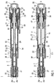
- Figure 1 shows two longitudinal sections in different section planes of an auto-injector 1, the different section planes approximately 90° rotated to each other.
- the auto-injector 1 comprises an elongate housing 2.
- a syringe 3, e.g. a Hypak syringe, with a hollow needle 4 is arranged in a proximal part of the auto-injector 1.
- a protective needle shield 5 is attached to the needle 4.
- a stopper 6 is arranged for sealing the syringe 3 distally and for displacing a liquid medicament M through the hollow needle 4.
- the syringe 3 is held in a tubular syringe carrier 7 and supported at its proximal end therein.
- a single compression spring 8 is arranged in a distal part of the auto-injector 1.
- a plunger 9 is arranged for forwarding the spring force of the compression spring 8.
- a retraction sleeve 10 is slidably arranged inside the housing 2 .
- the retraction sleeve 10 Before the injection is triggered as shown in figure 1 the retraction sleeve 10 is in a maximum proximal position and prevented from moving in distal direction D by means of stops 11 caught behind latches 12 in the housing 2.
- a distal end of the compression spring 8 bears against an end face 13 of the retraction sleeve 10. Due to the stops 11 and latches 12 the force of the compression spring 8 is thus reacted into the housing 2.
- the proximal end of the compression spring 8 bears against a decoupling member 14 arranged around the plunger 9.
- the retraction sleeve Distally from the end face 13 the retraction sleeve has two or more resilient arms 15 for holding a stud 16 and keeping it from being moved in proximal direction P.
- the stud 16 is arranged at the distal end of the plunger 9.
- the stud 16 and the resilient arms 15 have corresponding ramp features for pushing the resilient arms 15 apart in order to allow the stud 16 and the plunger 9 to move in proximal direction P.
- the decoupling member 14 comprises a thrust face 17 for bearing against a proximal end of the compression spring 8. Proximally from the thrust face 17 two or more resilient decoupling arms 18 are provided at the decoupling member 14, the decoupling arms 18 having inner ramped surfaces bearing against a first shoulder 19 in the plunger 9 in proximal direction P.
- the resilient decoupling arms 18 are supported by an inner wall of the retraction sleeve 10 in this situation so they cannot flex outward and slip past the first shoulder 19.
- a trigger button 20 is arranged at the distal end D of the auto-injector 1.
- the trigger button 20 may be pushed in proximal direction P in order to start an injection.
- the resilient arms 15 are caught between two or more retainers 21 arranged at the trigger button 20 so the resilient arms 15 cannot flex outward and the stud 16 although proximally biased by the compression spring 8 cannot slip through.
- the syringe carrier 7 is engaged for joint axial movement with a syringe holder 22 which is slidably arranged in the retraction sleeve 10.
- the syringe holder 22 is provided with two or more resilient syringe holder arms 23 arranged distally.
- the syringe holder arms 23 have a respective inclined surface for bearing against a second shoulder 24 in the plunger 9 arranged proximally from the first shoulder 19. In the initial position shown in figure 1 the syringe holder arms 23 are supported by an inner surface of the housing 2 so they cannot flex outward and the second shoulder 24 cannot slip through.
- a respective number of apertures are provided in the retraction sleeve 10.
- Figure 1 shows the auto-injector 1 as-delivered with a cap 25 screwed onto to the proximal end P of the auto-injector 1.
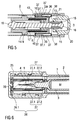
- Figure 6 shows details of the proximal end P with the cap 25.
- the cap 25 comprises a sheet metal clip 26 with two or more barbs 27 extending through an orifice into the proximal end P of the auto-injector 1.
- the sheet metal clip 26 is mounted to the cap 25 for joint axial movement with respect to a longitudinal axis of the auto-injector 1. However, the sheet metal clip 26 may rotate independently from the cap 25.
- the cap 25 is screwed onto the proximal P end of the auto-injector 1 the barbs 27 are pushed down the protective needle shield 5 and snap into a circumferential notch arranged in the protective needle shield 5 or behind a shoulder thereof.
- the first step is to unscrew the cap 25.
- the barbs 27 pull the protective needle shield 5 off the syringe 3 in proximal direction P and through the orifice making the syringe 3 ready to be used.
- a safety button 29 is arranged laterally at the distal part of the housing 2.
- the safety button 29 serves for interlocking with the trigger button 20 in a manner to prevent the trigger button 20 from being inadvertently pushed without the safety button 29 being pushed first.
- the safety button 29 has to be pushed transversally with respect to the longitudinal axis against the force of a spring element 30 which is formed in the safety button 29.
- the safety button 29 is pivoted in the middle so pushing the proximal end of the safety button 29 inward pulls an interlock 31 at its proximal end obstructing the trigger button 20 outward so the trigger button 20 can be pushed.
- the second shoulder 24 pushes the syringe holder 22, syringe carrier 7 and syringe 3 forward while no load is exerted onto the stopper 6.
- the hollow needle 4 appears from the proximal end P and is inserted into an injection site, e.g. a patient's skin.
- the decoupling member 14 When the stopper 6 has nearly bottomed out in the syringe 3 (cf. figure 2 ) the decoupling member 14 has reached a position where its protrusions push against the latches 12 in a manner to decouple the retraction sleeve 10 from the housing 2, so the retraction sleeve 10 may slide in distal direction D.
- the compression spring 8 is no longer grounded with its distal end in the housing 2. Instead, as soon as the decoupling member 14 has bottomed out at a second abutment 33 the proximal end of the compression spring 8 gets grounded in the housing while the distal end is pulling the retraction sleeve 10 in distal direction D.
- the decoupling arms 18 reach an aperture 34 in the retraction sleeve 10 (see fig. 4 ) so they are no longer kept from being flexed outward.
- the decoupling arms 18 are thus pushed outward by the first shoulder 19 pushing against its ramped surfaces so the first shoulder 19 slips through in distal direction as soon as the decoupling member 14 has hit the second abutment 33.
- the syringe holder 22 is taken along in distal direction D by the retraction sleeve 10, e.g. by a front face 35.
- the syringe 3 and needle 4 are retracted into a safe position inside the housing 2, e.g. into the initial position.
- the plunger 9, no longer bearing against the decoupling arms 18 is pulled back too.
- a delay mechanism 36 is arranged (see figure 5 for details).
- the delay mechanism 36 comprises a circumferential outer wall 37 with a back collar 38 attached to the housing 2 and a circumferential inner wall 39 with a front collar 40 attached to the retraction sleeve 10.
- a cavity between the outer wall 37 and inner wall 39 is filled with a viscous fluid, such as silicon grease.
- a viscous fluid such as silicon grease.
- the inner wall 39 glides along the outer wall 37 wherein the back collar 38 and front collar 40 increasingly reduce the volume of the cavity.
- One or more orifices (not shown) provided in a part of the delay mechanism 36 allow the viscous fluid to be pushed out of the cavity as the volume decreases. The force required to do this slows down the motion of the retraction sleeve 10.
- a circumferential shoulder 37.1 is arranged between two portions of the outer wall 37 with the two portions having different cross sections.
- the cavity is sealed by the front collar 40 only until the front collar 40 reaches the shoulder 37.1.
- the front collar 40 has travelled past the shoulder 37.1 the cavity is rendered untight so the motion of the retraction sleeve 10 continues undamped from this point.
- the retraction sleeve 10 is released by the decoupling member 14 from the housing 2 a certain amount of time or travel before the stopper 6 bottoms out in the syringe 3 so that the apertures 34 of the retraction sleeve 10 and the decoupling arms 18, which are now moving in opposite directions, meet after the stopper 6 and plunger 9 have stopped.
- the motion of the retraction sleeve 10 is slowed down by the delay mechanism 36. Due to a gap 41 between the front face 35 and the syringe holder 22 the retraction sleeve 10 is not yet dragging the syringe back in distal direction D.
- the plunger 9 is still pushing against the stopper 6 and expelling residual medicament M.
- the cap 25 and the delay mechanism 36 are not restricted to be used with the auto-injector 1 shown in the embodiments. Instead the cap 25 may be combined with any kind of auto-injector with the needle hidden in the housing prior to an injection.
- the delay mechanism (36) may be combined with any kind of auto-injector for ensuring full delivery of the syringe's contents and reliable triggering of the retraction, irrespective of the spring means or driving means used in the respective auto-injector.
- the housing 2 may have at least one viewing window for inspecting the syringe 3.
- the auto-injector 1 may preferably be used for delivering one of an analgetic, an anticoagulant, insulin, an insulin derivate, heparin, Lovenox, a vaccine, a growth hormone, a peptide hormone, a proteine, antibodies and complex carbohydrates.
- the delay mechanism 36 may also be employed with other types of auto-injectors. However, the delay mechanism 36 is not restricted to use with auto-injectors. It may be likewise used with other mechanical equipment.
- the aforementioned arrangement for coupling the plunger (9) to either, the syringe (3) or the stopper (6), may be applied in any auto-injector having a plunger for forwarding a force of a drive means to a syringe with a stopper.
- the primary advantage of this arrangement ensures the load from the drive means is not transferred directly to the stopper until the needle is inserted in the patient, thus avoiding a wet injection.
- the arrangement comprises the syringe holder (22) and associated syringe holder arms (23), a shoulder (e.g.
- the spring means or other drive means the ability to retract the syringe or to forward a needle shroud after injection and other features described herein are not required for the prevention of a wet injection.
Landscapes
- Health & Medical Sciences (AREA)
- Engineering & Computer Science (AREA)
- Hematology (AREA)
- Anesthesiology (AREA)
- Biomedical Technology (AREA)
- Heart & Thoracic Surgery (AREA)
- Vascular Medicine (AREA)
- Life Sciences & Earth Sciences (AREA)
- Animal Behavior & Ethology (AREA)
- General Health & Medical Sciences (AREA)
- Public Health (AREA)
- Veterinary Medicine (AREA)
- Environmental & Geological Engineering (AREA)
- Infusion, Injection, And Reservoir Apparatuses (AREA)
Claims (11)
- Autoinjektor (1) zum Verabreichen einer Dosis eines flüssigen Medikaments (M), umfassend:- ein längliches Gehäuse (2), gestaltet zum Enthalten einer Spritze (3) mit einer Hohlnadel (4) und einem Stopfen (6) zum Abdichten der Spritze (3) und Verdrängen des Medikaments (M), wobei das Gehäuse (2) ein distales Ende (D) und ein proximales Ende (P) mit einer Öffnung aufweist, die dafür vorgesehen ist, an einen Injektionsort angelegt zu werden, wobei die Spritze (3) verschiebbar bezogen auf das Gehäuse (2) angeordnet ist,- Antriebsmittel (8), die fähig sind, bei Aktivierung:- die Nadel (4) über einen Kolben (9) aus einer verdeckten Position im Inneren des Gehäuses (2) in eine vorgeschobene Position durch die Öffnung und über das proximale Ende (P) hinaus zu schieben,- die Spritze (3) über den Kolben (9) zu betätigen, um die Dosis des Medikaments (M) zu verabreichen, und- nach dem Verabreichen des Medikaments (M) die Spritze (3) mit der Nadel (4) in die verdeckte Position zurückzuziehen,- eine Rückziehhülse (10), die in dem Gehäuse (2) axial beweglich angeordnet ist,- wenigstens einen Riegel (12) zum axialen Fixieren der Rückziehhülse (10) in einer maximal proximalen Position,- einen Verzögerungsmechanismus (36) zum Verlangsamen der Bewegung der Rückziehhülse (10) in distaler Richtung, wobei der Verzögerungsmechanismus (36) eine umlaufende Außenwand (37) mit einem an dem Gehäuse (2) befestigten hinteren Kragen (38) und eine umlaufende Innenwand (39) mit einem an der Rückziehhülse (10) befestigten vorderen Kragen (40) umfasst, wobei ein Hohlraum zwischen der Außenwand (37) und der Innenwand (39) definiert ist, wobei der Hohlraum durch den hinteren Kragen (38) gegen die Innenwand (39) und durch den vorderen Kragen (40) gegen die Außenwand (37) abgedichtet ist, wobei der Hohlraum mit einem viskosen Fluid gefüllt ist, wobei in dem Verzögerungsmechanismus (36) wenigstens eine Öffnung angeordnet ist, um zu erlauben, dass das viskose Fluid hinausgedrückt wird, wenn das Volumen des Hohlraums durch axiale Bewegung der Rückziehhülse (10) bezogen auf das Gehäuse (2) abnimmt, wobei wenigstens eine Öffnung (34) in der Rückziehhülse (10) angeordnet ist,wobei die Riegel (12) gestaltet sind, durch das Entkopplungselement (14) gelöst zu werden, bevor der Stopfen (6) eine maximal proximale Position in der Spritze (3) erreicht hat, wenn er in proximale Richtung bewegt wird, wobei die Öffnungen (34) gestaltet sind, mit den Entkopplungsarmen (18) zusammenzutreffen, nachdem der Stopfen (6) durch die Bewegung der Rückziehhülse (10) seine maximal proximale Position erreicht hat, wobei ein Entkopplungselement (14) gestaltet ist, den Riegel (12) zu entkoppeln, wenn es in proximale Richtung (P) nahezu in eine maximal proximale Position bewegt wird, so dass ermöglicht wird, dass sich die Rückziehhülse (10) in die distale Richtung (D) bewegt und die Nadel (4) zurückzieht, wobei die Öffnung (34) gestaltet ist, zu erlauben, dass ein entsprechender Entkopplungsarm (18) des Entkopplungselements (14) nach außen gebogen wird, dadurch gekennzeichnet, dass eine Lücke (41) zwischen einer Vorderfläche (35) der Rückziehhülse (10) und einem Spritzenhalter (22) in ihren jeweiligen maximal proximalen Positionen besteht, wobei die Spritze (4) für die gemeinsame axiale Bewegung mit dem Spritzenhalter angeordnet ist, wobei die Lücke (41) gestaltet ist, zu erlauben, dass sich die Rückziehhülse (10) über einen Abstand bewegt, bevor sie den Spritzenhalter (22) zurückzieht, so dass der Spritzenhalter (22) zurückgezogen wird, nachdem die Entkopplungsarme (18) auf die Öffnungen (34) getroffen sind, wobei eine umlaufende Schulter zwischen zwei Teilen von wenigstens einer von der Innenwand und der Außenwand angeordnet ist, wobei die beiden Teile auf eine solche Weise unterschiedliche Querschnitte aufweisen, dass der Hohlraum von dem entsprechenden Kragen (38, 40) nur so lange abgedichtet wird, bis der Kragen (38, 40) die Schulter erreicht und der Hohlraum undicht gemacht wird, wenn sich der Kragen (38, 40) über die Schulter hinaus bewegt hat.
- Autoinjektor (1) gemäß Anspruch 1, dadurch gekennzeichnet, dass das viskose Fluid Siliconfett ist.
- Autoinjektor (1) gemäß einem der Ansprüche 1 bis 2, dadurch gekennzeichnet, dass die Antriebsmittel als Federmittel (8) gestaltet sind, wobei Aktivierungsmittel (20) ausgebildet sind, die Federeinrichtung (8) vor einer manuellen Betätigung in einem druckbeaufschlagten Zustand zu verriegeln, und fähig sind, bei manueller Betätigung die Federeinrichtung (8) für die Injektion freizugeben.
- Autoinjektor (1) gemäß Anspruch 3, dadurch gekennzeichnet, dass das Federmittel (8) eine einzelne Kompressionsfeder (8) ist, die ausgebildet ist, sich an einem distalen Ende (8.1) in dem Gehäuse (2) zu stützen, um die Nadel (4) vorzuschieben und die Dosis des Medikaments (M) zu injizieren, und wobei die Kompressionsfeder (8) so gestaltet ist, dass zum Zurückziehen der Spritze (3) ihr Stützpunkt in dem Gehäuse (2) an ihr proximales Ende (8.2) umgelegt wird.
- Autoinjektor (1) gemäß Anspruch 4, dadurch gekennzeichnet, dass die Kompressionsfeder (8) im Inneren der Rückziehhülse (10) angeordnet ist, wobei sich ihr distales Ende gegen eine distale Endfläche (13) stützt und sich ihr proximales Ende gegen eine Druckfläche (17) des Entkopplungselements (14) stützt.
- Autoinjektor (1) gemäß einem der Ansprüche 4 oder 5, dadurch gekennzeichnet, dass die Entkopplungsarme (18) innere abgeschrägte Oberflächen aufweisen, die sich gegen eine erste Schulter (19) des Kolbens (9) in proximaler Richtung (P) stützen, wobei die elastischen Entkopplungsarme (18) von einer Innenwand der Rückziehhülse (10) gehalten werden können, um zu verhindern, dass die Entkopplungsarme (18) nach außen gebogen werden und über die erste Schulter (19) hinaus gleiten, und die Öffnung (34) in der Rückziehhülse (10) erlaubt, dass die Entkopplungsarme (18) durch die erste Schulter (19) nach außen gebogen werden, und so erlaubt, dass die erste Schulter (19) in proximaler Richtung (P) durch die Entkopplungsarme (18) gleitet, wobei der Kolben (9) gestaltet ist, die Spritze (3) und/oder den Stopfen (6) in die proximale Richtung (P) zu drücken.
- Autoinjektor (1) gemäß Anspruch 6, dadurch gekennzeichnet, dass der Spritzenhalter (22) verschiebbar in der Rückziehhülse (10) angeordnet ist, wobei der Spritzenhalter (22) mit wenigstens zwei distal angeordneten elastischen Spritzenhalterarmen (23) versehen ist, wobei die Spritzenhalterarme (23) eine entsprechende schräge Oberfläche aufweisen, um sich gegen eine zweite Schulter (24) zu stützen, die an dem Kolben (9) proximal bezogen auf die erste Schulter (19) angeordnet ist, wobei die Spritzenhalterarme (23) von einer Innenoberfläche des Gehäuses (2) gehalten werden können, um zu verhindern, dass sie nach außen gebogen werden, und wobei in dem Gehäuse (2) ein geweiteter Teil (2.1) vorhanden ist, um zu erlauben, dass sich die Spritzenhalterarme (23) nach außen biegen, wenn der Spritzenhalter (22) beinahe eine maximal proximale Position erreicht hat, und so zu erlauben, dass die zweite Schulter (24) durch die Spritzenhalterarme (23) gleitet und die Last der Kompressionsfeder (8) von der Spritze (3) auf den Stopfen (6) umschaltet.
- Autoinjektor (1) gemäß einem der Ansprüche 5 bis 7, dadurch gekennzeichnet, dass ein Buckel (16) an dem distalen Ende des Kolbens (9) angeordnet ist, wobei die Rückziehhülse (10) zwei oder mehr elastische Arme (15) distal von der Endfläche (13) zum Festhalten des Buckels (16) aufweist, wobei der Buckel (16) und/oder die elastischen Arme (15) Rampeneinrichtungen aufweisen, so dass die elastischen Arme (15) von dem Buckel (16) auseinandergedrückt werden können, wenn der Kolben (9) in die proximale Richtung (P) bewegt wird, wobei die Aktivierungsmittel einen Auslöseknopf (20) umfassen, der an dem distalen Ende (D) des Autoinjektors (1) angeordnet ist, wobei der Auslöseknopf (20) axial beweglich ist und wenigstens zwei starre Rückhalteelemente (21) aufweist, um zu verhindern, dass die elastischen Arme (15) nach außen gebogen werden, wenn sich der Auslöseknopf (20) in einer maximal distalen Position befindet, und wobei bei Drücken des Auslöseknopfs (20) in die proximale Richtung (P) die Rückhalteelemente (21) auf eine Weise in die proximale Richtung (P) bewegt werden, die erlaubt, dass die elastischen Arme (15) von dem Buckel (16), der von der Kompressionsfeder (8) in die proximale Richtung vorgespannt ist, nach außen gebogen werden, so dass ermöglicht wird, dass der Buckel (16) über die elastischen Arme (15) hinaus in die proximale Richtung (P) gleitet.
- Autoinjektor (1) gemäß Anspruch 8, dadurch gekennzeichnet, dass ein Sicherheitsknopf (29) seitlich an dem Gehäuse (2) angeordnet ist, wobei der Sicherheitsknopf (29) eine Sperre (31) aufweist, um zu verhindern, dass der Auslöseknopf (20) gedrückt wird, wobei der Sicherheitsknopf (29) gestaltet ist, die Sperre (31) nach außen zu ziehen, wenn er betätigt wird, und so zu erlauben, dass der Auslöseknopf (20) gedrückt wird.
- Autoinjektor (1) gemäß einem der Ansprüche 1 bis 9, dadurch gekennzeichnet, dass an dem proximalen Ende (P) des Gehäuses (2) eine Kappe (25) bereitgestellt ist, wobei an der Kappe (25) ein Flachmetallclip (26) für die gemeinsame axiale Bewegung und unabhängige Drehung angebracht ist, wobei der Flachmetallclip (26) gestaltet ist, durch eine Öffnung in das Gehäuse (2) zu ragen, wenn die Kappe (25) an dem Gehäuse (2) angebracht ist, wobei der Flachmetallclip (26) wenigstens zwei Widerhaken (27) aufweist, die in eine umlaufende Rille oder hinter eine Schulter eines an der Hohlnadel (4) angebrachten schützenden Nadelschutzschilds (5) eingeschnappt sind.
- Autoinjektor (1) gemäß Anspruch 10, dadurch gekennzeichnet, dass die Kappe (25) durch eine Schraubverbindung an dem Gehäuse (2) angebracht werden kann.
Priority Applications (1)
| Application Number | Priority Date | Filing Date | Title |
|---|---|---|---|
| EP11704219.2A EP2536454B1 (de) | 2010-02-18 | 2011-02-16 | Autoinjektor mit Verzögerungsmechanismus |
Applications Claiming Priority (3)
| Application Number | Priority Date | Filing Date | Title |
|---|---|---|---|
| EP10154003 | 2010-02-18 | ||
| PCT/EP2011/052302 WO2011101380A1 (en) | 2010-02-18 | 2011-02-16 | Auto-injector |
| EP11704219.2A EP2536454B1 (de) | 2010-02-18 | 2011-02-16 | Autoinjektor mit Verzögerungsmechanismus |
Publications (2)
| Publication Number | Publication Date |
|---|---|
| EP2536454A1 EP2536454A1 (de) | 2012-12-26 |
| EP2536454B1 true EP2536454B1 (de) | 2016-08-03 |
Family
ID=42262121
Family Applications (1)
| Application Number | Title | Priority Date | Filing Date |
|---|---|---|---|
| EP11704219.2A Active EP2536454B1 (de) | 2010-02-18 | 2011-02-16 | Autoinjektor mit Verzögerungsmechanismus |
Country Status (6)
| Country | Link |
|---|---|
| US (1) | US8911410B2 (de) |
| EP (1) | EP2536454B1 (de) |
| JP (1) | JP5807022B2 (de) |
| CA (1) | CA2790188A1 (de) |
| DK (1) | DK2536454T3 (de) |
| WO (1) | WO2011101380A1 (de) |
Families Citing this family (51)
| Publication number | Priority date | Publication date | Assignee | Title |
|---|---|---|---|---|
| CA2475573C (en) | 2002-02-11 | 2013-03-26 | Antares Pharma, Inc. | Intradermal injector |
| CN101132820B (zh) | 2005-01-24 | 2010-05-19 | 安塔雷斯制药公司 | 预充式针辅助喷射注入器 |
| WO2007131013A1 (en) | 2006-05-03 | 2007-11-15 | Antares Pharma, Inc. | Two-stage reconstituting injector |
| US9144648B2 (en) | 2006-05-03 | 2015-09-29 | Antares Pharma, Inc. | Injector with adjustable dosing |
| US9173997B2 (en) | 2007-10-02 | 2015-11-03 | Medimop Medical Projects Ltd. | External drug pump |
| EP2990067B1 (de) | 2008-03-10 | 2019-09-04 | Antares Pharma, Inc. | Injektorsicherheitsvorrichtung |
| US9974904B2 (en) | 2008-05-20 | 2018-05-22 | Avant Medical Corp. | Autoinjector system |
| US8177749B2 (en) | 2008-05-20 | 2012-05-15 | Avant Medical Corp. | Cassette for a hidden injection needle |
| US8052645B2 (en) | 2008-07-23 | 2011-11-08 | Avant Medical Corp. | System and method for an injection using a syringe needle |
| EP3581224A1 (de) | 2008-08-05 | 2019-12-18 | Antares Pharma, Inc. | Injektor mit mehrfachdosierung |
| CA2790193A1 (en) | 2010-02-18 | 2011-08-25 | Sanofi-Aventis Deutschland Gmbh | Auto-injector |
| US9084849B2 (en) | 2011-01-26 | 2015-07-21 | Kaleo, Inc. | Medicament delivery devices for administration of a medicament within a prefilled syringe |
| HUE042822T2 (hu) | 2011-04-20 | 2019-07-29 | Amgen Inc | Automata befecskendezõ szerkezet |
| US9220660B2 (en) | 2011-07-15 | 2015-12-29 | Antares Pharma, Inc. | Liquid-transfer adapter beveled spike |
| US8496619B2 (en) | 2011-07-15 | 2013-07-30 | Antares Pharma, Inc. | Injection device with cammed ram assembly |
| EP2596823A1 (de) * | 2011-11-24 | 2013-05-29 | Sanofi-Aventis Deutschland GmbH | Autoinjektor |
| HUE066117T2 (hu) | 2012-03-06 | 2024-07-28 | Antares Pharma Inc | Elõretöltött fecskendõ szakítóerõ-funkcióval |
| JP6457383B2 (ja) | 2012-04-06 | 2019-01-23 | アンタレス・ファーマ・インコーポレーテッド | テストステロン組成物の針支援式ジェット注入投与 |
| USD898908S1 (en) | 2012-04-20 | 2020-10-13 | Amgen Inc. | Pharmaceutical product cassette for an injection device |
| US9364610B2 (en) | 2012-05-07 | 2016-06-14 | Antares Pharma, Inc. | Injection device with cammed ram assembly |
| US9707357B2 (en) | 2012-05-25 | 2017-07-18 | Aptar France Sas | Autoinjector |
| US9707343B2 (en) | 2012-05-25 | 2017-07-18 | Aptar France Sas | Autoinjector comprising a time delay device having a planetary gear set for delaying the retraction of the needle |
| US9717851B2 (en) | 2012-05-25 | 2017-08-01 | Aptar France Sas | Autoinjector |
| WO2013175140A1 (fr) | 2012-05-25 | 2013-11-28 | Aptar France Sas | Autoinjecteur |
| FR2990866B1 (fr) * | 2012-05-25 | 2015-04-24 | Valois Sas | Autoinjecteur |
| IN2015DN01589A (de) | 2012-09-27 | 2015-07-03 | Aptar France Sas | |
| EP4349383A3 (de) | 2013-02-11 | 2024-06-19 | Antares Pharma, Inc. | Nadelunterstützte strahlinjektionsvorrichtung mit reduzierter auslöserkraft |
| EP2968792B1 (de) | 2013-03-11 | 2019-05-15 | Antares Pharma, Inc. | Dosierungsinjektor mit einem zahnradsystem |
| TWI614041B (zh) | 2013-03-15 | 2018-02-11 | 安美基公司 | 用於注射器之匣盒 |
| JP6336564B2 (ja) | 2013-03-15 | 2018-06-06 | アムゲン・インコーポレーテッド | 薬物カセット、自動注入器、および自動注入器システム |
| GB2516624B (en) * | 2013-07-25 | 2018-09-19 | Owen Mumford Ltd | Injection devices |
| US9517307B2 (en) | 2014-07-18 | 2016-12-13 | Kaleo, Inc. | Devices and methods for delivering opioid antagonists including formulations for naloxone |
| FR3036966B1 (fr) * | 2015-06-05 | 2021-10-01 | Aptar France Sas | Autoinjecteur |
| US10576206B2 (en) | 2015-06-30 | 2020-03-03 | Kaleo, Inc. | Auto-injectors for administration of a medicament within a prefilled syringe |
| US10576207B2 (en) | 2015-10-09 | 2020-03-03 | West Pharma. Services IL, Ltd. | Angled syringe patch injector |
| JP7044708B2 (ja) | 2015-10-09 | 2022-03-30 | ウェスト ファーマ サービシーズ イスラエル リミテッド | カスタマイズシリンジの充填方法 |
| CN109219456B (zh) | 2016-01-21 | 2020-05-15 | 西医药服务以色列有限公司 | 自动注射器中的力牵制 |
| WO2017127215A1 (en) | 2016-01-21 | 2017-07-27 | Medimop Medical Projects Ltd. | Needle insertion and retraction mechanism |
| CN113041432B (zh) | 2016-01-21 | 2023-04-07 | 西医药服务以色列有限公司 | 包括视觉指示物的药剂输送装置 |
| EP3427244B1 (de) | 2016-03-07 | 2020-09-09 | SHL Medical AG | Automatische injektionstrainingsvorrichtung |
| US11389597B2 (en) | 2016-03-16 | 2022-07-19 | West Pharma. Services IL, Ltd. | Staged telescopic screw assembly having different visual indicators |
| GB201607491D0 (en) * | 2016-04-29 | 2016-06-15 | Owen Mumford Ltd | Injection devices |
| US11730892B2 (en) | 2016-08-01 | 2023-08-22 | West Pharma. Services IL, Ltd. | Partial door closure prevention spring |
| US11338090B2 (en) | 2016-08-01 | 2022-05-24 | West Pharma. Services IL, Ltd. | Anti-rotation cartridge pin |
| EP3558420B1 (de) | 2016-12-23 | 2024-09-18 | Kaleo, Inc. | Medikamentenabgabevorrichtung und verfahren zur abgabe von arzneimitteln an säuglinge und kinder |
| EP3630226B1 (de) | 2017-05-30 | 2025-10-22 | West Pharma. Services Il, Ltd. | Modularer antriebsstrang für am körper tragbaren injektor |
| US12569620B2 (en) | 2018-01-19 | 2026-03-10 | Birya Biotech, Inc. | Tool for servicing an auto-injector |
| EP3902584A4 (de) | 2018-12-29 | 2022-09-07 | Kaleo, Inc. | Vorrichtungen und verfahren zur abgabe von substanzen in einer vorgefüllten spritze |
| CA3145580A1 (en) | 2019-08-09 | 2021-02-18 | Kaleo, Inc. | Devices and methods for delivery of substances within a prefilled syringe |
| GB2596600A (en) * | 2020-07-03 | 2022-01-05 | Consort Medical Ltd | A sealable joint |
| US12268847B1 (en) | 2021-02-10 | 2025-04-08 | Kaleo, Inc. | Devices and methods for delivery of substances within a medicament container |
Family Cites Families (8)
| Publication number | Priority date | Publication date | Assignee | Title |
|---|---|---|---|---|
| AU2001281753A1 (en) | 2000-08-29 | 2002-03-13 | Novo-Nordisk A/S | Automatic injection device with torsion function for retraction of needle |
| GB0211294D0 (en) | 2002-05-17 | 2002-06-26 | Owen Mumford Ltd | Improvements relating to injection devices |
| GB2396816A (en) * | 2002-12-17 | 2004-07-07 | Pa Consulting Services | Injection device |
| US20050027255A1 (en) | 2003-07-31 | 2005-02-03 | Sid Technologies, Llc | Automatic injector |
| GB2414399B (en) * | 2004-05-28 | 2008-12-31 | Cilag Ag Int | Injection device |
| GB2424838B (en) * | 2005-04-06 | 2011-02-23 | Cilag Ag Int | Injection device (adaptable drive) |
| FR2905273B1 (fr) * | 2006-09-06 | 2009-04-03 | Becton Dickinson France Soc Pa | Dispositif d'injection automatique avec moyen de temporisation. |
| CN102099069B (zh) | 2008-05-20 | 2013-11-27 | Shl集团有限责任公司 | 用于药物输送装置的装置 |
-
2011
- 2011-02-16 JP JP2012553304A patent/JP5807022B2/ja active Active
- 2011-02-16 EP EP11704219.2A patent/EP2536454B1/de active Active
- 2011-02-16 CA CA2790188A patent/CA2790188A1/en not_active Abandoned
- 2011-02-16 DK DK11704219.2T patent/DK2536454T3/en active
- 2011-02-16 US US13/579,450 patent/US8911410B2/en active Active
- 2011-02-16 WO PCT/EP2011/052302 patent/WO2011101380A1/en not_active Ceased
Also Published As
| Publication number | Publication date |
|---|---|
| US8911410B2 (en) | 2014-12-16 |
| JP5807022B2 (ja) | 2015-11-10 |
| CA2790188A1 (en) | 2011-08-25 |
| EP2536454A1 (de) | 2012-12-26 |
| DK2536454T3 (en) | 2016-11-28 |
| JP2013519475A (ja) | 2013-05-30 |
| US20130172822A1 (en) | 2013-07-04 |
| WO2011101380A1 (en) | 2011-08-25 |
Similar Documents
| Publication | Publication Date | Title |
|---|---|---|
| US12582774B2 (en) | Auto-injector | |
| EP2536454B1 (de) | Autoinjektor mit Verzögerungsmechanismus |
Legal Events
| Date | Code | Title | Description |
|---|---|---|---|
| PUAI | Public reference made under article 153(3) epc to a published international application that has entered the european phase |
Free format text: ORIGINAL CODE: 0009012 |
|
| 17P | Request for examination filed |
Effective date: 20120918 |
|
| AK | Designated contracting states |
Kind code of ref document: A1 Designated state(s): AL AT BE BG CH CY CZ DE DK EE ES FI FR GB GR HR HU IE IS IT LI LT LU LV MC MK MT NL NO PL PT RO RS SE SI SK SM TR |
|
| AX | Request for extension of the european patent |
Extension state: BA ME |
|
| 17Q | First examination report despatched |
Effective date: 20140303 |
|
| REG | Reference to a national code |
Ref country code: DE Ref legal event code: R079 Ref document number: 602011028770 Country of ref document: DE Free format text: PREVIOUS MAIN CLASS: A61M0005200000 Ipc: A61M0005320000 |
|
| GRAP | Despatch of communication of intention to grant a patent |
Free format text: ORIGINAL CODE: EPIDOSNIGR1 |
|
| RIC1 | Information provided on ipc code assigned before grant |
Ipc: A61M 5/20 20060101ALI20160316BHEP Ipc: A61M 5/32 20060101AFI20160316BHEP |
|
| INTG | Intention to grant announced |
Effective date: 20160408 |
|
| GRAS | Grant fee paid |
Free format text: ORIGINAL CODE: EPIDOSNIGR3 |
|
| GRAA | (expected) grant |
Free format text: ORIGINAL CODE: 0009210 |
|
| AK | Designated contracting states |
Kind code of ref document: B1 Designated state(s): AL AT BE BG CH CY CZ DE DK EE ES FI FR GB GR HR HU IE IS IT LI LT LU LV MC MK MT NL NO PL PT RO RS SE SI SK SM TR |
|
| AX | Request for extension of the european patent |
Extension state: BA ME |
|
| REG | Reference to a national code |
Ref country code: GB Ref legal event code: FG4D |
|
| REG | Reference to a national code |
Ref country code: CH Ref legal event code: EP Ref country code: AT Ref legal event code: REF Ref document number: 816944 Country of ref document: AT Kind code of ref document: T Effective date: 20160815 |
|
| REG | Reference to a national code |
Ref country code: IE Ref legal event code: FG4D |
|
| REG | Reference to a national code |
Ref country code: DE Ref legal event code: R096 Ref document number: 602011028770 Country of ref document: DE |
|
| REG | Reference to a national code |
Ref country code: SE Ref legal event code: TRGR |
|
| REG | Reference to a national code |
Ref country code: DK Ref legal event code: T3 Effective date: 20161121 |
|
| REG | Reference to a national code |
Ref country code: NL Ref legal event code: MP Effective date: 20160803 |
|
| REG | Reference to a national code |
Ref country code: LT Ref legal event code: MG4D |
|
| REG | Reference to a national code |
Ref country code: FR Ref legal event code: PLFP Year of fee payment: 7 |
|
| REG | Reference to a national code |
Ref country code: AT Ref legal event code: MK05 Ref document number: 816944 Country of ref document: AT Kind code of ref document: T Effective date: 20160803 |
|
| PG25 | Lapsed in a contracting state [announced via postgrant information from national office to epo] |
Ref country code: NO Free format text: LAPSE BECAUSE OF FAILURE TO SUBMIT A TRANSLATION OF THE DESCRIPTION OR TO PAY THE FEE WITHIN THE PRESCRIBED TIME-LIMIT Effective date: 20161103 Ref country code: FI Free format text: LAPSE BECAUSE OF FAILURE TO SUBMIT A TRANSLATION OF THE DESCRIPTION OR TO PAY THE FEE WITHIN THE PRESCRIBED TIME-LIMIT Effective date: 20160803 Ref country code: IT Free format text: LAPSE BECAUSE OF FAILURE TO SUBMIT A TRANSLATION OF THE DESCRIPTION OR TO PAY THE FEE WITHIN THE PRESCRIBED TIME-LIMIT Effective date: 20160803 Ref country code: RS Free format text: LAPSE BECAUSE OF FAILURE TO SUBMIT A TRANSLATION OF THE DESCRIPTION OR TO PAY THE FEE WITHIN THE PRESCRIBED TIME-LIMIT Effective date: 20160803 Ref country code: LT Free format text: LAPSE BECAUSE OF FAILURE TO SUBMIT A TRANSLATION OF THE DESCRIPTION OR TO PAY THE FEE WITHIN THE PRESCRIBED TIME-LIMIT Effective date: 20160803 Ref country code: NL Free format text: LAPSE BECAUSE OF FAILURE TO SUBMIT A TRANSLATION OF THE DESCRIPTION OR TO PAY THE FEE WITHIN THE PRESCRIBED TIME-LIMIT Effective date: 20160803 Ref country code: IS Free format text: LAPSE BECAUSE OF FAILURE TO SUBMIT A TRANSLATION OF THE DESCRIPTION OR TO PAY THE FEE WITHIN THE PRESCRIBED TIME-LIMIT Effective date: 20161203 Ref country code: HR Free format text: LAPSE BECAUSE OF FAILURE TO SUBMIT A TRANSLATION OF THE DESCRIPTION OR TO PAY THE FEE WITHIN THE PRESCRIBED TIME-LIMIT Effective date: 20160803 |
|
| PG25 | Lapsed in a contracting state [announced via postgrant information from national office to epo] |
Ref country code: LV Free format text: LAPSE BECAUSE OF FAILURE TO SUBMIT A TRANSLATION OF THE DESCRIPTION OR TO PAY THE FEE WITHIN THE PRESCRIBED TIME-LIMIT Effective date: 20160803 Ref country code: PT Free format text: LAPSE BECAUSE OF FAILURE TO SUBMIT A TRANSLATION OF THE DESCRIPTION OR TO PAY THE FEE WITHIN THE PRESCRIBED TIME-LIMIT Effective date: 20161205 Ref country code: ES Free format text: LAPSE BECAUSE OF FAILURE TO SUBMIT A TRANSLATION OF THE DESCRIPTION OR TO PAY THE FEE WITHIN THE PRESCRIBED TIME-LIMIT Effective date: 20160803 Ref country code: PL Free format text: LAPSE BECAUSE OF FAILURE TO SUBMIT A TRANSLATION OF THE DESCRIPTION OR TO PAY THE FEE WITHIN THE PRESCRIBED TIME-LIMIT Effective date: 20160803 Ref country code: GR Free format text: LAPSE BECAUSE OF FAILURE TO SUBMIT A TRANSLATION OF THE DESCRIPTION OR TO PAY THE FEE WITHIN THE PRESCRIBED TIME-LIMIT Effective date: 20161104 Ref country code: AT Free format text: LAPSE BECAUSE OF FAILURE TO SUBMIT A TRANSLATION OF THE DESCRIPTION OR TO PAY THE FEE WITHIN THE PRESCRIBED TIME-LIMIT Effective date: 20160803 |
|
| PG25 | Lapsed in a contracting state [announced via postgrant information from national office to epo] |
Ref country code: EE Free format text: LAPSE BECAUSE OF FAILURE TO SUBMIT A TRANSLATION OF THE DESCRIPTION OR TO PAY THE FEE WITHIN THE PRESCRIBED TIME-LIMIT Effective date: 20160803 Ref country code: RO Free format text: LAPSE BECAUSE OF FAILURE TO SUBMIT A TRANSLATION OF THE DESCRIPTION OR TO PAY THE FEE WITHIN THE PRESCRIBED TIME-LIMIT Effective date: 20160803 |
|
| PGFP | Annual fee paid to national office [announced via postgrant information from national office to epo] |
Ref country code: MC Payment date: 20170103 Year of fee payment: 7 |
|
| REG | Reference to a national code |
Ref country code: DE Ref legal event code: R097 Ref document number: 602011028770 Country of ref document: DE |
|
| PG25 | Lapsed in a contracting state [announced via postgrant information from national office to epo] |
Ref country code: CZ Free format text: LAPSE BECAUSE OF FAILURE TO SUBMIT A TRANSLATION OF THE DESCRIPTION OR TO PAY THE FEE WITHIN THE PRESCRIBED TIME-LIMIT Effective date: 20160803 Ref country code: BG Free format text: LAPSE BECAUSE OF FAILURE TO SUBMIT A TRANSLATION OF THE DESCRIPTION OR TO PAY THE FEE WITHIN THE PRESCRIBED TIME-LIMIT Effective date: 20161103 Ref country code: BE Free format text: LAPSE BECAUSE OF FAILURE TO SUBMIT A TRANSLATION OF THE DESCRIPTION OR TO PAY THE FEE WITHIN THE PRESCRIBED TIME-LIMIT Effective date: 20160803 Ref country code: SM Free format text: LAPSE BECAUSE OF FAILURE TO SUBMIT A TRANSLATION OF THE DESCRIPTION OR TO PAY THE FEE WITHIN THE PRESCRIBED TIME-LIMIT Effective date: 20160803 Ref country code: SK Free format text: LAPSE BECAUSE OF FAILURE TO SUBMIT A TRANSLATION OF THE DESCRIPTION OR TO PAY THE FEE WITHIN THE PRESCRIBED TIME-LIMIT Effective date: 20160803 |
|
| PGFP | Annual fee paid to national office [announced via postgrant information from national office to epo] |
Ref country code: IE Payment date: 20170209 Year of fee payment: 7 Ref country code: LU Payment date: 20170204 Year of fee payment: 7 Ref country code: BE Payment date: 20161228 Year of fee payment: 7 Ref country code: NL Payment date: 20170210 Year of fee payment: 7 |
|
| PLBE | No opposition filed within time limit |
Free format text: ORIGINAL CODE: 0009261 |
|
| STAA | Information on the status of an ep patent application or granted ep patent |
Free format text: STATUS: NO OPPOSITION FILED WITHIN TIME LIMIT |
|
| 26N | No opposition filed |
Effective date: 20170504 |
|
| PG25 | Lapsed in a contracting state [announced via postgrant information from national office to epo] |
Ref country code: SI Free format text: LAPSE BECAUSE OF FAILURE TO SUBMIT A TRANSLATION OF THE DESCRIPTION OR TO PAY THE FEE WITHIN THE PRESCRIBED TIME-LIMIT Effective date: 20160803 |
|
| REG | Reference to a national code |
Ref country code: FR Ref legal event code: PLFP Year of fee payment: 8 |
|
| PG25 | Lapsed in a contracting state [announced via postgrant information from national office to epo] |
Ref country code: MC Free format text: LAPSE BECAUSE OF NON-PAYMENT OF DUE FEES Effective date: 20180228 |
|
| PGFP | Annual fee paid to national office [announced via postgrant information from national office to epo] |
Ref country code: MT Payment date: 20170216 Year of fee payment: 7 |
|
| PG25 | Lapsed in a contracting state [announced via postgrant information from national office to epo] |
Ref country code: AL Free format text: LAPSE BECAUSE OF FAILURE TO SUBMIT A TRANSLATION OF THE DESCRIPTION OR TO PAY THE FEE WITHIN THE PRESCRIBED TIME-LIMIT Effective date: 20160803 |
|
| REG | Reference to a national code |
Ref country code: IE Ref legal event code: MM4A |
|
| PG25 | Lapsed in a contracting state [announced via postgrant information from national office to epo] |
Ref country code: LU Free format text: LAPSE BECAUSE OF NON-PAYMENT OF DUE FEES Effective date: 20180216 |
|
| PG25 | Lapsed in a contracting state [announced via postgrant information from national office to epo] |
Ref country code: IE Free format text: LAPSE BECAUSE OF NON-PAYMENT OF DUE FEES Effective date: 20180216 |
|
| PGFP | Annual fee paid to national office [announced via postgrant information from national office to epo] |
Ref country code: SE Payment date: 20190212 Year of fee payment: 9 |
|
| PG25 | Lapsed in a contracting state [announced via postgrant information from national office to epo] |
Ref country code: HU Free format text: LAPSE BECAUSE OF FAILURE TO SUBMIT A TRANSLATION OF THE DESCRIPTION OR TO PAY THE FEE WITHIN THE PRESCRIBED TIME-LIMIT; INVALID AB INITIO Effective date: 20110216 |
|
| PG25 | Lapsed in a contracting state [announced via postgrant information from national office to epo] |
Ref country code: CY Free format text: LAPSE BECAUSE OF NON-PAYMENT OF DUE FEES Effective date: 20160803 |
|
| PG25 | Lapsed in a contracting state [announced via postgrant information from national office to epo] |
Ref country code: MK Free format text: LAPSE BECAUSE OF FAILURE TO SUBMIT A TRANSLATION OF THE DESCRIPTION OR TO PAY THE FEE WITHIN THE PRESCRIBED TIME-LIMIT Effective date: 20160803 |
|
| PG25 | Lapsed in a contracting state [announced via postgrant information from national office to epo] |
Ref country code: MT Free format text: LAPSE BECAUSE OF NON-PAYMENT OF DUE FEES Effective date: 20180216 |
|
| REG | Reference to a national code |
Ref country code: SE Ref legal event code: EUG |
|
| PG25 | Lapsed in a contracting state [announced via postgrant information from national office to epo] |
Ref country code: SE Free format text: LAPSE BECAUSE OF NON-PAYMENT OF DUE FEES Effective date: 20200217 |
|
| PG25 | Lapsed in a contracting state [announced via postgrant information from national office to epo] |
Ref country code: TR Free format text: LAPSE BECAUSE OF NON-PAYMENT OF DUE FEES Effective date: 20200216 |
|
| P01 | Opt-out of the competence of the unified patent court (upc) registered |
Effective date: 20230421 |
|
| REG | Reference to a national code |
Ref country code: DE Ref legal event code: R082 Ref document number: 602011028770 Country of ref document: DE |
|
| PGFP | Annual fee paid to national office [announced via postgrant information from national office to epo] |
Ref country code: FR Payment date: 20251208 Year of fee payment: 16 |
|
| REG | Reference to a national code |
Ref country code: CH Ref legal event code: U11 Free format text: ST27 STATUS EVENT CODE: U-0-0-U10-U11 (AS PROVIDED BY THE NATIONAL OFFICE) Effective date: 20260301 |
|
| PGFP | Annual fee paid to national office [announced via postgrant information from national office to epo] |
Ref country code: GB Payment date: 20260106 Year of fee payment: 16 |
|
| PGFP | Annual fee paid to national office [announced via postgrant information from national office to epo] |
Ref country code: DE Payment date: 20251224 Year of fee payment: 16 Ref country code: DK Payment date: 20260213 Year of fee payment: 16 |
|
| PGFP | Annual fee paid to national office [announced via postgrant information from national office to epo] |
Ref country code: CH Payment date: 20260301 Year of fee payment: 16 |