EP2536554B1 - Systeme et procede de fabrication des bandes transporteuses avec armure en acier - Google Patents
Systeme et procede de fabrication des bandes transporteuses avec armure en acier Download PDFInfo
- Publication number
- EP2536554B1 EP2536554B1 EP11704224.2A EP11704224A EP2536554B1 EP 2536554 B1 EP2536554 B1 EP 2536554B1 EP 11704224 A EP11704224 A EP 11704224A EP 2536554 B1 EP2536554 B1 EP 2536554B1
- Authority
- EP
- European Patent Office
- Prior art keywords
- cable
- tensioning
- measuring
- unwinding
- tension
- Prior art date
- Legal status (The legal status is an assumption and is not a legal conclusion. Google has not performed a legal analysis and makes no representation as to the accuracy of the status listed.)
- Active
Links
Images






Classifications
-
- B—PERFORMING OPERATIONS; TRANSPORTING
- B29—WORKING OF PLASTICS; WORKING OF SUBSTANCES IN A PLASTIC STATE IN GENERAL
- B29D—PRODUCING PARTICULAR ARTICLES FROM PLASTICS OR FROM SUBSTANCES IN A PLASTIC STATE
- B29D29/00—Producing belts or bands
- B29D29/06—Conveyor belts
-
- B—PERFORMING OPERATIONS; TRANSPORTING
- B29—WORKING OF PLASTICS; WORKING OF SUBSTANCES IN A PLASTIC STATE IN GENERAL
- B29C—SHAPING OR JOINING OF PLASTICS; SHAPING OF MATERIAL IN A PLASTIC STATE, NOT OTHERWISE PROVIDED FOR; AFTER-TREATMENT OF THE SHAPED PRODUCTS, e.g. REPAIRING
- B29C43/00—Compression moulding, i.e. applying external pressure to flow the moulding material; Apparatus therefor
- B29C43/22—Compression moulding, i.e. applying external pressure to flow the moulding material; Apparatus therefor of articles of indefinite length
- B29C43/28—Compression moulding, i.e. applying external pressure to flow the moulding material; Apparatus therefor of articles of indefinite length incorporating preformed parts or layers, e.g. compression moulding around inserts or for coating articles
-
- B—PERFORMING OPERATIONS; TRANSPORTING
- B65—CONVEYING; PACKING; STORING; HANDLING THIN OR FILAMENTARY MATERIAL
- B65H—HANDLING THIN OR FILAMENTARY MATERIAL, e.g. SHEETS, WEBS, CABLES
- B65H57/00—Guides for filamentary materials; Supports therefor
- B65H57/14—Pulleys, rollers, or rotary bars
-
- B—PERFORMING OPERATIONS; TRANSPORTING
- B65—CONVEYING; PACKING; STORING; HANDLING THIN OR FILAMENTARY MATERIAL
- B65H—HANDLING THIN OR FILAMENTARY MATERIAL, e.g. SHEETS, WEBS, CABLES
- B65H57/00—Guides for filamentary materials; Supports therefor
- B65H57/16—Guides for filamentary materials; Supports therefor formed to maintain a plurality of filaments in spaced relation
-
- B—PERFORMING OPERATIONS; TRANSPORTING
- B65—CONVEYING; PACKING; STORING; HANDLING THIN OR FILAMENTARY MATERIAL
- B65H—HANDLING THIN OR FILAMENTARY MATERIAL, e.g. SHEETS, WEBS, CABLES
- B65H59/00—Adjusting or controlling tension in filamentary material, e.g. for preventing snarling; Applications of tension indicators
- B65H59/02—Adjusting or controlling tension in filamentary material, e.g. for preventing snarling; Applications of tension indicators by regulating delivery of material from supply package
-
- B—PERFORMING OPERATIONS; TRANSPORTING
- B65—CONVEYING; PACKING; STORING; HANDLING THIN OR FILAMENTARY MATERIAL
- B65H—HANDLING THIN OR FILAMENTARY MATERIAL, e.g. SHEETS, WEBS, CABLES
- B65H59/00—Adjusting or controlling tension in filamentary material, e.g. for preventing snarling; Applications of tension indicators
- B65H59/40—Applications of tension indicators
-
- B—PERFORMING OPERATIONS; TRANSPORTING
- B29—WORKING OF PLASTICS; WORKING OF SUBSTANCES IN A PLASTIC STATE IN GENERAL
- B29C—SHAPING OR JOINING OF PLASTICS; SHAPING OF MATERIAL IN A PLASTIC STATE, NOT OTHERWISE PROVIDED FOR; AFTER-TREATMENT OF THE SHAPED PRODUCTS, e.g. REPAIRING
- B29C70/00—Shaping composites, i.e. plastics material comprising reinforcements, fillers or preformed parts, e.g. inserts
- B29C70/04—Shaping composites, i.e. plastics material comprising reinforcements, fillers or preformed parts, e.g. inserts comprising reinforcements only, e.g. self-reinforcing plastics
- B29C70/28—Shaping operations therefor
- B29C70/40—Shaping or impregnating by compression not applied
- B29C70/50—Shaping or impregnating by compression not applied for producing articles of indefinite length, e.g. prepregs, sheet moulding compounds [SMC] or cross moulding compounds [XMC]
-
- B—PERFORMING OPERATIONS; TRANSPORTING
- B29—WORKING OF PLASTICS; WORKING OF SUBSTANCES IN A PLASTIC STATE IN GENERAL
- B29C—SHAPING OR JOINING OF PLASTICS; SHAPING OF MATERIAL IN A PLASTIC STATE, NOT OTHERWISE PROVIDED FOR; AFTER-TREATMENT OF THE SHAPED PRODUCTS, e.g. REPAIRING
- B29C70/00—Shaping composites, i.e. plastics material comprising reinforcements, fillers or preformed parts, e.g. inserts
- B29C70/04—Shaping composites, i.e. plastics material comprising reinforcements, fillers or preformed parts, e.g. inserts comprising reinforcements only, e.g. self-reinforcing plastics
- B29C70/28—Shaping operations therefor
- B29C70/54—Component parts, details or accessories; Auxiliary operations, e.g. feeding or storage of prepregs or SMC after impregnation or during ageing
- B29C70/56—Tensioning reinforcements before or during shaping
-
- B—PERFORMING OPERATIONS; TRANSPORTING
- B29—WORKING OF PLASTICS; WORKING OF SUBSTANCES IN A PLASTIC STATE IN GENERAL
- B29K—INDEXING SCHEME ASSOCIATED WITH SUBCLASSES B29B, B29C OR B29D, RELATING TO MOULDING MATERIALS OR TO MATERIALS FOR MOULDS, REINFORCEMENTS, FILLERS OR PREFORMED PARTS, e.g. INSERTS
- B29K2021/00—Use of unspecified rubbers as moulding material
Definitions
- Ropes in the context of the invention means string-shaped tension members which are embedded or embedded as reinforcing cables in the conveyor belts and which generally consist of twisted or twisted wires or fibers. They run in conveyor belt longitudinal direction. Preferably, it is steel cables.
- the invention also includes other types of rope, z. As ropes made of synthetic fibers or polymeric fibers (eg., Aramid fibers or polypropylene fibers), carbon fibers or mineral fibers.
- the system has a Seilabwickelvortechnik, a Georgia Victoria, Inc. and a Vulkanisierpresse.
- the unwinding device which has a frame and the coils, is followed by a separate tensioning device, which is designed as an electromechanical brake, wherein the cables are tensioned gravimetrically by weights.
- electromagnetic rollers are provided which prevent uncontrolled unwinding of the coils during clamping and pulling operation.
- the invention is based on the object, a system for the production of conveyor belts with rope insert, z. B. steel cable insert of the type described above, which allows for structurally simplified structure the production of conveyor belts with high quality.
- the invention teaches in a generic system for the production of conveyor belts with rope insert, z. B. steel cable insert that the Seilabwickelvoriques is designed as Seilabwickel- and tensioning device in which each rope is stretched individually to the required production voltage, where D the individual cable coils are each equipped with at least one tension drive or drive unit, with which to produce the required production voltage of Rope the required clamping torque is adjustable, the Seilabwickel- and tensioning device equipped with one or more Seilzugmessvortechnischen with which the tension of the individual ropes is measurable, each rope is assigned a measuring point, the Seilabwickel- and tensioning device with a control and / or regulating device is equipped, which is connected on the one hand with the cable measuring device or the measuring points and on the other hand the clamping drives.
- the invention is initially based on the knowledge that the structural design of a system for the production of conveyor belts with rope insert, z. B. steel rope insert considerably simplify if the function of Seilabwickelstation is extended by not only unwound there the ropes and possibly stretched to avoid sagging, but already the required production voltages and consequently the desired bands are set.
- separate cable tensioning station with integrated cable clamp can therefore be omitted, so that the structure of the system can be simplified and the system can be shortened.
- the previously provided in the creel drives, which have applied a clamping torque only to avoid sagging are replaced by powerful electric motor drives that can muster the required torque to produce the high cable tensions.
- tension drives are preferably designed as electromotive synchronous motors, which are preferably each equipped with a frequency converter or connected to set the individual cable tensions targeted.
- the absence of a conventional tensioning device with cable clamp also has the advantage that the voltage can be built up during transport and also held. It is therefore no longer necessary to temporarily relax the ropes when a particular section is being transported further. So z. B. also a continuous operation possible.
- the cable unwinding and tensioning device with one or more cable tension measuring devices with which the tension of the individual cables can be measured, wherein preferably each cable has a separate cable Measuring point is assigned. Also this cable measuring device is consequently integrated into the cable unwinding device or the new cable unwinding and tensioning device. This makes it possible to specifically monitor the actual cable tensions and particularly preferably to integrate a cable tension control and / or cable tension control into the cable unwinding device.
- the cable unwinding and tensioning device v is equipped with a control and regulating device, which on the one hand the cable tension measuring devices and on the other hand connected to the clamping drives or drive units.
- a control and regulating device which on the one hand the cable tension measuring devices and on the other hand connected to the clamping drives or drive units.
- the cable unwinding and tensioning device can be very specific rope tensions or clamping forces of z. B. generate up to 4,000 N per rope, without a separate cable tensioning station. Typical single rope tensions or clamping forces are between 800 and 4,000 N, depending on the rope diameter.
- the rope diameter is z. B. 2 to 18 mm, preferably 2.5 to 15 mm.
- the Seilabwickelvor Vietnamese has in a conventional manner a Seilabwickelgestell in which the cable coils are rotatably mounted and driven by clamping drives.
- the invention now proposes that the cable measuring device is integrated in the Seilabwickelgestell, z. B. is arranged on the output side end of Seilabwickelgestells.
- a Seilabwickelgestell is usually equipped with cable guide rollers, which are formed for example as Kammrollen or combed rollers.
- the invention now proposes to integrate the cable tension measuring devices in this area of the system.
- the Seilzugmessvortechnischen with several, the individual ropes each associated measuring points, z. B. probes be equipped. These probes can z. B. measuring discs or measuring rollers are formed, which may be connected to each load cells.
- the cable measuring devices are designed in the manner of a rope triangle. They have at least two guide rollers arranged one behind the other in the running direction, between which the measuring probes dive onto the cables by a predetermined amount. The probes then measure the restoring forces generated by the ropes.
- the guide rollers and the intervening probe, z are the guide rollers and the intervening probe, z.
- a measuring disc arranged in fixed geometry and thus fixed, in such a way that the continuous rope between the guide rollers is deflected by the probe. The restoring force generated in the course of this deflection is using the z.
- a clamping drives usually motor / gearbox combinations are used (in the sense of a drive unit).
- motor / gearbox combinations are used (in the sense of a drive unit).
- the measured value of the cable voltage is now transmitted directly to the motor and decentrally regulated or transmitted to a central PLC control and the determined manipulated variables are routed to the frequency inverters of the individual motors.
- the control can follow a setpoint specified by the central PLC control.
- an alignment device is arranged with at least one spreader comb in the rule. With this spreader comb the rope distances are changed, preferably reduced, but possibly also increased. In general, the desired production distances of the ropes are set with the spreading comb before the ropes run into the Georgia petrolstation. Because usually have the individual ropes when leaving the Seilabwickelvorraum or the clamping device on a distance that (not yet) corresponds to the desired production distance.
- the production widths of the conveyor belts are usually less than the widths of the Seilabwickelvorraumen or fixtures, so that a "narrowing of the rope carpet" is required, which is realized by means of the alignment device.
- Such an alignment device has a spreading comb.
- the spreader comb can be designed in a known manner as a solid steel strip with welded tines or as a bar with milled grooves. Since the individual ropes are deflected differently at the tines in the course of the narrowing of the rope carpet, different frictional forces occur, which lead to a more or less strong change in the rope tension. The stronger the deflection at the tine of the comb, the greater the change in the rope tension.
- the invention proposes in preferred development that the cable tension in the cable unwinding and tensioning station is set or regulated with the proviso that, taking into account the change in the cable tension in the Sp Sonkamm behind the spreader comb the desired production voltages are given. Consequently, the invention relates not only to a system, but also to a method for the production of conveyor belts with cable insert, z. B. steel cable insert, wherein the rope tension of the individual ropes are measured and controlled taking into account the measurement results in the Seilabwickel- and tensioning device to a desired setpoint or desired setpoints.
- the setting or regulation of the rope tensions in the cable unwinding frame is - as described - particularly preferred taking into account the subsequent changes in tension in the alignment or in Sp Dr.mm.
- z. B. steel cable carpet with raw rubber all ropes or steel ropes have an identical tensile stress
- it is set - taking into account the changes in tension in the expansion comb - in the Seilabwickel- and tensioning device specifically over the width inhomogeneous tension profile of the rope carpet.
- the merging station or receiving station in which the ropes or the rope carpet is brought together with the raw rubber tracks, can be configured in a manner known per se as a batch work station with a reciprocating ready-to-use carriage. Alternatively, however, it is also possible to provide a continuously operating joining device. For this purpose, reference is made to the description of the figures.
- the possibility that the vulcanizing is formed in a conventional manner as cyclically operating Vulkanisierpresse. Then, the predetermined production voltages of the individual ropes between one hand, the Seilabwickelstation and on the other hand, the downstream pulling device in the standing state with open Vulkanisierpresse be set.
- the invention also includes embodiments with continuous vulcanizing presses. Also refer to the description of the figures.
- the cable unwinding station has a plurality of cable unwinding units, which are each composed of cable reel and drive unit.
- Seilabwickelstationen or their Seilabwickelein opposition as drive units engine / transmission combinations that have a normalized output shaft, which may be formed as splined shaft, hollow shaft or keyway.
- the individual cable coils are mounted on separate, own shafts or fixed to separate, separate shafts rotation, so that it is then necessary to connect the normalized output shaft rotation with the spool shaft.
- the invention teaches that the cable reel is plugged directly onto the output shaft which is integrated into the transmission and projecting out of the transmission.
- the invention is based in this aspect of the recognition that the structure of a Seilabwickeliki can be optimized by refraining from equipping the transmission with a normalized output shaft which is rotatably connected to then required spool shaft.
- the output shaft of the gearbox guided out of the gearbox is now preferably used directly for the storage and the drive of the cable reel. The outgoing from the transmission output shaft is thus adapted so that the cable reel can be arranged directly on this output shaft and secured.
- the invention proposes that the output shaft integrated in the transmission protrudes by a predetermined length from the transmission, which preferably at least equal to the width of the cable coils or is greater.
- the output shaft integrated in the transmission is thus dimensioned so that it stably receives the cable coils. This is also important because the cable coils in Seilabwickelgestell are usually supported only "one-sided".
- the cable unwinding units according to the invention make it possible to apply the required torques for generating high cable tensions in a particularly simple manner by using powerful electromotive drives and suitable gearboxes, so that the drive units are designed as "real" tensioning drives with which the required production voltages are actually applied.
- the invention proposes in a first embodiment, that the output shaft is formed as a profiled shaft and rotatably for torque transmission and positively engages in a corresponding Spulenausappelung the cable reel.
- a profiled shaft means a shaft profiled in cross-section, which consequently has a cross-section which deviates from the circular shape, for example a cross-section.
- B. has a polygonal cross-section.
- the coil recess has a corresponding cross section, z. B. also has a polygonal cross-section, so that the output shaft is positively and rotatably inserted into the SpulenausEnglishung.
- the cable reel can therefore be easily and detachably mounted on the output shaft and it can be easily and efficiently transmitted torques on the cable reel.
- the output shaft can be made of high-strength steel.
- the output shaft may be formed as a non-profiled smooth shaft in the context of a second embodiment.
- Unprofiled shaft means in the invention that the shaft has a round cross-section.
- This output shaft with a round cross-section is preferably made of high-strength steel with a smooth surface.
- This embodiment is particularly suitable when working with conventional cable coils with round in cross-round Spulenaus strictly traditions or bobbin holes.
- the rope coils attached to these output shafts also become non-rotatable (but releasably) attached to the output shafts.
- This is preferably done with a driver which is rotatably attached to the output shaft or fastened.
- the invention proposes in a preferred embodiment, that the driver is positively secured by means of a clamping element on the output shaft.
- a clamping element may be formed, for example, as a ring clamping element.
- the driver can have one or more eccentrically arranged, eg. B. eccentric distributed around the shaft pins which engage in eccentrically arranged recesses of the cable coils.
- eccentrically arranged eg. B. eccentric distributed around the shaft pins which engage in eccentrically arranged recesses of the cable coils.
- the driver has recesses and the cable spool.
- the embodiment with a driver is particularly suitable for those embodiments in which the shaft has a round cross section, so that it is possible to work with conventional cable coils.
- it is alternatively also within the scope of the invention, as it additionally provided a driver for the torque transmission in a profiled shaft with a deviating from the circular cross-section.
- a fuse element for. B. a locking washer is placed on the shaft after the cable coil has been plugged onto the shaft.
- Such a security element for.
- a lock washer can be secured with a pin or a spring.
- the pins and / or the recesses are conical and have a widening with increasing depth cross-section.
- Such a conical configuration has the advantage that, during operation, due to the force deflection, the cable reel is, as it were, pulled by itself in the direction of the driver and thus arrested. Then, if necessary, on other security elements, eg. B. locking washers, are dispensed with. The replacement of the cable reel is further simplified by these measures, as can be dispensed with the release of lock washers or the like.
- a Seilabwickelstation which is also referred to as a creel, is equipped with a Seilabwickelgestell and several arranged on the Seilabwickelgestell Seilabwickelein whatsoever of the type described.
- a plurality of Seilabwickelein whatsoever be integrated into the Seilabwickelgestell, z. B. more than 100 Seilabwickelein whatsoever, preferably more than 200 Seilabwickelein clutch, optionally more than 300 Seilabwickelein whatsoever.
- Such a cable unwinding station can be easily and inexpensively constructed within the scope of the invention, since it consists of only a few components. It consists essentially of a relatively simple steel structure and the engine / transmission units according to the invention and the corresponding coils together.
- conveyor belts 1 are usually made of at least two raw rubber sheets 2, between which a rope carpet or steel cable carpet is embedded from a plurality of in the belt longitudinal direction parallel to each other in a plane extending ropes or steel cables 3.
- the individual steel cables 3 are biased with a predetermined tensile force. They are therefore under a predefined strip tension.
- the individual, running in a plane steel cables 3 together form a rope carpet 3 '.
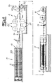
- the plant has in its basic structure a Seilabwickelvorraum 5, a merging device 6, a Vulkanisierpresse 7 and at least one take-up device 8.
- the cable unwinding device 5 has a multiplicity of rotatably mounted cable coils 9, from which the cables 3 to be embedded in the conveyor belt 1 are unwound.
- the steel cables 3 which are under tension and run parallel to one another in a longitudinal direction in the belt, and the steel cable carpet 3 'are combined with the raw rubber tracks 2 to form a raw belt 4.
- the raw belt 4 is vulcanized in the Vulkanisierpresse 7 by means of pressure and heat to form the conveyor belt 1.
- Seilabwickelvortechnische is now formed in the context of the invention as a combined Seilabwickel- and tensioning device 5.
- this cable unwinding and tensioning device 5 each cable 3 is tensioned individually to the required production tension.
- the individual cable coils 9 each with a separate (in the FIGS. 1 to 10 Not shown) equipped clamping drive, which now not only serves to avoid sagging of the rope when unwinding, but with these clamping drives can be adjusted to the required production voltage of the rope tension torque required.
- These tension drives can be designed as electric synchronous motors, which are each equipped or connected to a frequency converter. Details will be later in connection with the Fig. 11 to 13 explained.
- the cable unwinding and tensioning device is equipped with one or more cable tension measuring devices 10 for measuring all individual cable tensions.
- the cable measuring device 10 in each case one or more measuring points 12, wherein each cable 3 (own) measuring point 12 is assigned. Consequently, all tensile stresses can be individually measure and evaluate the individual ropes.
- this measuring device 10 is merely indicated. Structure and operation of this measuring device 10 are based on the Fig. 2 and 3 be explained.
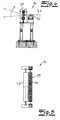
- the cable unwinding and tensioning device 5 has a frame 33 in which the spools 9 are rotatably mounted.
- the individual coils 9 are provided in several floors and, incidentally, a plurality of coils are arranged side by side, are first removed in each case a plurality of individual ropes 3 in a plurality of groups from the Seilabwickelstation.
- Each of these groups can be assigned its own cable measuring device 10.
- Such a cable measuring device 10 is exemplary in the Fig. 2 and 3 shown.
- the cable measuring devices 10 each have a plurality of measuring points 12, which are constructed in the manner of a rope triangle.
- the individual probes 12 have two successively arranged in the transport direction guide rollers 11, between which a plurality of the individual ropes 3 associated probe 12 are arranged as measuring points.
- the geometry of this rope triangle is designed so that the probes 12 dive between the guide rollers 11 by a predetermined amount and thus press on the ropes.
- Each probe 11 is assigned a separate (not shown) load cell, with which the restoring forces generated by the respective cable 3 can be measured.
- the in the Fig. 2 and 3 Guide rollers 11 shown are stationary integrated into the system and thus integrated stationary in the Seilabwickelgestell or connected to this.
- the individual probes 12 are designed as rotatable measuring disks 12, which are suspended with the interposition of the load cells on a common, also stationary support 13. Stationary means here, stationary during the measurement.
- the probe or the carrier adjustable z. B. for adjustment purposes.
- the carrier is then fixed.
- the restoring forces generated in this way are now measured by means of the measuring probes 12 or their measuring boxes.
- the measured values generated in this way are used to control the rope tension, using the already mentioned control device (not shown). This makes it possible to exactly set and regulate all cable tensions in the desired manner, so that conveyor belts can be produced with high quality.
- an alignment device 14 is arranged between the Seilabwickel- and tensioning device 5 and the merging device 6 and Belegevoriques, which a the production distance or in has approximately the production distance of the ropes defining Sp Dretzkamm 15. Structure and operation of such Sp Dretzkamms 15 result from a comparative analysis of Fig. 4, 5 . 6 and 7 ,
- the spreading comb 15 is formed in the embodiment as a rotatably mounted roller comb 15, which has over the outer circumference parallel to each other encircling guide grooves 16 which have a (approximately) the production distance corresponding groove spacing.
- the roller comb 15 is preceded by a guide roller 17, which ensures proper feeding of the starting from different levels of the Seilabwickelstation 5 ropes. especially the Fig. 6 and 7 show that with the help of this Sp Drishmms 15 a narrowing of the rope carpet takes place.
- the roller comb can be composed of a rotatable roller core and a sleeve pushed onto it with the grooves. So can be done by replacing the sleeve adaptation to different cable distances. Details are not shown.
- a conventional solid comb with steel tines can also be used.
- a pulling device 18 which pulls the steel cables 3 and the finished conveyor belt 1 through the entire system before the finished conveyor belt 1 is then wound on the downstream finished belt rewinder 8.
- a separating device 19 may be provided between the pulling device 18 and the finished belt rewinder 8.
- Fig. 1 shown plant works - as already explained - intermittently.
- the vulcanizing press 7 is opened and the finished belt 1 is opened the passage device 18 transported by the length of the last vulcanized.00es.
- the next section of the raw belt to be vulcanized is drawn into the vulcanizing press 7.
- the merging device 6 is designed as a cyclically acting documenting device with a confectioning carriage 36. In the course of Vortransport Schls the finished belt section and not yet assembled steel cables were preferred by the appropriate length. Before this steel cable carpet is now covered with the raw rubber sheets 2 using the packaging trolley 19, the desired production voltage must be applied to the steel cables.
- the desired strip tension is now applied to the individual steel cables 3 and adjusted to the desired target values with the press 7 and "fixed" pulling device 18 by means of the cable unwinding and tensioning station 5 in the described manner.
- the rope carpet is occupied by the confectioning carriage 19 with the raw rubber sheets 2 and partially pre-pressed.
- the Vulkanisierchippresse 7 is closed and there vulcanized the previously transported in Rohgurtabites.
- this documenting device 6 works in cycles, ie the ropes are occupied in the stationary state with the raw rubber by the Rohgurtabwickler back and forth with the carriage 36.
- Fig. 8 shows a modified embodiment in which although the vulcanizing 7 is still designed as a clock press, the Georgia diesel-driven device 6 operates continuously.
- the feeding device 6 has a stationary unwinding device 20 arranged above the steel cables 3 for the upper raw rubber web 2 and a arranged below the steel cables 3, stationary unwinding device 21 for the lower raw rubber web 2 on.
- This unwinding devices 20, 21 is arranged downstream of at least one pressing device 22, with which the steel cables 3 are pressed against each other on or in the raw rubber sheets 2.
- the pressing device 22 is formed as a calender-type roller device with upper roller 23 and lower roller 24. Since the raw rubber webs 2 are usually covered with a release film 25 and wound up, the merging device 6 is equipped in the embodiment with winders 26 for this release film 25. These winders 26 are merely indicated. They are arranged in the transport direction behind the pressing device 22. Incidentally, the system works according to Fig. 8 as the plant according to Fig. 1 , Between Belegevorplatz 6 and press 7, a Beklandmvortechnisch 32 may be arranged.
- the vulcanizing 7 is designed as a continuously operating press. It is in the embodiment to a double belt press with in the press upper part and in the press base endlessly rotating press belts 27, which z. B. are designed as steel belts and are guided over guide rollers 28a, 28b. Furthermore, heatable press plates 29a, 29b are respectively arranged in the press upper part and in the lower press part, wherein the upper press plate 29a and / or the lower press plate 29b is loaded with hydraulic cylinder piston arrangements 30. In the exemplary embodiment is an upper piston press.
- the rotating press belts 27 are with the interposition of WälzSystemaggregaten 31, z. B. rolling rods on the press plates 29 a, 29 b supported.
- Fig. 9 illustrated embodiment is now dispensed with a separate pulling device behind the press.
- the continuous press is thus designed so that with the press belts 27, the steel cables 3 with the required tensile force through the plant can be pulled through.
- the cable unwinding and tensioning device 5 thus sets the desired tensile forces of the individual cables 3 against the pulling continuous press 7.
- the cable unwinding station 5 has a cable unwinding rack 33 and a plurality of cable unwinding units 40 arranged on the cable unwinding rack 33.
- Each cable unwinding unit 40 is composed essentially of a drive unit 41, 42 and a cable reel 9, wherein the cables 3 to be embedded in the conveyor belt 1 are unwound from the individual cable reels 9 of the cable unwinding units 40.
- the cable coils 9 are detachable and consequently interchangeable with the drive units 41, 42 connected.
- the drive unit 41, 42 has at least one motor 41 and at least one transmission 42.
- the transmission is equipped with an output shaft 47.
- the drive unit 41, 42 the cable spool 9 is driven.
- the ropes are withdrawn or unwound, for example, by the cable device 9 integrated into the system by the cable coils 9, so that the drive unit 41, 42 is formed in the context of the invention as a brake and / or tensioning unit, which the to be unwound ropes 3 under a predetermined tension.
- the generation of the required is done via the brake and / or clamping units Production tension of the ropes.
- the clamping motors 41 are z. B. formed as an electric synchronous motors, which may each be equipped or connected to a frequency converter.
- the cable reel 9 of a cable unwinding device 40 is now - as in Fig. 11 to 13 shown - attached directly to the integrated into the transmission 42 and projecting from the transmission output shaft 47.
- Fig. 11 shows an example along the working direction extending longitudinal member 33 'of Seilabwickelgestells 33.
- the drive unit 41, 42 is placed, which is composed essentially of motor 41 and gear 42, the motor 41 itself in the Fig. 11 or 12 is not shown in detail.
- the output shaft 47 integrated into the transmission 42 now protrudes from the transmission 42 by a predetermined length L, this length L being greater than the width B of the cable coil. This allows the cable reel 9 can be plugged directly onto the output shaft 47 projecting from the transmission, without a separate spool shaft would have to be rotatably connected to a normalized output shaft of the transmission.
- the output shaft 47 is formed as a non-profiled smooth shaft made of high-strength steel with a smooth surface. This has a round cross section. It engages in a SpulenausEnglishung with also round cross-section.
- a driver 48 is provided, which on the one hand rotatably secured to the output shaft 47 and on the other hand, a non-rotatable - but releasable - connection with the cable coil 9 allows.
- the driver 48 is positively connected to the output shaft 47, z. B. via a clamping element 49.
- This clamping element 49 is in Fig. 11 only simplified. It may, for example, be a ring tensioning element 49.
- the driver 48 in the embodiment, a plurality of eccentrically arranged pin 50, which engage in likewise eccentrically arranged, corresponding recesses 51 of the cable reel. In this way, high tensile forces or torques can be transmitted. Nevertheless, a simple interchangeability of the cable coil 9 is guaranteed.
- the frictional clamping connection between the driver 48 and the output shaft 47 welds are avoided, which could affect the strength of the output shaft 47.
- the positive connection between the cable reel 9 and driver 48 allows easy replacement of the cable reel.
- the cable coil 9 in the axial direction with a fuse element 52, z. B. a locking washer is secured.
- the pin 50 and / or the recess 51 may be conical and have a widening with increasing depth cross-section. Such a configuration is not shown in the figures. It makes it possible, if necessary, to dispense with the securing element. Because of the conical configuration of pin and / or recess, the tensile forces are deflected during operation so that the cable coil is pulled as it were by itself to the driver.
- the cable unwinding unit 45 is characterized by a simple and very compact construction, since it is no longer necessary to connect a standardized output shaft of a standard gearbox to a conventional spool shaft.
- the output shaft 47 is formed as a profiled shaft having a deviating from the circular cross-section, namely a polygonal cross-section.
- the output shaft 47 has a quadrangular cross section, z. B. square cross section.
- This profiled output shaft 47 engages in a corresponding Spulenaus aloneung the cable reel 9, ie, this SpulenausNFung also has a deviating from the circular cross-section, z. B. polygonal cross section.
- this cross-section is quadrangular in the embodiment, namely formed square.
- the output shaft 47 engages torque-transmitting rotatably and positively in the Spulenaus originallyung.
- a driver such as in Fig. 11 is shown to dispense, since the torque transmission can be realized directly via the output shaft 47.
- the cable coil 9 in the axial direction with a fuse element 52, z. B. secure with a lock washer.
Landscapes
- Engineering & Computer Science (AREA)
- Mechanical Engineering (AREA)
- Tension Adjustment In Filamentary Materials (AREA)
- Ropes Or Cables (AREA)
- Belt Conveyors (AREA)
- Forwarding And Storing Of Filamentary Material (AREA)
- Structure Of Belt Conveyors (AREA)
- Tyre Moulding (AREA)
- Bridges Or Land Bridges (AREA)
- Devices For Conveying Motion By Means Of Endless Flexible Members (AREA)
Claims (21)
- Installation de fabrication de courroies de transport (1) avec câbles intégrés, par ex. câbles d'acier intégrés, comprenant au moins- un dispositif de déroulement de câble (5) comprenant plusieurs bobines de câble (9) desquelles les câbles à enchâsser dans la courroie de transport (1), par ex. des câbles d'acier (3), sont déroulés,- un dispositif de regroupement (6) dans lequel les câbles (3) en effort de traction et parallèles les uns aux autres dans un plan dans le sens longitudinal de la courroie, sont regroupés en une courroie brute (4) avec un ou plusieurs lés de caoutchouc brut (2),- une presse à vulcanisation (7) dans laquelle la courroie brute (4) est vulcanisée au moyen de pression et/ou de chaleur pour former la courroie de transport (1),caractérisée en ce que le dispositif de déroulement de câble est conçu en tant que dispositif de déroulement et de tension de câble (5), dans lequel chaque câble (3) est tendu individuellement à la tension de production requise,
sachant que les bobines de câble (9) individuelles sont dotées de, respectivement reliées à, au moins un entraînement de tension ou un groupe d'entraînement de tension à moteur électrique, avec lequel le couple de tension requis peut être réglé pour produire la tension de production requise du câble (3),
sachant que le dispositif de déroulement et de tension de câble (5) est doté d'un ou plusieurs dispositif(s) de mesure de traction de câble (10) avec lequel/lesquels l'effort de traction des différents câbles (3) peut être mesuré, sachant que chaque câble (3) a un point de mesure (12),
sachant que le dispositif de déroulement et de tension de câble (5) est doté d'un dispositif de commande et/ou de réglage qui est relié d'une part au dispositif de mesure de traction de câble (10), respectivement aux points de mesure (12), et d'autre part aux entraînements de tension. - Installation selon la revendication 1, caractérisée en ce que les entraînements de tension sont conçus en tant que moteurs synchrones électriques ou sont dotés de moteurs synchrones électriques, qui sont dotés ou reliés, ensemble ou chacun, au moins à un convertisseur de fréquences.
- Installation selon la revendication 1 ou 2, comprenant un bâti de déroulement de câble (33) dans lequel les bobines de câble (9) peuvent tourner et sont disposées en étant entraînées par les entraînements de tension, respectivement les groupes d'entraînement de tension, caractérisée en ce que le dispositif de mesure de traction de câble (10) est intégré dans le bâti de déroulement de câble (33), est disposé par ex. sur l'extrémité côté sortie du bâti de déroulement de câble (33).
- Installation selon l'une des revendications 1 à 3, caractérisée en ce que les points de mesure (12) sont formés par des palpeurs de mesure (12) correspondant aux différents câbles.
- Installation selon la revendication 4, caractérisée en ce que les palpeurs de mesure sont conçus en tant que disques de mesure (12) ou cylindres de mesure qui sont reliés à ou sont dotés de cellules de mesure de la force.
- Installation selon la revendication 4 ou 5, caractérisée en ce que le dispositif de mesure de traction de câble (10) présente au moins deux cylindres de guidage (11) disposés l'un derrière l'autre dans le sens de transport à la manière d'un triangle de câbles, entre lesquels le palpeur de mesure (12) plonge avec une dimension prédéfinie en appuyant sur les câbles, sachant que la force de rappel produite par le câble respectif peut être mesurée avec les palpeurs de mesure (12).
- Installation selon l'une des revendications 1 à 6, comprenant un dispositif de passe (18) en aval de la presse à vulcanisation (7), caractérisée en ce que les câbles (3) peuvent être tendus à la tension de production avec le dispositif de déroulement et de tension de câble (5), entre le dispositif de déroulement et de tension de câble (5) et le dispositif de passe (18).
- Installation selon l'une des revendications 1 à 7, caractérisée en ce qu'au moins un dispositif d'alignement (14) avec au moins un peigne écarteur (15) modifiant l'écart entre les câbles, est disposé entre le dispositif de déroulement et de tension de câble (5) et le dispositif de regroupement (6), dans lequel les différents câbles (3) sont déviés à différents angles dans le plan de la courroie.
- Installation selon l'une des revendications 1 à 8, caractérisée en ce qu'un groupe d'entraînement (41, 42) présente au moins un moteur (41) et au moins un engrenage (42) avec un arbre de sortie (47), sachant que la bobine de câble (9) est enchâssée directement sur l'arbre de sortie (47) intégré dans l'engrenage (42) et dépassant de l'engrenage (42).
- Installation selon la revendication 9, caractérisée en ce que l'arbre de sortie (47) intégré dans l'engrenage (42) dépasse de l'engrenage (42) d'une longueur prédéfinie (L) qui correspond au moins à la largeur (B) de la bobine de câble (9) ou est plus grande que celle-ci.
- Installation selon la revendication 9 ou 10, caractérisée en ce que l'arbre de sortie (47) est conçu en tant qu'arbre profilé avec une section s'écartant de la forme circulaire, par exemple une section pluri-angulaire, et se met en prise de façon fixe et par complémentarité de forme dans un évidement correspondant de la bobine de câble (9) pour transmettre le couple de rotation.
- Installation selon la revendication 9 ou 10, caractérisée en ce que l'arbre de sortie (47) est conçu en tant qu'arbre lisse non profilé de section ronde, par ex. en acier haute résistance avec une surface lisse.
- Installation selon l'une des revendications 9 à 12, caractérisée en ce que la bobine de câble (9) est fixée ou peut être fixée à l'arbre de sortie (47) par le biais d'un entraîneur (48), en étant fixe en rotation.
- Installation selon la revendication 13, caractérisé en ce que l'entraîneur (48) est fixé par adhérence de force à l'arbre de sortie (47), au moyen d'un élément de serrage (49), par exemple un élément de serrage à collier.
- Installation selon la revendication 12 ou 14, caractérisée en ce que la bobine de câble (9) est fixée par adhérence de formes ou de façon amovible à l'entraîneur (48).
- Installation selon la revendication 15, caractérisée en ce que l'entraîneur (48) présente une ou plusieurs broches (50) disposées de façon excentrique, réparties par exemple de façon excentrique autour de l'arbre, lesquelles s'étendent par exemple dans le sens axial et s'engagent dans des évidements (51) de la bobine de câble (9) disposés de façon excentrique.
- Installation selon la revendication 16, caractérisée en ce que les broches (50) et/ou l'évidement (51) est/sont conçu(e)s conique(s) et présente(nt) une section transversale s'élargissant avec une profondeur croissante.
- Installation selon l'une des revendications 9 à 17, caractérisée en ce que le moteur (41) est conçu en tant que moteur électrique, par exemple un moteur synchrone électrique.
- Installation selon l'une des revendications 9 à 18, caractérisée en ce que l'engrenage (42) est conçu en tant que démultiplicateur, par exemple en tant qu'engrenage à roues coniques.
- Procédé de fabrication de courroies de transport comprenant des câbles d'acier insérés avec une installation selon l'une des revendications 1 à 19, caractérisé en ce que les tensions des différents câbles sont mesurées et réglées à une ou des valeur(s) de consigne souhaitée(s)en tenant compte des résultats de mesure dans le dispositif de déroulement et de tension de câble.
- Procédé selon la revendication 20, dans lequel les câbles sont déviés différemment dans un peigne d'écartement disposé entre le dispositif de déroulement de câbles et le dispositif d'amenée, par modification de la tension des différents câbles dans le plan de la courroie, caractérisé en ce que la tension de câble dans le dispositif de déroulement et de tension de câble est réglée ou régulée avec la mesure, que les tensions de production souhaitées sont données après le peigne de guidage en tenant compte des modifications de tension de câble dans le peigne de guidage.
Applications Claiming Priority (3)
| Application Number | Priority Date | Filing Date | Title |
|---|---|---|---|
| DE201010008531 DE102010008531A1 (de) | 2010-02-18 | 2010-02-18 | Anlage und Verfahren zum Herstellen von Fördergurten mit Stahlseileinlage |
| DE102010037986.7A DE102010037986B4 (de) | 2010-10-05 | 2010-10-05 | Seilabwickeleinheit |
| PCT/EP2011/052357 WO2011101410A1 (fr) | 2010-02-18 | 2011-02-17 | Installation et dispositif de fabrication de courroies transporteuses à nappe de câbles en acier |
Publications (2)
| Publication Number | Publication Date |
|---|---|
| EP2536554A1 EP2536554A1 (fr) | 2012-12-26 |
| EP2536554B1 true EP2536554B1 (fr) | 2016-05-04 |
Family
ID=44070668
Family Applications (1)
| Application Number | Title | Priority Date | Filing Date |
|---|---|---|---|
| EP11704224.2A Active EP2536554B1 (fr) | 2010-02-18 | 2011-02-17 | Systeme et procede de fabrication des bandes transporteuses avec armure en acier |
Country Status (13)
| Country | Link |
|---|---|
| US (1) | US9278493B2 (fr) |
| EP (1) | EP2536554B1 (fr) |
| JP (1) | JP5749745B2 (fr) |
| CN (1) | CN102770264B (fr) |
| AU (1) | AU2011217287B2 (fr) |
| BR (1) | BR112012020707B1 (fr) |
| CA (1) | CA2790640C (fr) |
| CL (1) | CL2012002284A1 (fr) |
| ES (1) | ES2586134T3 (fr) |
| HU (1) | HUE030125T2 (fr) |
| PL (1) | PL2536554T3 (fr) |
| RU (1) | RU2543175C2 (fr) |
| WO (1) | WO2011101410A1 (fr) |
Families Citing this family (18)
| Publication number | Priority date | Publication date | Assignee | Title |
|---|---|---|---|---|
| CN102642691A (zh) * | 2012-05-03 | 2012-08-22 | 白景魁 | 多层织物橡胶输送带无缝连接的方法 |
| FR3001032B1 (fr) * | 2013-01-17 | 2015-03-13 | Snecma | Dispositif de mesure de profil interne d'un arbre creux |
| JP6547236B2 (ja) * | 2015-02-03 | 2019-07-24 | 住友ゴム工業株式会社 | コード−ゴムコーティング反の製造方法および製造装置 |
| DE102015223796A1 (de) * | 2015-11-30 | 2017-06-01 | Contitech Transportbandsysteme Gmbh | Verfahren zur Herstellung eines Transportbandes |
| DE102016106079B4 (de) * | 2016-04-04 | 2020-06-04 | Hans Schmidt & Co GmbH | Mobile Zugspannungsmessvorrichtung |
| DE102016106076B4 (de) * | 2016-04-04 | 2020-06-10 | Hans Schmidt & Co GmbH | Mobile Zugspannungsmessvorrichtung |
| CN106273338B (zh) * | 2016-10-31 | 2019-03-19 | 珠海汉胜科技股份有限公司 | 一种套管的生产方法和紧压式牵引装置 |
| US10969556B1 (en) * | 2017-04-24 | 2021-04-06 | NET Recycling, LLC | Method and apparatus for removing optic fiber from multiple spools |
| CN107253594B (zh) * | 2017-06-13 | 2023-03-14 | 青岛祥杰橡胶机械制造有限公司 | 一种输送带的生产设备及其生产工艺 |
| CN107225747A (zh) * | 2017-07-10 | 2017-10-03 | 阳春市恒耐工业皮带有限公司 | 一种聚氨酯同步带挤出成型设备 |
| US10246291B2 (en) * | 2017-07-31 | 2019-04-02 | Sunshine Kinetics Technology Co. Ltd. | Yarn feeder |
| CN107877872B (zh) * | 2017-11-22 | 2020-03-27 | 徐州华显凯星信息科技有限公司 | 一种施工封堵用密封胶垫芯材嵌入装置及其方法 |
| CN110744842B (zh) * | 2019-10-15 | 2021-08-31 | 浙江天梯塑胶科技有限公司 | 一种可伸缩编织管的生产设备 |
| US12385168B2 (en) * | 2019-10-17 | 2025-08-12 | Rjs Corporation | Digital creel system |
| CN110948912B (zh) * | 2019-12-12 | 2021-09-28 | 国塑机械(上海)有限公司 | 一种热塑性连续碳纤维单向带的生产设备及生产工艺 |
| EP3859925B1 (fr) * | 2020-01-28 | 2023-09-06 | Sandvik Mining and Construction Oy | Agencement, véhicule et procédé |
| CN112373082A (zh) * | 2020-10-15 | 2021-02-19 | 沈阳城市公用集团橡胶制品有限公司 | 一种阻燃输送带生产系统及方法 |
| CN113681872B (zh) * | 2021-09-27 | 2025-08-22 | 黄石宏和电子材料科技有限公司 | 一种防止产生拉丝中心偏移装置及其使用方法 |
Citations (4)
| Publication number | Priority date | Publication date | Assignee | Title |
|---|---|---|---|---|
| US2102680A (en) * | 1934-09-28 | 1937-12-21 | George B Cocker | Creel |
| DE1921969A1 (de) * | 1969-04-30 | 1971-06-16 | Siempelkamp Gmbh & Co | Anlage zur Herstellung von Foerderbaendern |
| DE2254027A1 (de) * | 1972-11-04 | 1974-05-16 | Continental Gummi Werke Ag | Verfahren und vorrichtung zum herstellen von foerdergurten |
| DE2258413A1 (de) * | 1972-11-29 | 1974-06-12 | Mitsuboshi Belting Ltd | Vorrichtung und verfahren zum herstellen eines foerderbandes |
Family Cites Families (21)
| Publication number | Priority date | Publication date | Assignee | Title |
|---|---|---|---|---|
| US2740459A (en) * | 1951-06-23 | 1956-04-03 | Goodyear Tire & Rubber | Method and apparatus for building wire reinforced conveyor belts |
| GB1013639A (en) * | 1963-05-28 | 1965-12-15 | Continental Gummi Werke Ag | Method and apparatus for stretching wires or cables |
| US3345229A (en) * | 1963-12-04 | 1967-10-03 | Goodyear Tire & Rubber | Belt manufacturing apparatus |
| DE1282912B (de) * | 1966-04-30 | 1968-11-14 | Siempelkamp Gmbh & Co | Vorrichtung zum Spannen der laengslaufenden Seile, insbesondere Stahl- oder Kunststoffseile, von Verstaerkungseinlagen fuer Foerderbaender |
| NL6910454A (fr) * | 1968-08-02 | 1970-02-04 | ||
| DE2104501C3 (de) * | 1971-02-01 | 1979-07-26 | Clouth Gummiwerke Ag, 5000 Koeln | Einrichtung zur Herstellung von Fördergurten mit Stahlseileinlagen |
| US3687394A (en) | 1971-06-09 | 1972-08-29 | Goodyear Tire & Rubber | Cord creel |
| US3941637A (en) * | 1972-11-09 | 1976-03-02 | Mitsubishi Belting Limited | Method of manufacturing a conveyor belt and an apparatus therefor |
| IT1114656B (it) * | 1977-09-30 | 1986-01-27 | Pirelli | Impianto per la vulcanizzazione di elementi nastriformi |
| DE2845476A1 (de) * | 1978-10-19 | 1980-04-24 | Berstorff Gmbh Masch Hermann | Verfahren und vorrichtung zum kontinuierlichen herstellen eines foerdergurtes |
| US4257833A (en) * | 1979-11-19 | 1981-03-24 | The Goodyear Tire & Rubber Company | Method of manufacture of cable belts having generally symmetrically tensioned cables |
| DE3037611C1 (de) | 1980-10-04 | 1982-04-01 | G. Siempelkamp Gmbh & Co, 4150 Krefeld | Anlage zum Herstellen von Foerdergurten mit Stahlseileinlagen |
| JPH05229028A (ja) * | 1992-02-24 | 1993-09-07 | Bando Chem Ind Ltd | ゴムベルト成形機へのコード繰出装置 |
| CN2242174Y (zh) * | 1995-12-30 | 1996-12-11 | 阜新橡胶总厂 | 输送带成型机 |
| CA2315658A1 (fr) * | 1998-02-03 | 1999-08-12 | David Paul Schweitzer | Procede de fabrication de bande transporteuse renforcee par des cables en acier |
| DE19828736C2 (de) | 1998-06-27 | 2003-04-24 | Siempelkamp Gmbh & Co Kg G | Vorrichtung zum Spannen von in Förderbänder, insbesondere Gummibänder, einzubettenden Verstärkungsseilen |
| WO2002086348A1 (fr) | 2001-04-18 | 2002-10-31 | The Coe Manufacturing Company | Appareil et procede de fabrication de courroies |
| CN100467259C (zh) * | 2006-12-12 | 2009-03-11 | 浙江紫金港胶带有限公司 | 胶套密封式齿形切边v带反成型硫化方法 |
| MX2009011342A (es) * | 2007-04-20 | 2009-11-05 | Invista Tech Sarl | Fileta compacta de desenrollamiento continuo por encima con control de tension. |
| PL2201266T3 (pl) * | 2007-09-14 | 2019-03-29 | Gates Corporation | Żebrowany pas klinowy i sposób jego wytwarzania |
| DE102008042201B4 (de) * | 2007-09-27 | 2023-12-21 | Baumüller Nürnberg GmbH | Elektromotorischer Verspannmechanismus und Startmethodik dafür |
-
2011
- 2011-02-17 RU RU2012139827/05A patent/RU2543175C2/ru active
- 2011-02-17 CA CA2790640A patent/CA2790640C/fr active Active
- 2011-02-17 PL PL11704224T patent/PL2536554T3/pl unknown
- 2011-02-17 WO PCT/EP2011/052357 patent/WO2011101410A1/fr not_active Ceased
- 2011-02-17 JP JP2012553319A patent/JP5749745B2/ja active Active
- 2011-02-17 AU AU2011217287A patent/AU2011217287B2/en active Active
- 2011-02-17 EP EP11704224.2A patent/EP2536554B1/fr active Active
- 2011-02-17 BR BR112012020707-5A patent/BR112012020707B1/pt active IP Right Grant
- 2011-02-17 US US13/521,675 patent/US9278493B2/en active Active
- 2011-02-17 CN CN201180009909.8A patent/CN102770264B/zh active Active
- 2011-02-17 ES ES11704224.2T patent/ES2586134T3/es active Active
- 2011-02-17 HU HUE11704224A patent/HUE030125T2/en unknown
-
2012
- 2012-08-17 CL CL2012002284A patent/CL2012002284A1/es unknown
Patent Citations (4)
| Publication number | Priority date | Publication date | Assignee | Title |
|---|---|---|---|---|
| US2102680A (en) * | 1934-09-28 | 1937-12-21 | George B Cocker | Creel |
| DE1921969A1 (de) * | 1969-04-30 | 1971-06-16 | Siempelkamp Gmbh & Co | Anlage zur Herstellung von Foerderbaendern |
| DE2254027A1 (de) * | 1972-11-04 | 1974-05-16 | Continental Gummi Werke Ag | Verfahren und vorrichtung zum herstellen von foerdergurten |
| DE2258413A1 (de) * | 1972-11-29 | 1974-06-12 | Mitsuboshi Belting Ltd | Vorrichtung und verfahren zum herstellen eines foerderbandes |
Also Published As
| Publication number | Publication date |
|---|---|
| WO2011101410A1 (fr) | 2011-08-25 |
| CN102770264B (zh) | 2015-06-24 |
| JP5749745B2 (ja) | 2015-07-15 |
| JP2013519548A (ja) | 2013-05-30 |
| CA2790640A1 (fr) | 2011-08-25 |
| CL2012002284A1 (es) | 2013-03-08 |
| HUE030125T2 (en) | 2017-04-28 |
| PL2536554T3 (pl) | 2017-01-31 |
| RU2012139827A (ru) | 2014-03-27 |
| ES2586134T3 (es) | 2016-10-11 |
| AU2011217287B2 (en) | 2014-08-14 |
| CA2790640C (fr) | 2014-10-28 |
| BR112012020707A2 (pt) | 2016-07-26 |
| CN102770264A (zh) | 2012-11-07 |
| US9278493B2 (en) | 2016-03-08 |
| US20130098525A1 (en) | 2013-04-25 |
| RU2543175C2 (ru) | 2015-02-27 |
| EP2536554A1 (fr) | 2012-12-26 |
| AU2011217287A1 (en) | 2012-08-30 |
| BR112012020707B1 (pt) | 2020-05-26 |
Similar Documents
| Publication | Publication Date | Title |
|---|---|---|
| EP2536554B1 (fr) | Systeme et procede de fabrication des bandes transporteuses avec armure en acier | |
| EP2138615B1 (fr) | Procédé de fabrication d'une nappe multiaxiale, couches de fibres unidirectionnelles et leur procédé de fabrication, nappe multiaxiale et pièce composite dotée d'une matrice | |
| EP2327648B1 (fr) | Dispositif et procédé de production d'une couche UD | |
| DE4407964A1 (de) | Verfahren und Vorrichtung zum automatischen Auflegen und Spleißen von Materialbahnen auf eine Reifenaufbautrommel | |
| EP2151517B1 (fr) | Procédé de fabrication d'une couche de fibre unidirectionnelle et dispositif d'écartement de fibres | |
| DE102008057463C5 (de) | Verfahren und Vorrichtung zur Herstellung einer Feder aus einem Faserverbundwerkstoff | |
| WO2018138000A1 (fr) | Treuil à câble passant | |
| EP1000892B1 (fr) | Méthode pour le fonctionnement d'un dispositif d'enroulement et dispositif d'enroulement | |
| CH668588A5 (de) | Verfahren und vorrichtung zum lagerichtigen einspannen eines wickeltragbaumes. | |
| DE102010008530B4 (de) | Anlage zum Herstellen von Fördergurten mit Stahlseileinlage | |
| DE102010008529B4 (de) | Anlage und Verfahren zum Herstellen von Fördergurten mit Stahlseileinlage | |
| DE102005050008B4 (de) | Vorrichtung und Verfahren zum Wickeln von endlosen Schraubenfedern | |
| EP2336407B1 (fr) | Dispositif de montage pour garnitures de carde en acier | |
| WO2015172932A1 (fr) | Dispositif et procédé de détermination de propriétés matérielles d'une feuille continue de matériau d'emballage, de préférence dans une machine d'emballage, ainsi que machine d'emballage | |
| DE102010008531A1 (de) | Anlage und Verfahren zum Herstellen von Fördergurten mit Stahlseileinlage | |
| WO2011101421A1 (fr) | Dispositif de fabrication de bandes transporteuses comportant des inserts en câble d'acier | |
| DE1964320A1 (de) | Kabel mit nichtmetallischer Seele | |
| DE102015000545B4 (de) | Anlage zum Herstellen von Fördergurten | |
| DE102008057462A1 (de) | Feder aus einem Faserverbundwerkstoff sowie Verfahren und Vorrichtung zur Herstellung derselben | |
| DE102012020135A1 (de) | Verfahren und Wickelvorrichtung zur Herstellung eines Fadenpakets | |
| DE10011132C2 (de) | Legeanordnung für mehrschichtige Multiaxialfadengelege | |
| DE102021101531B4 (de) | Haspel zum Aufwickeln oder Abwickeln von bandförmigen Material und Verfahren | |
| EP4281231B1 (fr) | Bobineuse pour enrouler ou dérouler un matériau en forme de bande et procédé | |
| DE102010037986B4 (de) | Seilabwickeleinheit | |
| EP3630467B1 (fr) | Procédé et dispositif de fabrication d'un profilé en matière synthétique |
Legal Events
| Date | Code | Title | Description |
|---|---|---|---|
| PUAI | Public reference made under article 153(3) epc to a published international application that has entered the european phase |
Free format text: ORIGINAL CODE: 0009012 |
|
| 17P | Request for examination filed |
Effective date: 20120718 |
|
| AK | Designated contracting states |
Kind code of ref document: A1 Designated state(s): AL AT BE BG CH CY CZ DE DK EE ES FI FR GB GR HR HU IE IS IT LI LT LU LV MC MK MT NL NO PL PT RO RS SE SI SK SM TR |
|
| DAX | Request for extension of the european patent (deleted) | ||
| 17Q | First examination report despatched |
Effective date: 20140122 |
|
| RAP1 | Party data changed (applicant data changed or rights of an application transferred) |
Owner name: SIEMPELKAMP MASCHINEN- UND ANLAGENBAU GMBH |
|
| GRAP | Despatch of communication of intention to grant a patent |
Free format text: ORIGINAL CODE: EPIDOSNIGR1 |
|
| INTG | Intention to grant announced |
Effective date: 20151204 |
|
| INTC | Intention to grant announced (deleted) | ||
| INTG | Intention to grant announced |
Effective date: 20151216 |
|
| GRAS | Grant fee paid |
Free format text: ORIGINAL CODE: EPIDOSNIGR3 |
|
| GRAA | (expected) grant |
Free format text: ORIGINAL CODE: 0009210 |
|
| AK | Designated contracting states |
Kind code of ref document: B1 Designated state(s): AL AT BE BG CH CY CZ DE DK EE ES FI FR GB GR HR HU IE IS IT LI LT LU LV MC MK MT NL NO PL PT RO RS SE SI SK SM TR |
|
| REG | Reference to a national code |
Ref country code: GB Ref legal event code: FG4D Free format text: NOT ENGLISH |
|
| REG | Reference to a national code |
Ref country code: CH Ref legal event code: EP |
|
| REG | Reference to a national code |
Ref country code: AT Ref legal event code: REF Ref document number: 796522 Country of ref document: AT Kind code of ref document: T Effective date: 20160515 |
|
| REG | Reference to a national code |
Ref country code: IE Ref legal event code: FG4D Free format text: LANGUAGE OF EP DOCUMENT: GERMAN |
|
| REG | Reference to a national code |
Ref country code: DE Ref legal event code: R096 Ref document number: 502011009643 Country of ref document: DE |
|
| REG | Reference to a national code |
Ref country code: NL Ref legal event code: FP |
|
| REG | Reference to a national code |
Ref country code: LT Ref legal event code: MG4D |
|
| REG | Reference to a national code |
Ref country code: ES Ref legal event code: FG2A Ref document number: 2586134 Country of ref document: ES Kind code of ref document: T3 Effective date: 20161011 |
|
| PG25 | Lapsed in a contracting state [announced via postgrant information from national office to epo] |
Ref country code: LT Free format text: LAPSE BECAUSE OF FAILURE TO SUBMIT A TRANSLATION OF THE DESCRIPTION OR TO PAY THE FEE WITHIN THE PRESCRIBED TIME-LIMIT Effective date: 20160504 Ref country code: NO Free format text: LAPSE BECAUSE OF FAILURE TO SUBMIT A TRANSLATION OF THE DESCRIPTION OR TO PAY THE FEE WITHIN THE PRESCRIBED TIME-LIMIT Effective date: 20160804 Ref country code: FI Free format text: LAPSE BECAUSE OF FAILURE TO SUBMIT A TRANSLATION OF THE DESCRIPTION OR TO PAY THE FEE WITHIN THE PRESCRIBED TIME-LIMIT Effective date: 20160504 |
|
| PG25 | Lapsed in a contracting state [announced via postgrant information from national office to epo] |
Ref country code: SE Free format text: LAPSE BECAUSE OF FAILURE TO SUBMIT A TRANSLATION OF THE DESCRIPTION OR TO PAY THE FEE WITHIN THE PRESCRIBED TIME-LIMIT Effective date: 20160504 Ref country code: LV Free format text: LAPSE BECAUSE OF FAILURE TO SUBMIT A TRANSLATION OF THE DESCRIPTION OR TO PAY THE FEE WITHIN THE PRESCRIBED TIME-LIMIT Effective date: 20160504 Ref country code: HR Free format text: LAPSE BECAUSE OF FAILURE TO SUBMIT A TRANSLATION OF THE DESCRIPTION OR TO PAY THE FEE WITHIN THE PRESCRIBED TIME-LIMIT Effective date: 20160504 Ref country code: RS Free format text: LAPSE BECAUSE OF FAILURE TO SUBMIT A TRANSLATION OF THE DESCRIPTION OR TO PAY THE FEE WITHIN THE PRESCRIBED TIME-LIMIT Effective date: 20160504 Ref country code: PT Free format text: LAPSE BECAUSE OF FAILURE TO SUBMIT A TRANSLATION OF THE DESCRIPTION OR TO PAY THE FEE WITHIN THE PRESCRIBED TIME-LIMIT Effective date: 20160905 |
|
| PG25 | Lapsed in a contracting state [announced via postgrant information from national office to epo] |
Ref country code: IT Free format text: LAPSE BECAUSE OF FAILURE TO SUBMIT A TRANSLATION OF THE DESCRIPTION OR TO PAY THE FEE WITHIN THE PRESCRIBED TIME-LIMIT Effective date: 20160504 |
|
| PG25 | Lapsed in a contracting state [announced via postgrant information from national office to epo] |
Ref country code: EE Free format text: LAPSE BECAUSE OF FAILURE TO SUBMIT A TRANSLATION OF THE DESCRIPTION OR TO PAY THE FEE WITHIN THE PRESCRIBED TIME-LIMIT Effective date: 20160504 Ref country code: DK Free format text: LAPSE BECAUSE OF FAILURE TO SUBMIT A TRANSLATION OF THE DESCRIPTION OR TO PAY THE FEE WITHIN THE PRESCRIBED TIME-LIMIT Effective date: 20160504 Ref country code: RO Free format text: LAPSE BECAUSE OF FAILURE TO SUBMIT A TRANSLATION OF THE DESCRIPTION OR TO PAY THE FEE WITHIN THE PRESCRIBED TIME-LIMIT Effective date: 20160504 Ref country code: SK Free format text: LAPSE BECAUSE OF FAILURE TO SUBMIT A TRANSLATION OF THE DESCRIPTION OR TO PAY THE FEE WITHIN THE PRESCRIBED TIME-LIMIT Effective date: 20160504 |
|
| REG | Reference to a national code |
Ref country code: GR Ref legal event code: EP Ref document number: 20160401820 Country of ref document: GR Effective date: 20161118 |
|
| REG | Reference to a national code |
Ref country code: DE Ref legal event code: R097 Ref document number: 502011009643 Country of ref document: DE |
|
| REG | Reference to a national code |
Ref country code: FR Ref legal event code: PLFP Year of fee payment: 7 |
|
| PG25 | Lapsed in a contracting state [announced via postgrant information from national office to epo] |
Ref country code: SM Free format text: LAPSE BECAUSE OF FAILURE TO SUBMIT A TRANSLATION OF THE DESCRIPTION OR TO PAY THE FEE WITHIN THE PRESCRIBED TIME-LIMIT Effective date: 20160504 |
|
| PLBE | No opposition filed within time limit |
Free format text: ORIGINAL CODE: 0009261 |
|
| STAA | Information on the status of an ep patent application or granted ep patent |
Free format text: STATUS: NO OPPOSITION FILED WITHIN TIME LIMIT |
|
| 26N | No opposition filed |
Effective date: 20170207 |
|
| REG | Reference to a national code |
Ref country code: HU Ref legal event code: AG4A Ref document number: E030125 Country of ref document: HU |
|
| PG25 | Lapsed in a contracting state [announced via postgrant information from national office to epo] |
Ref country code: SI Free format text: LAPSE BECAUSE OF FAILURE TO SUBMIT A TRANSLATION OF THE DESCRIPTION OR TO PAY THE FEE WITHIN THE PRESCRIBED TIME-LIMIT Effective date: 20160504 Ref country code: BE Free format text: LAPSE BECAUSE OF NON-PAYMENT OF DUE FEES Effective date: 20170228 |
|
| PG25 | Lapsed in a contracting state [announced via postgrant information from national office to epo] |
Ref country code: MC Free format text: LAPSE BECAUSE OF FAILURE TO SUBMIT A TRANSLATION OF THE DESCRIPTION OR TO PAY THE FEE WITHIN THE PRESCRIBED TIME-LIMIT Effective date: 20160504 |
|
| REG | Reference to a national code |
Ref country code: CH Ref legal event code: PL |
|
| PG25 | Lapsed in a contracting state [announced via postgrant information from national office to epo] |
Ref country code: LI Free format text: LAPSE BECAUSE OF NON-PAYMENT OF DUE FEES Effective date: 20170228 Ref country code: CH Free format text: LAPSE BECAUSE OF NON-PAYMENT OF DUE FEES Effective date: 20170228 |
|
| REG | Reference to a national code |
Ref country code: IE Ref legal event code: MM4A |
|
| PG25 | Lapsed in a contracting state [announced via postgrant information from national office to epo] |
Ref country code: LU Free format text: LAPSE BECAUSE OF NON-PAYMENT OF DUE FEES Effective date: 20170217 |
|
| REG | Reference to a national code |
Ref country code: BE Ref legal event code: MM Effective date: 20170228 |
|
| REG | Reference to a national code |
Ref country code: FR Ref legal event code: PLFP Year of fee payment: 8 |
|
| PG25 | Lapsed in a contracting state [announced via postgrant information from national office to epo] |
Ref country code: IE Free format text: LAPSE BECAUSE OF NON-PAYMENT OF DUE FEES Effective date: 20170217 |
|
| PG25 | Lapsed in a contracting state [announced via postgrant information from national office to epo] |
Ref country code: MT Free format text: LAPSE BECAUSE OF FAILURE TO SUBMIT A TRANSLATION OF THE DESCRIPTION OR TO PAY THE FEE WITHIN THE PRESCRIBED TIME-LIMIT Effective date: 20160504 |
|
| PG25 | Lapsed in a contracting state [announced via postgrant information from national office to epo] |
Ref country code: AL Free format text: LAPSE BECAUSE OF FAILURE TO SUBMIT A TRANSLATION OF THE DESCRIPTION OR TO PAY THE FEE WITHIN THE PRESCRIBED TIME-LIMIT Effective date: 20160504 |
|
| PG25 | Lapsed in a contracting state [announced via postgrant information from national office to epo] |
Ref country code: BG Free format text: LAPSE BECAUSE OF FAILURE TO SUBMIT A TRANSLATION OF THE DESCRIPTION OR TO PAY THE FEE WITHIN THE PRESCRIBED TIME-LIMIT Effective date: 20160504 |
|
| PG25 | Lapsed in a contracting state [announced via postgrant information from national office to epo] |
Ref country code: CY Free format text: LAPSE BECAUSE OF NON-PAYMENT OF DUE FEES Effective date: 20160504 |
|
| PG25 | Lapsed in a contracting state [announced via postgrant information from national office to epo] |
Ref country code: MK Free format text: LAPSE BECAUSE OF FAILURE TO SUBMIT A TRANSLATION OF THE DESCRIPTION OR TO PAY THE FEE WITHIN THE PRESCRIBED TIME-LIMIT Effective date: 20160504 |
|
| PG25 | Lapsed in a contracting state [announced via postgrant information from national office to epo] |
Ref country code: IS Free format text: LAPSE BECAUSE OF FAILURE TO SUBMIT A TRANSLATION OF THE DESCRIPTION OR TO PAY THE FEE WITHIN THE PRESCRIBED TIME-LIMIT Effective date: 20160904 |
|
| P01 | Opt-out of the competence of the unified patent court (upc) registered |
Effective date: 20230526 |
|
| PGFP | Annual fee paid to national office [announced via postgrant information from national office to epo] |
Ref country code: PL Payment date: 20250128 Year of fee payment: 15 |
|
| PGFP | Annual fee paid to national office [announced via postgrant information from national office to epo] |
Ref country code: NL Payment date: 20260218 Year of fee payment: 16 |
|
| PGFP | Annual fee paid to national office [announced via postgrant information from national office to epo] |
Ref country code: HU Payment date: 20260213 Year of fee payment: 16 |
|
| PGFP | Annual fee paid to national office [announced via postgrant information from national office to epo] |
Ref country code: GB Payment date: 20260219 Year of fee payment: 16 |
|
| PGFP | Annual fee paid to national office [announced via postgrant information from national office to epo] |
Ref country code: ES Payment date: 20260319 Year of fee payment: 16 |
|
| PGFP | Annual fee paid to national office [announced via postgrant information from national office to epo] |
Ref country code: DE Payment date: 20260217 Year of fee payment: 16 |
|
| PGFP | Annual fee paid to national office [announced via postgrant information from national office to epo] |
Ref country code: AT Payment date: 20260216 Year of fee payment: 16 |
|
| PGFP | Annual fee paid to national office [announced via postgrant information from national office to epo] |
Ref country code: FR Payment date: 20260219 Year of fee payment: 16 |
|
| PGFP | Annual fee paid to national office [announced via postgrant information from national office to epo] |
Ref country code: TR Payment date: 20260212 Year of fee payment: 16 |
|
| PGFP | Annual fee paid to national office [announced via postgrant information from national office to epo] |
Ref country code: CZ Payment date: 20260204 Year of fee payment: 16 |
|
| PGFP | Annual fee paid to national office [announced via postgrant information from national office to epo] |
Ref country code: GR Payment date: 20260216 Year of fee payment: 16 |