EP2537491B1 - Spiralförmiger Stent - Google Patents
Spiralförmiger Stent Download PDFInfo
- Publication number
- EP2537491B1 EP2537491B1 EP12173460.2A EP12173460A EP2537491B1 EP 2537491 B1 EP2537491 B1 EP 2537491B1 EP 12173460 A EP12173460 A EP 12173460A EP 2537491 B1 EP2537491 B1 EP 2537491B1
- Authority
- EP
- European Patent Office
- Prior art keywords
- stent
- wire
- bends
- stent according
- helically wound
- Prior art date
- Legal status (The legal status is an assumption and is not a legal conclusion. Google has not performed a legal analysis and makes no representation as to the accuracy of the status listed.)
- Active
Links
Images

Classifications
-
- A—HUMAN NECESSITIES
- A61—MEDICAL OR VETERINARY SCIENCE; HYGIENE
- A61F—FILTERS IMPLANTABLE INTO BLOOD VESSELS; PROSTHESES; DEVICES PROVIDING PATENCY TO, OR PREVENTING COLLAPSING OF, TUBULAR STRUCTURES OF THE BODY, e.g. STENTS; ORTHOPAEDIC, NURSING OR CONTRACEPTIVE DEVICES; FOMENTATION; TREATMENT OR PROTECTION OF EYES OR EARS; BANDAGES, DRESSINGS OR ABSORBENT PADS; FIRST-AID KITS
- A61F2/00—Filters implantable into blood vessels; Prostheses, i.e. artificial substitutes or replacements for parts of the body; Appliances for connecting them with the body; Devices providing patency to, or preventing collapsing of, tubular structures of the body, e.g. stents
- A61F2/82—Devices providing patency to, or preventing collapsing of, tubular structures of the body, e.g. stents
- A61F2/86—Stents in a form characterised by the wire-like elements; Stents in the form characterised by a net-like or mesh-like structure
- A61F2/88—Stents in a form characterised by the wire-like elements; Stents in the form characterised by a net-like or mesh-like structure the wire-like elements formed as helical or spiral coils
-
- A—HUMAN NECESSITIES
- A61—MEDICAL OR VETERINARY SCIENCE; HYGIENE
- A61F—FILTERS IMPLANTABLE INTO BLOOD VESSELS; PROSTHESES; DEVICES PROVIDING PATENCY TO, OR PREVENTING COLLAPSING OF, TUBULAR STRUCTURES OF THE BODY, e.g. STENTS; ORTHOPAEDIC, NURSING OR CONTRACEPTIVE DEVICES; FOMENTATION; TREATMENT OR PROTECTION OF EYES OR EARS; BANDAGES, DRESSINGS OR ABSORBENT PADS; FIRST-AID KITS
- A61F2/00—Filters implantable into blood vessels; Prostheses, i.e. artificial substitutes or replacements for parts of the body; Appliances for connecting them with the body; Devices providing patency to, or preventing collapsing of, tubular structures of the body, e.g. stents
- A61F2/02—Prostheses implantable into the body
- A61F2/04—Hollow or tubular parts of organs, e.g. bladders, tracheae, bronchi or bile ducts
- A61F2/06—Blood vessels
- A61F2/07—Stent-grafts
-
- A—HUMAN NECESSITIES
- A61—MEDICAL OR VETERINARY SCIENCE; HYGIENE
- A61F—FILTERS IMPLANTABLE INTO BLOOD VESSELS; PROSTHESES; DEVICES PROVIDING PATENCY TO, OR PREVENTING COLLAPSING OF, TUBULAR STRUCTURES OF THE BODY, e.g. STENTS; ORTHOPAEDIC, NURSING OR CONTRACEPTIVE DEVICES; FOMENTATION; TREATMENT OR PROTECTION OF EYES OR EARS; BANDAGES, DRESSINGS OR ABSORBENT PADS; FIRST-AID KITS
- A61F2/00—Filters implantable into blood vessels; Prostheses, i.e. artificial substitutes or replacements for parts of the body; Appliances for connecting them with the body; Devices providing patency to, or preventing collapsing of, tubular structures of the body, e.g. stents
- A61F2/82—Devices providing patency to, or preventing collapsing of, tubular structures of the body, e.g. stents
- A61F2/86—Stents in a form characterised by the wire-like elements; Stents in the form characterised by a net-like or mesh-like structure
- A61F2/89—Stents in a form characterised by the wire-like elements; Stents in the form characterised by a net-like or mesh-like structure the wire-like elements comprising two or more adjacent rings flexibly connected by separate members
-
- A—HUMAN NECESSITIES
- A61—MEDICAL OR VETERINARY SCIENCE; HYGIENE
- A61F—FILTERS IMPLANTABLE INTO BLOOD VESSELS; PROSTHESES; DEVICES PROVIDING PATENCY TO, OR PREVENTING COLLAPSING OF, TUBULAR STRUCTURES OF THE BODY, e.g. STENTS; ORTHOPAEDIC, NURSING OR CONTRACEPTIVE DEVICES; FOMENTATION; TREATMENT OR PROTECTION OF EYES OR EARS; BANDAGES, DRESSINGS OR ABSORBENT PADS; FIRST-AID KITS
- A61F2220/00—Fixations or connections for prostheses classified in groups A61F2/00 - A61F2/26 or A61F2/82 or A61F9/00 or A61F11/00 or subgroups thereof
- A61F2220/0025—Connections or couplings between prosthetic parts, e.g. between modular parts; Connecting elements
- A61F2220/0075—Connections or couplings between prosthetic parts, e.g. between modular parts; Connecting elements sutured, ligatured or stitched, retained or tied with a rope, string, thread, wire or cable
-
- A—HUMAN NECESSITIES
- A61—MEDICAL OR VETERINARY SCIENCE; HYGIENE
- A61F—FILTERS IMPLANTABLE INTO BLOOD VESSELS; PROSTHESES; DEVICES PROVIDING PATENCY TO, OR PREVENTING COLLAPSING OF, TUBULAR STRUCTURES OF THE BODY, e.g. STENTS; ORTHOPAEDIC, NURSING OR CONTRACEPTIVE DEVICES; FOMENTATION; TREATMENT OR PROTECTION OF EYES OR EARS; BANDAGES, DRESSINGS OR ABSORBENT PADS; FIRST-AID KITS
- A61F2240/00—Manufacturing or designing of prostheses classified in groups A61F2/00 - A61F2/26 or A61F2/82 or A61F9/00 or A61F11/00 or subgroups thereof
- A61F2240/001—Designing or manufacturing processes
Definitions
- the present invention relates generally to medical devices and more particularly to a stent structure.
- Stents have become relatively common devices for treating a number of organs, such as the vascular system, colon, biliary tract, urinary tract, esophagus, trachea and the like. Stents are useful in treating various ailments including blockages, occlusions, narrowing conditions and other related problems that restrict flow through a passageway (generally referred to as a stenosis). Stents are also useful in a variety of other medical procedures including treating various types of aneurysms.
- stents may be used to treat numerous vessels in the vascular system, including coronary arteries, peripheral arteries (e.g., carotid, brachial, renal, iliac and femoral), and other vessels. Stents have become a common alternative for treating vascular conditions because stenting procedures are considerably less invasive than other alternatives.
- stenoses in the coronary arteries have traditionally been treated with bypass surgery.
- bypass surgery involves splitting the chest bone to open the chest cavity and grafting a replacement vessel onto the heart to bypass the stenosed artery.
- coronary bypass surgery is a very invasive procedure that is risky and requires a long recovery time for the patient.
- stenting procedures are performed transluminally and do not require open surgery. In fact, open surgery has been shown to be unsuitable in patients with significant comorbities due to a high risk of mortality, morbidity, and trauma associated with this procedure. Thus, stenting reduces recovery time and the risks associated with surgery are minimized.
- stents are typically designed as tubular support structures that may be inserted percutaneously and transluminally through a body passageway.
- stents are made from a structure that wraps around at least a portion of a circumference and are adapted to compress and expand between a smaller and larger diameter.
- Stents may be self-expanding so that they elastically expand out to a preset larger diameter, or may be balloon-expandable in which the stent is deployed by applying a high pressure to the stent inner surface by a balloon.
- other types of stents are designed to have a fixed diameter and are not generally compressible.
- stents may be made from many types of materials, including non-metallic materials and natural tissues, common examples of metallic materials that may be used to make stents include stainless steel and nitinol. Other materials may also be used, such as cobalt-chrome alloys, amorphous metals, tantalum, platinum, gold, titanium, polymers and/or compatible tissues.
- stents are implanted within an artery or other passageway by positioning the stent within the lumen to be treated and then expanding the stent from a compressed diameter to an expanded diameter.
- the ability of the stent to expand from a compressed diameter makes it possible to navigate the stent through narrow, tortuous passageways to the area to be treated while the stent is in a relatively small, compressed diameter.
- the tubular support structure of the stent contacts and radially supports the inner wall of the passageway.
- the implanted stent may be used to mechanically prevent the passageway from closing in order to keep the passageway open to facilitate fluid flow through the passageway.
- stents may also be used to support a graft layer to prevent fluid flow through the side walls of the stent.
- Self-expanding stents are one common type of stent used in medical procedures. Self-expanding stents are increasingly being used by physicians because of their adaptability to a variety of different conditions and procedures. Self-expanding stents are usually made of shape memory materials or other elastic materials that act like a spring. Typical metals used in this type of stent include nitinol and 304 stainless steel. However, other materials may also be used. To facilitate stent implantation, self-expanding stents are normally installed on the end of a catheter in a low profile, compressed state. The stent is typically retained in the compressed state by inserting the stent into a sheath at the end of the catheter.
- the stent is then guided to the portion of the vessel to be treated. Once the catheter and stent are positioned adjacent the portion to be treated, the stent is released by pulling, or withdrawing, the sheath rearward. Normally, a step or other feature is provided on the catheter to prevent the stent from moving rearward with the sheath. After the stent is released from the retaining sheath, the stent springs radially outward to an expanded diameter until the stent contacts and presses against the vessel wall.
- self-expanding stents have been used in areas where the vasculature experiences a variety of motion, trauma and tortuousity.
- One common area of use for self-expanding stents is peripheral arteries in the vascular system.
- Balloon-expandable stents are often used to treat stenosis of the coronary arteries but may be used in other treatments as well.
- balloon-expandable stents are made from ductile materials that plastically deform relatively easily.
- 316L stainless steel that has been annealed is a common choice for this type of stent.
- One procedure for implanting balloon-expandable stents involves mounting the stent circumferentially on the balloon of a balloon-tipped catheter and threading the catheter over a guidewire through a vessel passageway to the area to be treated.
- the balloon is expanded by pumping saline through the catheter to the balloon.
- the balloon simultaneously dilates the vessel and radially expands the stent within the dilated portion.
- the balloon is then deflated and the balloon-tipped catheter is retracted from the passageway. This leaves the expanded stent permanently implanted at the desired location.
- Ductile metal lends itself to this type of stent since the stent may be compressed by plastic deformation to a small diameter when mounted onto the balloon.
- the stent is once again plastically deformed to a larger diameter to provide the desired radial support structure.
- balloon-expandable stents have been more commonly used in coronary vessels than in peripheral vessels because of the deformable nature of these stents.
- One reason for this is that balloon-expandable stents can be precisely sized to a particular vessel diameter and shape since the ductile metal that is used can be plastically deformed to a desired size and shape.
- Stents may also be used in combination with other components to treat a number of medical conditions.
- stent-graft assemblies are commonly used in the treatment of aneurysms.
- an aneurysm is an abnormal widening or ballooning of a portion of an artery. Generally, this condition is caused by a weakness in the blood vessel wall. High blood pressure and atherosclerotic disease may also contribute to the formation of aneurysms.
- Common types of aneurysms include aortic aneurysms, cerebral aneurysms, popliteal artery aneurysms, mesenteric artery aneurysms, and splenic artery aneurysms.
- aneurysms it is also possible for aneurysms to form in blood vessels throughout the vasculature. If not treated, an aneurysm may eventually rupture, resulting in internal hemorrhaging. In many cases, the internal bleeding may be so massive that a patient can die within minutes of an aneurysm rupture. For example, in the case of aortic aneurysms, the survival rate after a rupture can be as low as 20%.
- aneurysms have been treated with surgery.
- the abdomen is surgically opened, and the widened section of the aorta is typically dissected longitudinally.
- a graft material such as Dacron, is then inserted into the vessel and sutured at each end to the inner wall of the non-widened portions of the vessel.
- the dissected edges of the vessel may then be overlapped and sutured to enclose the graft material within the vessel.
- the surgeon may put a clip on the blood vessel wall at the neck of the aneurysm between the aneurysm and the primary passageway of the vessel. The clip then prevents blood flow from the vessel from entering the aneurysm.
- An alternative to traditional surgery is endovascular treatment of the blood vessel with a stent-graft.
- This alternative involves implanting a stent-graft in the blood vessel across the aneurysm using conventional catheter-based placement techniques.
- the stent-graft treats the aneurysm by sealing the wall of the blood vessel with a generally impermeable graft material.
- the aneurysm is sealed off and blood flow is kept within the primary passageway of the blood vessel.
- treatments using stent-grafts are becoming preferred since the procedure results in less trauma and a faster recuperation.
- US 2011/087318 A1 discloses a stent comprising a wire helically wound in a cylindrical pattern, the wire having a plurality of angular struts and bends connecting circumferentially adjacent angular struts, and circumferentially adjacent bends defining a pitch angle of the cylindrical pattern with respect to a plane transverse to the axis of the stent.
- WO 2011/0347958 A1 discloses a stent comprising a wire helically wound in a cylindrical pattern along the stent, the wire being defined by a series of angular struts and bends connecting circumferentially adjacent angular struts, each of the angular struts in said helically wound cylindrical pattern being of equal lengths, circumferentially adjacent bends defining a pitch angle and said bends and said angular struts defining bisecting lines extending through said bends and between circumferentially adjacent angular struts, said bisecting lines being angled with respect to a longitudinal axis extending through said helically wound cylindrical pattern.
- a stent according to claim 1 is described that is helical in two different aspects.
- the stent is made from a wire that is configured with a series of bends and angular struts.
- a pattern of bends and struts is defined by a pitch angle with respect to a plane transverse to the axis of the stent.
- the bends and struts also define a bisecting line that extends through a bend and between two circumferentially adjacent angular struts. The bisecting line is angled with respect to the longitudinal axis of the stent.
- the inventions herein may also include any other aspect described below in the written description or in the attached drawings and any combinations thereof.
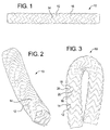
- the stent-graft 10 includes a stent 12 and a graft layer 14 adhered to the stent 12.
- the graft layer 14 may be made of various materials and adhered to the stent 12 in various ways.
- the graft layer 14 may be made from Thoralon, ultra high molecular weight polyethylene, ePTFE, PET, collagen materials, polyurethanes, woven materials, or other suitable graft materials.
- the graft layer 14 may be attached to the stent 12 by the use of sutures, dip coating, spraying, electro-spinning, or other suitable techniques.
- the stent 12 is preferably formed by a single wire 16 that is wound around the stent 12 body in a helical cylindrical pattern.
- the wire 16 may be a round cross-sectional wire 16 that is wound around a cylindrical mandrel 24 as described below.
- the wire 16 may have a rectangular cross-section that is formed by laser cutting the wire 16 structure from a cannula.
- the wire 16 may also be a wire ribbon having a rectangular cross-section.
- the wire 16 is made from an elastic material so that the stent 12 is self-expanding; however, a more ductile material could be used so that the stent 12 is balloon-expandable.
- elastic materials that may be used include nitinol and stainless steel.
- the wire 16 may also be draw filled tubing where a tube of one material surrounds a core of another material.
- the core may be made from a radiopaque material to make the stent 12 visible using external visualization equipment without the need for separate radiopaque markers.
- the outer tube of the draw filled tubing may also be made from nitinol in order to make the stent 12 self-expanding.
- various forms of nitinol may be used, such as quaternary nitinol where tungsten, barium or erbium is added to conventional nitinol to increase radiopacity and chromium or cobalt is added to improve radial stiffness.
- the wire 16 is bent back-and-forth along a helical pattern so that the wire 16 forms a series of bends 18 connecting circumferentially adjacent angular struts 20.
- the wire 16 is in a stress relaxed state in the helically wound cylindrical pattern, which may be achieved by heat setting the stent 12 pattern as described below.
- the length of each of the angular struts 20 is equal to each other so that, as shown in Figure 7 , circumferentially adjacent angular struts 20 are the same length.
- the stent 12 structure is unlike some prior art stent structures where the strut lengths are unequal to give the stent a staggered pattern.
- the stent 12 pattern may include angular struts 20 with unequal lengths at the ends of the stent 12 to permit the ends of the stent 12 to form circular, non-helical rings.
- the helically wound pattern of bends 18 and struts 20 is defined by a pitch angle A with respect to a plane transverse to the axis of the stent 12.
- the pitch angle A is from about 5° to about 20°. More preferably, the pitch angle A is from about 5° to about 15°. Most preferably, the pitch angle A is about 10°.
- an imaginary bisecting line 22 extends through each bend 18 connecting two circumferentially adjacent angular struts 20 and between the circumferentially adjacent struts 20.
- the bisecting line 22 is angled B from the longitudinal axis of the helically wound cylindrical pattern of the stent 12 from about 5° to about 20°. More preferably, the bisecting line 22 is angled B from about 5° to about 15°. Most preferably, the bisecting line 22 is angled B about 10°. However, it is preferable for angle A and angle B to be equal to each other.
- the width C of two circumferentially adjacent angular struts 20 be about 5.041 mm, and the height D of the angular struts 20 be about 3 mm from the outside of two opposing bends 18.
- the wire 16 preferably has a diameter of about 0.018 mm (0.007"), and the inner radius of the bends 18 is preferably about 0.02 mm (0.008"). These dimensions may be particularly suited to a stent with an 8 mm expanded diameter. However, the dimensions of the struts and bends may be designed to provide the desired radial force within the engineering strain limits of the material used so that the stent has the necessary fatigue resistance.
- the value of C would depend upon the stent diameter and the number of peaks and valleys incorporated in one helical revolution. Most preferably, the number of peaks is about 5 to about 12, although more peaks may be incorporated to reduce the radial force or increase the fatigue resistance of the stent structure.
- the stent 12 may be made by winding the wire 16 around a mandrel 24 with a circular cross-section.
- the mandrel 24 may have a series of pins 26 that extend radially outward from the mandrel 24.
- the helically wound cylindrical stent 12 pattern may then be formed by bending the wire 16 around the pins 26 and around the mandrel 24.
- the wire 16 may be heat set while it remains on the mandrel 24 so that the wire 16 retains the helically wound cylindrical pattern as the relaxed state of the wire 16.
- the wire 16 may then be removed from the mandrel 24 and a graft layer 14 may be attached to the stent 12 as described above.
- the helical stent 12 may have several advantages. As shown in Figures 1-2 and 5-6 , the stent 12 is helically wound into different respects. First, the zig-zag pattern of bends 18 and struts 20 wraps helically around the circumference of the stent 12 so that the wire 16 forms continuously connected rings along the length of the stent 12. Second, longitudinally adjacent bends 18 are nested within each other but are circumferentially offset from each other so that the bends 18 are helically arranged relative to each other. Because the stent 12 does not have longitudinal connectors connecting adjacent rings, the stent 12 may be extremely flexible.
- the stent 12 may have a high kink resistance, which may allow the stent 12 to be bent as much as 180° without kinking.
- the stent 12 also has a high proportion of open area through the stent 12 wall, which may be desirable for flexibility, fatigue and decreased vessel wall contact.
- the stent 12 may also have increased axial flexibility, which may permit the stent 12 to change length as much as 50% or more to accommodate shape changes in the vessel as a person moves his/her body.
- the helical pattern of the wire 16 may also impart a swirling motion to blood flowing through the stent 12, which may improve blood flow through the stent 12.
- the delivery profile of the stent 12 may also be improved, since angular struts 20 disposed diametrically opposite of each other may not be directly aligned with each other, which may permit the struts 20 to diametrically nest into each other to provide a lower profile compressed state.
Landscapes
- Health & Medical Sciences (AREA)
- Engineering & Computer Science (AREA)
- Biomedical Technology (AREA)
- Heart & Thoracic Surgery (AREA)
- Public Health (AREA)
- Transplantation (AREA)
- Cardiology (AREA)
- Veterinary Medicine (AREA)
- Oral & Maxillofacial Surgery (AREA)
- Vascular Medicine (AREA)
- Life Sciences & Earth Sciences (AREA)
- Animal Behavior & Ethology (AREA)
- General Health & Medical Sciences (AREA)
- Gastroenterology & Hepatology (AREA)
- Pulmonology (AREA)
- Prostheses (AREA)
- Media Introduction/Drainage Providing Device (AREA)
Claims (15)
- Stent (12), umfassend:einen einzelnen Draht (16), der in einem zylindrischen Muster spiralförmig entlang eines erheblichen Abschnitts des Stents gewickelt ist;wobei der Draht von einer Reihe von winkelförmigen Streben (20) und Biegungen (18), welche umfangsmäßig benachbarte winkelförmige Streben verbinden, definiert wird;wobei jede der winkelförmigen Streben in dem spiralförmig gewickelten zylindrischen Muster gleiche Längen aufweisen;wobei umfangsmäßig benachbarte Biegungen einen Steigungswinkel (A) des spiralförmig gewickelten zylindrischen Musters bezüglich einer Ebene quer zur Achse des Stents definieren; undwobei die Biegungen und die winkelförmigen Streben Winkelhalbierende (22) definieren, die sich durch die Biegungen und zwischen umfangsmäßig benachbarten winkelförmigen Streben erstrecken, wobei die Winkelhalbierenden ungefähr 5° bis ungefähr 20° bezüglich einer Längsachse, die sich durch das spiralförmig gewickelte zylindrische Muster erstreckt, abgewinkelt (B) sind, und in Längsrichtung benachbarte Biegungen ineinander geschachtelt sind.
- Stent nach Anspruch 1, worin der Draht (16) elastisch ist, wobei der Stent dadurch selbstexpandierend ist.
- Stent nach Anspruch 1 oder 2, worin die Winkelhalbierenden (22) ungefähr 5° bis ungefähr 15° bezüglich der Längsachse abgewinkelt sind.
- Stent nach Anspruch 1 oder 2, worin die Winkelhalbierenden (22) ungefähr 10° bezüglich der Längsachse abgewinkelt sind.
- Stent nach einem der vorhergehenden Ansprüche, worin der Steigungswinkel (A) ungefähr 5° bis ungefähr 20° beträgt.
- Stent nach einem der Ansprüche 1 bis 4, worin der Steigungswinkel (A) ungefähr 10° beträgt.
- Stent nach einem der vorhergehenden Ansprüche, worin der Draht (16) einen runden Querschnitt aufweist.
- Stent nach einem der vorhergehenden Ansprüche, worin das spiralförmig gewickelte zylindrische Muster einen entspannten Zustand des Drahts umfasst.
- Stent nach Anspruch 1, worin die Winkelhalbierenden (22) allgemein gleich zu dem Steigungswinkel (A) abgewinkelt (B) sind, der Draht (16) elastisch ist, der Stent dadurch selbstexpandierend ist, der Draht einen runden Querschnitt aufweist und das spiralförmig gewickelte zylindrische Muster einen entspannten Zustand des Drahts umfasst.
- Stent nach Anspruch 9, worin die Winkelhalbierenden (22) ungefähr 5° bis ungefähr 15° bezüglich der Längsachse abgewinkelt (B) sind.
- Stent nach Anspruch 10, worin die Winkelhalbierenden (22) ungefähr 10° bezüglich der Längsachse abgewinkelt sind und der Steigungswinkel (A) ungefähr 10° beträgt.
- Stent nach einem der vorhergehenden Ansprüche, worin der Draht (16) DFT-Draht (Drawn Filled Tubing Draht) mit einem röntgenopaken Kern umfasst.
- Stent nach Anspruch 12, worin der DFT-Draht (16) ferner einen Nitinolschlauch umfasst, der den röntgenopaken Kern umgibt.
- Stent nach einem der vorhergehenden Ansprüche, ferner umfassend eine Stentgraftprothese (14), die an dem spiralförmig gewickelten zylindrischen Muster befestigt ist.
- Verfahren zur Herstellung eines Stents (12), umfassend:Wickeln eines einzelnen Drahts (16) spiralförmig um einen Mandrin (24) mit einem kreisförmigen Querschnitt zur Bildung eines zylindrischen Musters entlang eines erheblichen Abschnitts des Stents;wobei der Mandrin eine Reihe von sich radial erstreckenden Stiften (26) umfasst, um die der Draht gewickelt wird, um den Draht in eine Reihe von winkelförmigen Streben (20) und Biegungen (18), welche umfangsmäßig benachbarte winkelförmige Streben verbinden, zu wickeln;wobei jede der winkelförmigen Streben in dem spiralförmig gewickelten zylindrischen Muster gleiche Längen aufweisen;wobei umfangsmäßig benachbarte Biegungen einen Steigungswinkel (A) des spiralförmig gewickelten zylindrischen Musters definieren; undwobei die Biegungen und die winkelförmigen Streben Winkelhalbierende (22) definieren, die sich durch die Biegungen und zwischen umfangsmäßig benachbarten winkelförmigen Streben erstrecken, wobei die Winkelhalbierenden ungefähr 5° bis ungefähr 20° bezüglich einer Längsachse, die sich durch das spiralförmig gewickelte zylindrische Muster erstreckt, abgewinkelt (B) sind, und in Längsrichtung benachbarte Biegungen ineinander geschachtelt sind.
Priority Applications (1)
| Application Number | Priority Date | Filing Date | Title |
|---|---|---|---|
| EP16150460.0A EP3023080B1 (de) | 2011-06-24 | 2012-06-25 | Stentimplantat |
Applications Claiming Priority (1)
| Application Number | Priority Date | Filing Date | Title |
|---|---|---|---|
| US201161500986P | 2011-06-24 | 2011-06-24 |
Related Child Applications (1)
| Application Number | Title | Priority Date | Filing Date |
|---|---|---|---|
| EP16150460.0A Division EP3023080B1 (de) | 2011-06-24 | 2012-06-25 | Stentimplantat |
Publications (2)
| Publication Number | Publication Date |
|---|---|
| EP2537491A1 EP2537491A1 (de) | 2012-12-26 |
| EP2537491B1 true EP2537491B1 (de) | 2016-01-20 |
Family
ID=46465061
Family Applications (2)
| Application Number | Title | Priority Date | Filing Date |
|---|---|---|---|
| EP12173460.2A Active EP2537491B1 (de) | 2011-06-24 | 2012-06-25 | Spiralförmiger Stent |
| EP16150460.0A Active EP3023080B1 (de) | 2011-06-24 | 2012-06-25 | Stentimplantat |
Family Applications After (1)
| Application Number | Title | Priority Date | Filing Date |
|---|---|---|---|
| EP16150460.0A Active EP3023080B1 (de) | 2011-06-24 | 2012-06-25 | Stentimplantat |
Country Status (4)
| Country | Link |
|---|---|
| US (1) | US10271974B2 (de) |
| EP (2) | EP2537491B1 (de) |
| JP (1) | JP5719327B2 (de) |
| AU (1) | AU2012203620B9 (de) |
Families Citing this family (26)
| Publication number | Priority date | Publication date | Assignee | Title |
|---|---|---|---|---|
| US9510930B2 (en) | 2008-10-22 | 2016-12-06 | Contego Medical, Llc | Angioplasty device with embolic filter |
| US9707071B2 (en) | 2004-11-24 | 2017-07-18 | Contego Medical Llc | Percutaneous transluminal angioplasty device with integral embolic filter |
| EP2167152B1 (de) | 2007-06-13 | 2012-08-01 | Boston Scientific Scimed, Inc. | Anti-migrations-merkmale und geometrie für einen polymerstent mit formgedächtnis |
| US10028747B2 (en) | 2008-05-01 | 2018-07-24 | Aneuclose Llc | Coils with a series of proximally-and-distally-connected loops for occluding a cerebral aneurysm |
| US10716573B2 (en) | 2008-05-01 | 2020-07-21 | Aneuclose | Janjua aneurysm net with a resilient neck-bridging portion for occluding a cerebral aneurysm |
| WO2010041039A1 (en) | 2008-10-10 | 2010-04-15 | Veryan Medical Limited | A medical device suitable for location in a body lumen |
| US9539120B2 (en) * | 2008-10-10 | 2017-01-10 | Veryan Medical Ltd. | Medical device suitable for location in a body lumen |
| US10456276B2 (en) | 2009-05-08 | 2019-10-29 | Veryan Medical Limited | Medical device suitable for location in a body lumen |
| US9358140B1 (en) | 2009-11-18 | 2016-06-07 | Aneuclose Llc | Stent with outer member to embolize an aneurysm |
| US9629735B2 (en) * | 2012-11-16 | 2017-04-25 | W. L. Gore & Associates, Inc. | Flexible endoluminal device |
| US20140277383A1 (en) * | 2013-03-15 | 2014-09-18 | Contego Medical, Llc | Expandable stent having a constant length |
| CN108403257B (zh) * | 2014-05-30 | 2021-03-16 | 安德乐吉克斯有限责任公司 | 使用膨胀式填充结构的模块化支架移植物系统和方法 |
| CN106794061B (zh) * | 2014-10-09 | 2019-11-22 | 波士顿科学国际有限公司 | 具有引流特征的胰管支架 |
| EP3247441B1 (de) | 2015-01-23 | 2023-11-08 | Contego Medical, Inc. | Interventionelle vorrichtung mit integriertem embolischem filter |
| WO2016183128A1 (en) * | 2015-05-11 | 2016-11-17 | Trivascular, Inc. | Stent-graft with improved flexibility |
| EP3127561A1 (de) * | 2015-08-05 | 2017-02-08 | Jenpolymer Materials UG & Co. KG | Medizinisches implantat basierend auf nanocellulose |
| AU2017335843B2 (en) * | 2016-09-29 | 2023-01-05 | Merit Medical Systems, Inc. | Pliant members for receiving and aiding in the deployment of vascular prostheses |
| KR20180075945A (ko) * | 2016-12-27 | 2018-07-05 | 심민혁 | 스텐트 |
| US10335264B2 (en) * | 2017-03-10 | 2019-07-02 | Byung Choo Moon | Vascular graft |
| CN107126299A (zh) * | 2017-06-08 | 2017-09-05 | 有研医疗器械(北京)有限公司 | 一种高柔顺型胸主动脉覆膜支架及其定型模具和方法 |
| US10238466B2 (en) * | 2017-06-15 | 2019-03-26 | Cook Medical Technologies Llc | Method of making a superelastic medical device with a radiopaque marker |
| WO2019213120A1 (en) | 2018-05-02 | 2019-11-07 | W. L. Gore & Associates, Inc. | Expansion members for implantable devices and associated systems and methods |
| CN108888391A (zh) * | 2018-07-12 | 2018-11-27 | 北京龙慧珩医疗科技发展有限公司 | 一种单丝非交叉支架 |
| CN114701104A (zh) * | 2022-04-29 | 2022-07-05 | 深圳市库珀科技发展有限公司 | 覆膜支架及其单丝压入装置 |
| CN115153991B (zh) * | 2022-08-25 | 2025-07-25 | 首都医科大学附属北京天坛医院 | 一种脑血管闭塞病变专用的自膨式血管支架 |
| DE102024111934A1 (de) * | 2024-04-29 | 2025-10-30 | Acandis Gmbh | Medizinische Vorrichtung; Verfahren zur Herstellung einer medizinischen Vorrichtung |
Family Cites Families (138)
| Publication number | Priority date | Publication date | Assignee | Title |
|---|---|---|---|---|
| FR2521014B1 (fr) | 1982-02-05 | 1988-06-03 | Matburn Holdings Ltd | Instrument chirurgical tubulaire, notamment catheter de thrombectomie |
| US6685696B2 (en) | 1987-09-30 | 2004-02-03 | Lake Region Manufacturing, Inc. | Hollow lumen cable apparatus |
| US4886062A (en) | 1987-10-19 | 1989-12-12 | Medtronic, Inc. | Intravascular radially expandable stent and method of implant |
| US5133732A (en) | 1987-10-19 | 1992-07-28 | Medtronic, Inc. | Intravascular stent |
| US5226913A (en) | 1988-09-01 | 1993-07-13 | Corvita Corporation | Method of making a radially expandable prosthesis |
| US5019090A (en) * | 1988-09-01 | 1991-05-28 | Corvita Corporation | Radially expandable endoprosthesis and the like |
| US5269751A (en) | 1988-09-21 | 1993-12-14 | Josef Kaliman | Thrombectomy catheter for enlarging an artery |
| CA2049973C (en) | 1990-02-28 | 2002-12-24 | Rodney G. Wolff | Intralumenal drug eluting prosthesis |
| US5360443A (en) | 1990-06-11 | 1994-11-01 | Barone Hector D | Aortic graft for repairing an abdominal aortic aneurysm |
| DE9117152U1 (de) | 1990-10-09 | 1996-07-11 | Cook Inc., Bloomington, Ind. | Stent |
| US5527354A (en) | 1991-06-28 | 1996-06-18 | Cook Incorporated | Stent formed of half-round wire |
| USD390957S (en) | 1992-03-09 | 1998-02-17 | Cook Incorporated | Implantable intravascular stent |
| USD484979S1 (en) | 1991-06-28 | 2004-01-06 | Cook Incorporated | Implantable intravascular stent |
| US5314472A (en) | 1991-10-01 | 1994-05-24 | Cook Incorporated | Vascular stent |
| US5443498A (en) | 1991-10-01 | 1995-08-22 | Cook Incorporated | Vascular stent and method of making and implanting a vacsular stent |
| FR2685190B1 (fr) | 1991-12-23 | 1998-08-07 | Jean Marie Lefebvre | Dispositif rotatif d'atherectomie ou de thrombectomie a developpement transversal centrifuge. |
| US5316023A (en) | 1992-01-08 | 1994-05-31 | Expandable Grafts Partnership | Method for bilateral intra-aortic bypass |
| US5507767A (en) | 1992-01-15 | 1996-04-16 | Cook Incorporated | Spiral stent |
| US5571166A (en) | 1992-03-19 | 1996-11-05 | Medtronic, Inc. | Method of making an intraluminal stent |
| US5370683A (en) | 1992-03-25 | 1994-12-06 | Cook Incorporated | Vascular stent |
| US5370653A (en) | 1993-07-22 | 1994-12-06 | Micro Therapeutics, Inc. | Thrombectomy method and apparatus |
| US6689158B1 (en) | 1993-09-30 | 2004-02-10 | Endogad Research Pty Limited | Intraluminal graft |
| EP0676937B1 (de) | 1993-09-30 | 2004-03-17 | Endogad Research PTY Limited | Intraluminales transplantat |
| US5476506A (en) | 1994-02-08 | 1995-12-19 | Ethicon, Inc. | Bi-directional crimped graft |
| US5575816A (en) | 1994-08-12 | 1996-11-19 | Meadox Medicals, Inc. | High strength and high density intraluminal wire stent |
| US6331188B1 (en) * | 1994-08-31 | 2001-12-18 | Gore Enterprise Holdings, Inc. | Exterior supported self-expanding stent-graft |
| US20020156523A1 (en) | 1994-08-31 | 2002-10-24 | Lilip Lau | Exterior supported self-expanding stent-graft |
| WO1996021404A1 (en) | 1995-01-14 | 1996-07-18 | Prograft, Medical, Inc. | Kink-resistant stent-graft |
| US5575818A (en) * | 1995-02-14 | 1996-11-19 | Corvita Corporation | Endovascular stent with locking ring |
| US5824037A (en) * | 1995-10-03 | 1998-10-20 | Medtronic, Inc. | Modular intraluminal prostheses construction and methods |
| US5591195A (en) | 1995-10-30 | 1997-01-07 | Taheri; Syde | Apparatus and method for engrafting a blood vessel |
| US6042605A (en) * | 1995-12-14 | 2000-03-28 | Gore Enterprose Holdings, Inc. | Kink resistant stent-graft |
| US5865723A (en) | 1995-12-29 | 1999-02-02 | Ramus Medical Technologies | Method and apparatus for forming vascular prostheses |
| US5895398A (en) | 1996-02-02 | 1999-04-20 | The Regents Of The University Of California | Method of using a clot capture coil |
| DE69702281T2 (de) * | 1996-04-16 | 2001-02-22 | Medtronic, Inc. | Geschweisster sinuswellenförmiger Stent |
| WO1998020810A1 (en) | 1996-11-12 | 1998-05-22 | Medtronic, Inc. | Flexible, radially expansible luminal prostheses |
| US6352561B1 (en) | 1996-12-23 | 2002-03-05 | W. L. Gore & Associates | Implant deployment apparatus |
| US6551350B1 (en) | 1996-12-23 | 2003-04-22 | Gore Enterprise Holdings, Inc. | Kink resistant bifurcated prosthesis |
| US5925061A (en) * | 1997-01-13 | 1999-07-20 | Gore Enterprise Holdings, Inc. | Low profile vascular stent |
| US6491619B1 (en) | 1997-01-31 | 2002-12-10 | Endologix, Inc | Radiation delivery catheters and dosimetry methods |
| US5782742A (en) | 1997-01-31 | 1998-07-21 | Cardiovascular Dynamics, Inc. | Radiation delivery balloon |
| US6951572B1 (en) | 1997-02-20 | 2005-10-04 | Endologix, Inc. | Bifurcated vascular graft and method and apparatus for deploying same |
| US6090128A (en) | 1997-02-20 | 2000-07-18 | Endologix, Inc. | Bifurcated vascular graft deployment device |
| US6137060A (en) | 1997-05-02 | 2000-10-24 | General Science And Technology Corp | Multifilament drawn radiopaque highly elastic cables and methods of making the same |
| US6278057B1 (en) | 1997-05-02 | 2001-08-21 | General Science And Technology Corp. | Medical devices incorporating at least one element made from a plurality of twisted and drawn wires at least one of the wires being a nickel-titanium alloy wire |
| US6191365B1 (en) | 1997-05-02 | 2001-02-20 | General Science And Technology Corp | Medical devices incorporating at least one element made from a plurality of twisted and drawn wires |
| US5968057A (en) | 1997-06-18 | 1999-10-19 | Taheri; Syde A. | Apparatus for removing a blood clot from a vessel |
| US6635080B1 (en) | 1997-06-19 | 2003-10-21 | Vascutek Limited | Prosthesis for repair of body passages |
| US7037316B2 (en) | 1997-07-24 | 2006-05-02 | Mcguckin Jr James F | Rotational thrombectomy device |
| US6245103B1 (en) * | 1997-08-01 | 2001-06-12 | Schneider (Usa) Inc | Bioabsorbable self-expanding stent |
| US5984965A (en) | 1997-08-28 | 1999-11-16 | Urosurge, Inc. | Anti-reflux reinforced stent |
| US6156062A (en) | 1997-12-03 | 2000-12-05 | Ave Connaught | Helically wrapped interlocking stent |
| EP1049420B8 (de) | 1998-01-26 | 2006-01-11 | Anson Medical Limited | Verstärktes implantat |
| EP1056515A1 (de) | 1998-02-19 | 2000-12-06 | Radiance Medical Systems Inc. | Radioaktiver stent |
| US6077296A (en) | 1998-03-04 | 2000-06-20 | Endologix, Inc. | Endoluminal vascular prosthesis |
| US6511492B1 (en) | 1998-05-01 | 2003-01-28 | Microvention, Inc. | Embolectomy catheters and methods for treating stroke and other small vessel thromboembolic disorders |
| US6159239A (en) | 1998-08-14 | 2000-12-12 | Prodesco, Inc. | Woven stent/graft structure |
| US6019779A (en) | 1998-10-09 | 2000-02-01 | Intratherapeutics Inc. | Multi-filar coil medical stent |
| CN1287478A (zh) | 1998-11-12 | 2001-03-14 | 先进心血管系统公司 | 具有非均匀结构的扩张装置 |
| US6325820B1 (en) | 1998-11-16 | 2001-12-04 | Endotex Interventional Systems, Inc. | Coiled-sheet stent-graft with exo-skeleton |
| US6540780B1 (en) * | 1998-11-23 | 2003-04-01 | Medtronic, Inc. | Porous synthetic vascular grafts with oriented ingrowth channels |
| US6197049B1 (en) | 1999-02-17 | 2001-03-06 | Endologix, Inc. | Articulating bifurcation graft |
| JP4189127B2 (ja) | 1998-12-11 | 2008-12-03 | エンドロジックス、インク | 管腔内人工血管 |
| US6660030B2 (en) | 1998-12-11 | 2003-12-09 | Endologix, Inc. | Bifurcation graft deployment catheter |
| US6187036B1 (en) | 1998-12-11 | 2001-02-13 | Endologix, Inc. | Endoluminal vascular prosthesis |
| US6733523B2 (en) | 1998-12-11 | 2004-05-11 | Endologix, Inc. | Implantable vascular graft |
| EP1073385A2 (de) | 1999-01-22 | 2001-02-07 | Gore Enterprise Holdings, Inc. | Gallengangstent |
| US7018401B1 (en) | 1999-02-01 | 2006-03-28 | Board Of Regents, The University Of Texas System | Woven intravascular devices and methods for making the same and apparatus for delivery of the same |
| IL128938A0 (en) | 1999-03-11 | 2000-02-17 | Mind Guard Ltd | Implantable stroke treating device |
| US6261316B1 (en) | 1999-03-11 | 2001-07-17 | Endologix, Inc. | Single puncture bifurcation graft deployment system |
| US6986784B1 (en) | 1999-05-14 | 2006-01-17 | C. R. Bard, Inc. | Implant anchor systems |
| US6364904B1 (en) | 1999-07-02 | 2002-04-02 | Scimed Life Systems, Inc. | Helically formed stent/graft assembly |
| US6440161B1 (en) | 1999-07-07 | 2002-08-27 | Endologix, Inc. | Dual wire placement catheter |
| US7320697B2 (en) | 1999-07-30 | 2008-01-22 | Boston Scientific Scimed, Inc. | One piece loop and coil |
| US6454775B1 (en) | 1999-12-06 | 2002-09-24 | Bacchus Vascular Inc. | Systems and methods for clot disruption and retrieval |
| US6280466B1 (en) | 1999-12-03 | 2001-08-28 | Teramed Inc. | Endovascular graft system |
| US7169187B2 (en) | 1999-12-22 | 2007-01-30 | Ethicon, Inc. | Biodegradable stent |
| US6338739B1 (en) | 1999-12-22 | 2002-01-15 | Ethicon, Inc. | Biodegradable stent |
| US6312458B1 (en) | 2000-01-19 | 2001-11-06 | Scimed Life Systems, Inc. | Tubular structure/stent/stent securement member |
| GB0001102D0 (en) | 2000-01-19 | 2000-03-08 | Sulzer Vascutek Ltd | Prosthesis |
| US6537198B1 (en) | 2000-03-21 | 2003-03-25 | Myocor, Inc. | Splint assembly for improving cardiac function in hearts, and method for implanting the splint assembly |
| US20010031981A1 (en) | 2000-03-31 | 2001-10-18 | Evans Michael A. | Method and device for locating guidewire and treating chronic total occlusions |
| US6974473B2 (en) | 2000-06-30 | 2005-12-13 | Vascular Architects, Inc. | Function-enhanced thrombolytic AV fistula and method |
| JP2002035135A (ja) | 2000-07-31 | 2002-02-05 | Manii Kk | ステント及びステントの製造方法 |
| US6709452B1 (en) * | 2000-08-21 | 2004-03-23 | Linvatec Biomaterial Oy | Biodegradable surgical implants |
| JP4196673B2 (ja) | 2000-11-15 | 2008-12-17 | エンドロジックス、インク | チューブ状ワイヤー・サポート |
| EP1245202B1 (de) | 2001-03-27 | 2004-08-04 | William Cook Europe ApS | Gefässtransplantat für die Aorta |
| GB0107910D0 (en) | 2001-03-29 | 2001-05-23 | Isis Innovation | Deployable stent |
| US20060265052A1 (en) | 2001-03-29 | 2006-11-23 | Isis Innovation Limited | Deployable stent |
| AUPR847301A0 (en) | 2001-10-26 | 2001-11-15 | Cook Incorporated | Endoluminal prostheses for curved lumens |
| US20030135265A1 (en) | 2002-01-04 | 2003-07-17 | Stinson Jonathan S. | Prostheses implantable in enteral vessels |
| US6926725B2 (en) | 2002-04-04 | 2005-08-09 | Rex Medical, L.P. | Thrombectomy device with multi-layered rotational wire |
| WO2003092549A2 (en) | 2002-05-06 | 2003-11-13 | Abbott Laboratories | Endoprosthesis for controlled contraction and expansion |
| CA2486363A1 (en) | 2002-05-28 | 2003-12-04 | The Cleveland Clinic Foundation | Minimally invasive treatment system for aortic aneurysms |
| US20040019375A1 (en) | 2002-07-26 | 2004-01-29 | Scimed Life Systems, Inc. | Sectional crimped graft |
| US6984243B2 (en) | 2002-07-30 | 2006-01-10 | Cordis Corporation | Abrasion resistant vascular graft |
| US6878162B2 (en) | 2002-08-30 | 2005-04-12 | Edwards Lifesciences Ag | Helical stent having improved flexibility and expandability |
| US20040193141A1 (en) | 2003-02-14 | 2004-09-30 | Leopold Eric W. | Intravascular flow modifier and reinforcement device and deployment system for same |
| US7763012B2 (en) | 2003-09-02 | 2010-07-27 | St. Jude Medical, Cardiology Division, Inc. | Devices and methods for crossing a chronic total occlusion |
| US8088156B2 (en) | 2003-10-07 | 2012-01-03 | Cordis Corporation | Graft material attachment device and method |
| US20050085894A1 (en) | 2003-10-16 | 2005-04-21 | Kershner James R. | High strength and lubricious materials for vascular grafts |
| US20050131515A1 (en) * | 2003-12-16 | 2005-06-16 | Cully Edward H. | Removable stent-graft |
| US20050137677A1 (en) | 2003-12-17 | 2005-06-23 | Rush Scott L. | Endovascular graft with differentiable porosity along its length |
| US7763011B2 (en) | 2003-12-22 | 2010-07-27 | Boston Scientific Scimed, Inc. | Variable density braid stent |
| US7766960B2 (en) * | 2004-04-30 | 2010-08-03 | Novostent Corporation | Delivery catheter that controls foreshortening of ribbon-type prostheses and methods of making and use |
| US20060004436A1 (en) | 2004-07-02 | 2006-01-05 | Amarant Paul D | Stent having arcuate struts |
| US7318835B2 (en) | 2004-07-20 | 2008-01-15 | Medtronic Vascular, Inc. | Endoluminal prosthesis having expandable graft sections |
| US20060085065A1 (en) * | 2004-10-15 | 2006-04-20 | Krause Arthur A | Stent with auxiliary treatment structure |
| US7462192B2 (en) * | 2004-11-10 | 2008-12-09 | Boston Scientific Scimed, Inc. | Atraumatic stent with reduced deployment force, method for making the same and method and apparatus for deploying and positioning the stent |
| CN2817768Y (zh) | 2005-05-24 | 2006-09-20 | 微创医疗器械(上海)有限公司 | 一种覆膜支架的主体支架段及覆膜支架 |
| US7963988B2 (en) | 2005-06-23 | 2011-06-21 | Boston Scientific Scimed, Inc. | ePTFE lamination—resizing ePTFE tubing |
| EP1965730A4 (de) * | 2005-12-30 | 2009-06-17 | Bard Inc C R | Stent mit bioresorbierbarem konnektor und entsprechende verfahren |
| EP1991164B1 (de) | 2006-02-28 | 2017-06-14 | Angiomed GmbH & Co. Medizintechnik KG | Flexibles dehnbares stenttransplantat |
| US8025693B2 (en) | 2006-03-01 | 2011-09-27 | Boston Scientific Scimed, Inc. | Stent-graft having flexible geometries and methods of producing the same |
| US20070208409A1 (en) * | 2006-03-01 | 2007-09-06 | Boston Scientific Scimed, Inc. | Flexible stent-graft devices and methods of producing the same |
| US8585753B2 (en) | 2006-03-04 | 2013-11-19 | John James Scanlon | Fibrillated biodegradable prosthesis |
| US20070219618A1 (en) * | 2006-03-17 | 2007-09-20 | Cully Edward H | Endoprosthesis having multiple helically wound flexible framework elements |
| WO2007137184A2 (en) | 2006-05-18 | 2007-11-29 | Applied Medical Resources Corporation | Method of making medical tubing having variable characteristics using thermal winding |
| US8500793B2 (en) * | 2006-09-07 | 2013-08-06 | C. R. Bard, Inc. | Helical implant having different ends |
| JP2010504820A (ja) | 2006-09-28 | 2010-02-18 | クック・インコーポレイテッド | 胸部大動脈瘤を修復するための装置および方法 |
| US8425585B2 (en) | 2006-10-24 | 2013-04-23 | Cook Medical Technologies Llc | Thoracic arch stent graft and method of delivery |
| DE102007008185A1 (de) | 2007-02-13 | 2008-08-14 | Aesculap Ag & Co. Kg | Non woven Gefäßprothese und Verfahren zu ihrer Herstellung |
| US8623070B2 (en) * | 2007-03-08 | 2014-01-07 | Thomas O. Bales | Tapered helical stent and method for manufacturing the stent |
| AU2007350131B2 (en) * | 2007-03-23 | 2013-05-02 | Invatec Technology Center Gmbh | Endoluminal prosthesis |
| US20080262594A1 (en) | 2007-04-19 | 2008-10-23 | Medtronic Vascular, Inc. | Stent Graft Sealing System and Method |
| US10154917B2 (en) | 2007-06-22 | 2018-12-18 | C. R. Bard, Inc. | Helical and segmented stent-graft |
| US20080319534A1 (en) | 2007-06-22 | 2008-12-25 | Medtronic Vascular, Inc. | Stent With Improved Mechanical Properties |
| US20080319535A1 (en) | 2007-06-25 | 2008-12-25 | Medtronic Vascular, Inc. | Vascular Stent and Method of Making Vascular Stent |
| US9107741B2 (en) | 2007-11-01 | 2015-08-18 | Cook Medical Technologies Llc | Flexible stent graft |
| JP2011502636A (ja) * | 2007-11-06 | 2011-01-27 | メドトロニック カルディオ ヴァスキュラー インコーポレイテッド | 改善された機械特性を有するステント |
| US8623071B2 (en) * | 2008-01-07 | 2014-01-07 | DePuy Synthes Products, LLC | Radiopaque super-elastic intravascular stent |
| US8642063B2 (en) * | 2008-08-22 | 2014-02-04 | Cook Medical Technologies Llc | Implantable medical device coatings with biodegradable elastomer and releasable taxane agent |
| US8394138B2 (en) * | 2008-09-05 | 2013-03-12 | Cook Medical Technologies Llc | Multi-strand helical stent |
| US8641753B2 (en) * | 2009-01-31 | 2014-02-04 | Cook Medical Technologies Llc | Preform for and an endoluminal prosthesis |
| WO2011034795A1 (en) * | 2009-09-18 | 2011-03-24 | Medtronic Vascular Inc. | Methods for forming an orthogonal end on a helical stent |
| US20110067471A1 (en) * | 2009-09-18 | 2011-03-24 | Medtronic Vascular, Inc. | Method and Apparatus for Creating Formed Elements Used to Make Wound Stents |
| WO2011034768A1 (en) * | 2009-09-21 | 2011-03-24 | Boston Scientific Scimed, Inc. | Integrated stent retrieval loop adapted for snare removal and/or optimized purse stringing |
| US8474120B2 (en) * | 2009-10-09 | 2013-07-02 | W. L. Gore & Associates, Inc. | Bifurcated highly conformable medical device branch access |
-
2012
- 2012-06-21 AU AU2012203620A patent/AU2012203620B9/en active Active
- 2012-06-22 US US13/530,685 patent/US10271974B2/en active Active
- 2012-06-22 JP JP2012140374A patent/JP5719327B2/ja active Active
- 2012-06-25 EP EP12173460.2A patent/EP2537491B1/de active Active
- 2012-06-25 EP EP16150460.0A patent/EP3023080B1/de active Active
Also Published As
| Publication number | Publication date |
|---|---|
| JP5719327B2 (ja) | 2015-05-13 |
| AU2012203620A1 (en) | 2013-01-17 |
| EP3023080B1 (de) | 2018-06-13 |
| US20120330402A1 (en) | 2012-12-27 |
| JP2013006029A (ja) | 2013-01-10 |
| EP2537491A1 (de) | 2012-12-26 |
| AU2012203620B2 (en) | 2014-09-11 |
| AU2012203620B9 (en) | 2014-10-02 |
| EP3023080A1 (de) | 2016-05-25 |
| US10271974B2 (en) | 2019-04-30 |
Similar Documents
| Publication | Publication Date | Title |
|---|---|---|
| EP2537491B1 (de) | Spiralförmiger Stent | |
| EP2875798B1 (de) | Geflochtener stent | |
| US6270524B1 (en) | Flexible, radially expansible luminal prostheses | |
| EP1773248B1 (de) | Stent mit endglied mit einer seitlichen verlängerung | |
| US8092510B2 (en) | Retention wire for self-expanding stent | |
| US9839538B2 (en) | Method for making a flexible stent-graft | |
| AU2006259293B2 (en) | Intraluminal device with unsymmetric tapered beams | |
| US7651523B2 (en) | Intraluminal device with flexible regions | |
| US20130073052A1 (en) | Stent with improved end cell structural member | |
| US20230011734A1 (en) | Devices and systems for improving stent performance | |
| EP2572682B1 (de) | Verbesserte Stent-Geometrie |
Legal Events
| Date | Code | Title | Description |
|---|---|---|---|
| PUAI | Public reference made under article 153(3) epc to a published international application that has entered the european phase |
Free format text: ORIGINAL CODE: 0009012 |
|
| AK | Designated contracting states |
Kind code of ref document: A1 Designated state(s): AL AT BE BG CH CY CZ DE DK EE ES FI FR GB GR HR HU IE IS IT LI LT LU LV MC MK MT NL NO PL PT RO RS SE SI SK SM TR |
|
| AX | Request for extension of the european patent |
Extension state: BA ME |
|
| 17P | Request for examination filed |
Effective date: 20130403 |
|
| 17Q | First examination report despatched |
Effective date: 20130815 |
|
| GRAP | Despatch of communication of intention to grant a patent |
Free format text: ORIGINAL CODE: EPIDOSNIGR1 |
|
| INTG | Intention to grant announced |
Effective date: 20150109 |
|
| GRAC | Information related to communication of intention to grant a patent modified |
Free format text: ORIGINAL CODE: EPIDOSCIGR1 |
|
| INTG | Intention to grant announced |
Effective date: 20150723 |
|
| GRAS | Grant fee paid |
Free format text: ORIGINAL CODE: EPIDOSNIGR3 |
|
| GRAA | (expected) grant |
Free format text: ORIGINAL CODE: 0009210 |
|
| AK | Designated contracting states |
Kind code of ref document: B1 Designated state(s): AL AT BE BG CH CY CZ DE DK EE ES FI FR GB GR HR HU IE IS IT LI LT LU LV MC MK MT NL NO PL PT RO RS SE SI SK SM TR |
|
| REG | Reference to a national code |
Ref country code: GB Ref legal event code: FG4D |
|
| REG | Reference to a national code |
Ref country code: CH Ref legal event code: EP |
|
| REG | Reference to a national code |
Ref country code: IE Ref legal event code: FG4D |
|
| REG | Reference to a national code |
Ref country code: AT Ref legal event code: REF Ref document number: 771358 Country of ref document: AT Kind code of ref document: T Effective date: 20160215 |
|
| REG | Reference to a national code |
Ref country code: DE Ref legal event code: R096 Ref document number: 602012014051 Country of ref document: DE |
|
| REG | Reference to a national code |
Ref country code: LT Ref legal event code: MG4D Ref country code: NL Ref legal event code: MP Effective date: 20160120 |
|
| REG | Reference to a national code |
Ref country code: AT Ref legal event code: MK05 Ref document number: 771358 Country of ref document: AT Kind code of ref document: T Effective date: 20160120 |
|
| PG25 | Lapsed in a contracting state [announced via postgrant information from national office to epo] |
Ref country code: NL Free format text: LAPSE BECAUSE OF FAILURE TO SUBMIT A TRANSLATION OF THE DESCRIPTION OR TO PAY THE FEE WITHIN THE PRESCRIBED TIME-LIMIT Effective date: 20160120 |
|
| PG25 | Lapsed in a contracting state [announced via postgrant information from national office to epo] |
Ref country code: FI Free format text: LAPSE BECAUSE OF FAILURE TO SUBMIT A TRANSLATION OF THE DESCRIPTION OR TO PAY THE FEE WITHIN THE PRESCRIBED TIME-LIMIT Effective date: 20160120 Ref country code: IT Free format text: LAPSE BECAUSE OF FAILURE TO SUBMIT A TRANSLATION OF THE DESCRIPTION OR TO PAY THE FEE WITHIN THE PRESCRIBED TIME-LIMIT Effective date: 20160120 Ref country code: GR Free format text: LAPSE BECAUSE OF FAILURE TO SUBMIT A TRANSLATION OF THE DESCRIPTION OR TO PAY THE FEE WITHIN THE PRESCRIBED TIME-LIMIT Effective date: 20160421 Ref country code: NO Free format text: LAPSE BECAUSE OF FAILURE TO SUBMIT A TRANSLATION OF THE DESCRIPTION OR TO PAY THE FEE WITHIN THE PRESCRIBED TIME-LIMIT Effective date: 20160420 Ref country code: ES Free format text: LAPSE BECAUSE OF FAILURE TO SUBMIT A TRANSLATION OF THE DESCRIPTION OR TO PAY THE FEE WITHIN THE PRESCRIBED TIME-LIMIT Effective date: 20160120 Ref country code: HR Free format text: LAPSE BECAUSE OF FAILURE TO SUBMIT A TRANSLATION OF THE DESCRIPTION OR TO PAY THE FEE WITHIN THE PRESCRIBED TIME-LIMIT Effective date: 20160120 |
|
| PG25 | Lapsed in a contracting state [announced via postgrant information from national office to epo] |
Ref country code: PT Free format text: LAPSE BECAUSE OF FAILURE TO SUBMIT A TRANSLATION OF THE DESCRIPTION OR TO PAY THE FEE WITHIN THE PRESCRIBED TIME-LIMIT Effective date: 20160520 Ref country code: SE Free format text: LAPSE BECAUSE OF FAILURE TO SUBMIT A TRANSLATION OF THE DESCRIPTION OR TO PAY THE FEE WITHIN THE PRESCRIBED TIME-LIMIT Effective date: 20160120 Ref country code: LT Free format text: LAPSE BECAUSE OF FAILURE TO SUBMIT A TRANSLATION OF THE DESCRIPTION OR TO PAY THE FEE WITHIN THE PRESCRIBED TIME-LIMIT Effective date: 20160120 Ref country code: IS Free format text: LAPSE BECAUSE OF FAILURE TO SUBMIT A TRANSLATION OF THE DESCRIPTION OR TO PAY THE FEE WITHIN THE PRESCRIBED TIME-LIMIT Effective date: 20160520 Ref country code: LV Free format text: LAPSE BECAUSE OF FAILURE TO SUBMIT A TRANSLATION OF THE DESCRIPTION OR TO PAY THE FEE WITHIN THE PRESCRIBED TIME-LIMIT Effective date: 20160120 Ref country code: AT Free format text: LAPSE BECAUSE OF FAILURE TO SUBMIT A TRANSLATION OF THE DESCRIPTION OR TO PAY THE FEE WITHIN THE PRESCRIBED TIME-LIMIT Effective date: 20160120 Ref country code: RS Free format text: LAPSE BECAUSE OF FAILURE TO SUBMIT A TRANSLATION OF THE DESCRIPTION OR TO PAY THE FEE WITHIN THE PRESCRIBED TIME-LIMIT Effective date: 20160120 Ref country code: PL Free format text: LAPSE BECAUSE OF FAILURE TO SUBMIT A TRANSLATION OF THE DESCRIPTION OR TO PAY THE FEE WITHIN THE PRESCRIBED TIME-LIMIT Effective date: 20160120 |
|
| REG | Reference to a national code |
Ref country code: DE Ref legal event code: R097 Ref document number: 602012014051 Country of ref document: DE |
|
| PG25 | Lapsed in a contracting state [announced via postgrant information from national office to epo] |
Ref country code: DK Free format text: LAPSE BECAUSE OF FAILURE TO SUBMIT A TRANSLATION OF THE DESCRIPTION OR TO PAY THE FEE WITHIN THE PRESCRIBED TIME-LIMIT Effective date: 20160120 Ref country code: EE Free format text: LAPSE BECAUSE OF FAILURE TO SUBMIT A TRANSLATION OF THE DESCRIPTION OR TO PAY THE FEE WITHIN THE PRESCRIBED TIME-LIMIT Effective date: 20160120 |
|
| PLBE | No opposition filed within time limit |
Free format text: ORIGINAL CODE: 0009261 |
|
| STAA | Information on the status of an ep patent application or granted ep patent |
Free format text: STATUS: NO OPPOSITION FILED WITHIN TIME LIMIT |
|
| PG25 | Lapsed in a contracting state [announced via postgrant information from national office to epo] |
Ref country code: SM Free format text: LAPSE BECAUSE OF FAILURE TO SUBMIT A TRANSLATION OF THE DESCRIPTION OR TO PAY THE FEE WITHIN THE PRESCRIBED TIME-LIMIT Effective date: 20160120 Ref country code: RO Free format text: LAPSE BECAUSE OF FAILURE TO SUBMIT A TRANSLATION OF THE DESCRIPTION OR TO PAY THE FEE WITHIN THE PRESCRIBED TIME-LIMIT Effective date: 20160120 Ref country code: SK Free format text: LAPSE BECAUSE OF FAILURE TO SUBMIT A TRANSLATION OF THE DESCRIPTION OR TO PAY THE FEE WITHIN THE PRESCRIBED TIME-LIMIT Effective date: 20160120 Ref country code: CZ Free format text: LAPSE BECAUSE OF FAILURE TO SUBMIT A TRANSLATION OF THE DESCRIPTION OR TO PAY THE FEE WITHIN THE PRESCRIBED TIME-LIMIT Effective date: 20160120 |
|
| 26N | No opposition filed |
Effective date: 20161021 |
|
| PG25 | Lapsed in a contracting state [announced via postgrant information from national office to epo] |
Ref country code: BE Free format text: LAPSE BECAUSE OF FAILURE TO SUBMIT A TRANSLATION OF THE DESCRIPTION OR TO PAY THE FEE WITHIN THE PRESCRIBED TIME-LIMIT Effective date: 20160120 |
|
| PG25 | Lapsed in a contracting state [announced via postgrant information from national office to epo] |
Ref country code: MC Free format text: LAPSE BECAUSE OF FAILURE TO SUBMIT A TRANSLATION OF THE DESCRIPTION OR TO PAY THE FEE WITHIN THE PRESCRIBED TIME-LIMIT Effective date: 20160120 |
|
| REG | Reference to a national code |
Ref country code: CH Ref legal event code: PL |
|
| PG25 | Lapsed in a contracting state [announced via postgrant information from national office to epo] |
Ref country code: BG Free format text: LAPSE BECAUSE OF FAILURE TO SUBMIT A TRANSLATION OF THE DESCRIPTION OR TO PAY THE FEE WITHIN THE PRESCRIBED TIME-LIMIT Effective date: 20160420 Ref country code: SI Free format text: LAPSE BECAUSE OF FAILURE TO SUBMIT A TRANSLATION OF THE DESCRIPTION OR TO PAY THE FEE WITHIN THE PRESCRIBED TIME-LIMIT Effective date: 20160120 |
|
| REG | Reference to a national code |
Ref country code: FR Ref legal event code: ST Effective date: 20170228 |
|
| PG25 | Lapsed in a contracting state [announced via postgrant information from national office to epo] |
Ref country code: LI Free format text: LAPSE BECAUSE OF NON-PAYMENT OF DUE FEES Effective date: 20160630 Ref country code: FR Free format text: LAPSE BECAUSE OF NON-PAYMENT OF DUE FEES Effective date: 20160630 Ref country code: CH Free format text: LAPSE BECAUSE OF NON-PAYMENT OF DUE FEES Effective date: 20160630 |
|
| PG25 | Lapsed in a contracting state [announced via postgrant information from national office to epo] |
Ref country code: CY Free format text: LAPSE BECAUSE OF FAILURE TO SUBMIT A TRANSLATION OF THE DESCRIPTION OR TO PAY THE FEE WITHIN THE PRESCRIBED TIME-LIMIT Effective date: 20160120 Ref country code: HU Free format text: LAPSE BECAUSE OF FAILURE TO SUBMIT A TRANSLATION OF THE DESCRIPTION OR TO PAY THE FEE WITHIN THE PRESCRIBED TIME-LIMIT; INVALID AB INITIO Effective date: 20120625 |
|
| PG25 | Lapsed in a contracting state [announced via postgrant information from national office to epo] |
Ref country code: TR Free format text: LAPSE BECAUSE OF FAILURE TO SUBMIT A TRANSLATION OF THE DESCRIPTION OR TO PAY THE FEE WITHIN THE PRESCRIBED TIME-LIMIT Effective date: 20160120 Ref country code: MT Free format text: LAPSE BECAUSE OF NON-PAYMENT OF DUE FEES Effective date: 20160630 Ref country code: MK Free format text: LAPSE BECAUSE OF FAILURE TO SUBMIT A TRANSLATION OF THE DESCRIPTION OR TO PAY THE FEE WITHIN THE PRESCRIBED TIME-LIMIT Effective date: 20160120 Ref country code: LU Free format text: LAPSE BECAUSE OF NON-PAYMENT OF DUE FEES Effective date: 20160625 |
|
| PG25 | Lapsed in a contracting state [announced via postgrant information from national office to epo] |
Ref country code: AL Free format text: LAPSE BECAUSE OF FAILURE TO SUBMIT A TRANSLATION OF THE DESCRIPTION OR TO PAY THE FEE WITHIN THE PRESCRIBED TIME-LIMIT Effective date: 20160120 |
|
| P01 | Opt-out of the competence of the unified patent court (upc) registered |
Effective date: 20230602 |
|
| PGFP | Annual fee paid to national office [announced via postgrant information from national office to epo] |
Ref country code: DE Payment date: 20250626 Year of fee payment: 14 |
|
| PGFP | Annual fee paid to national office [announced via postgrant information from national office to epo] |
Ref country code: GB Payment date: 20250617 Year of fee payment: 14 |
|
| PGFP | Annual fee paid to national office [announced via postgrant information from national office to epo] |
Ref country code: IE Payment date: 20250617 Year of fee payment: 14 |