EP2537634A1 - Procédé de ponçage de la surface d'angle circonférentielle d'une vitrification - Google Patents
Procédé de ponçage de la surface d'angle circonférentielle d'une vitrification Download PDFInfo
- Publication number
- EP2537634A1 EP2537634A1 EP11170781A EP11170781A EP2537634A1 EP 2537634 A1 EP2537634 A1 EP 2537634A1 EP 11170781 A EP11170781 A EP 11170781A EP 11170781 A EP11170781 A EP 11170781A EP 2537634 A1 EP2537634 A1 EP 2537634A1
- Authority
- EP
- European Patent Office
- Prior art keywords
- grinding
- glazing
- edge surface
- edge
- grinding wheel
- Prior art date
- Legal status (The legal status is an assumption and is not a legal conclusion. Google has not performed a legal analysis and makes no representation as to the accuracy of the status listed.)
- Withdrawn
Links
- 238000000034 method Methods 0.000 title claims abstract description 19
- 230000002093 peripheral effect Effects 0.000 claims description 23
- 239000011521 glass Substances 0.000 claims description 17
- 238000006073 displacement reaction Methods 0.000 description 2
- 230000000694 effects Effects 0.000 description 1
- 230000014759 maintenance of location Effects 0.000 description 1
Images
Classifications
-
- B—PERFORMING OPERATIONS; TRANSPORTING
- B24—GRINDING; POLISHING
- B24B—MACHINES, DEVICES, OR PROCESSES FOR GRINDING OR POLISHING; DRESSING OR CONDITIONING OF ABRADING SURFACES; FEEDING OF GRINDING, POLISHING, OR LAPPING AGENTS
- B24B9/00—Machines or devices designed for grinding edges or bevels on work or for removing burrs; Accessories therefor
- B24B9/02—Machines or devices designed for grinding edges or bevels on work or for removing burrs; Accessories therefor characterised by a special design with respect to properties of materials specific to articles to be ground
- B24B9/06—Machines or devices designed for grinding edges or bevels on work or for removing burrs; Accessories therefor characterised by a special design with respect to properties of materials specific to articles to be ground of non-metallic inorganic material, e.g. stone, ceramics, porcelain
- B24B9/08—Machines or devices designed for grinding edges or bevels on work or for removing burrs; Accessories therefor characterised by a special design with respect to properties of materials specific to articles to be ground of non-metallic inorganic material, e.g. stone, ceramics, porcelain of glass
- B24B9/10—Machines or devices designed for grinding edges or bevels on work or for removing burrs; Accessories therefor characterised by a special design with respect to properties of materials specific to articles to be ground of non-metallic inorganic material, e.g. stone, ceramics, porcelain of glass of plate glass
- B24B9/102—Machines or devices designed for grinding edges or bevels on work or for removing burrs; Accessories therefor characterised by a special design with respect to properties of materials specific to articles to be ground of non-metallic inorganic material, e.g. stone, ceramics, porcelain of glass of plate glass for travelling sheets
-
- B—PERFORMING OPERATIONS; TRANSPORTING
- B24—GRINDING; POLISHING
- B24B—MACHINES, DEVICES, OR PROCESSES FOR GRINDING OR POLISHING; DRESSING OR CONDITIONING OF ABRADING SURFACES; FEEDING OF GRINDING, POLISHING, OR LAPPING AGENTS
- B24B9/00—Machines or devices designed for grinding edges or bevels on work or for removing burrs; Accessories therefor
- B24B9/02—Machines or devices designed for grinding edges or bevels on work or for removing burrs; Accessories therefor characterised by a special design with respect to properties of materials specific to articles to be ground
- B24B9/06—Machines or devices designed for grinding edges or bevels on work or for removing burrs; Accessories therefor characterised by a special design with respect to properties of materials specific to articles to be ground of non-metallic inorganic material, e.g. stone, ceramics, porcelain
- B24B9/08—Machines or devices designed for grinding edges or bevels on work or for removing burrs; Accessories therefor characterised by a special design with respect to properties of materials specific to articles to be ground of non-metallic inorganic material, e.g. stone, ceramics, porcelain of glass
- B24B9/10—Machines or devices designed for grinding edges or bevels on work or for removing burrs; Accessories therefor characterised by a special design with respect to properties of materials specific to articles to be ground of non-metallic inorganic material, e.g. stone, ceramics, porcelain of glass of plate glass
- B24B9/107—Machines or devices designed for grinding edges or bevels on work or for removing burrs; Accessories therefor characterised by a special design with respect to properties of materials specific to articles to be ground of non-metallic inorganic material, e.g. stone, ceramics, porcelain of glass of plate glass for glass plates while they are turning
Definitions
- the invention relates to a method for grinding the peripheral edge surface of a glazing, a glazing and a grinding wheel and a system comprising a glazing and a grinding wheel, each according to the preamble of the respective independent claim.
- the object of the invention is to avoid the aforementioned disadvantages and to provide a possibility for improved retention of a glazing in the arrangement of the peripheral edge surface in a circumferential rubber lip.
- This object is achieved by a method for grinding the peripheral edge surface of a glazing, a glazing and a grinding wheel and a system comprising a glazing and a grinding wheel, each according to the characterizing part of the respective independent claim.
- Cartesian and / or polar kinematics can be used.
- the edge surface of the glazing is guided past the grinding wheel by means of a grinding wheel.
- the grinding wheel can be arranged stationary and the glass pane can be held by means of suction cups, for example by means of two or more suction cups, which can preferably engage in their central area.
- the suction cups may also be provided close enough to the outer edges
- the peripheral edge surface is deflectable due to the suction cups arranged away from the edge surface in a direction orthogonal to the plane of the glazing, so that it can make a certain movement in this direction.
- the grinding wheel has a peripheral circumferential grinding surface, which is formed mirror-symmetrically such that the outer regions of the grinding surface in rounded or chamfered shape in each case opposite the central region of the grinding surface in the same way outwardly protruding.
- the distance between the outwardly projecting protruding outer regions of the grinding surface is formed such that the edge surface for grinding in the region between the two previously formed outer regions of the grinding surface is insertable.
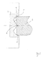
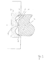
- a displacement of the edge surface of the glazing towards the other protruding outer region of the grinding surface takes place.
- a grinding wheel is used for grinding, the peripheral grinding surface is additionally provided with at least one provided between its two side edges circumferential projection. This is designed so that this comes at least one circumferential projection only after the self-centering of the edge surface of the glazing by the rounded or beveled shape of the outwardly facing projecting portions of the grinding surface with the edge surface.
- the edge surface of the glazing is provided with a shape that is so mirror-symmetrical on the one hand with respect to the edge regions, that both the region of the upper circumferential glass edge and the region of the lower circumferential glass edge in a rounded or chamfered shape respectively with respect to the central region formed in the same manner receding in the direction of the center of the glazing, but on the other hand additionally provided with at least one provided between the upper and the lower edge of the glass peripheral groove, said groove at each point along the peripheral edge surface always at the same position of the edge surface, relative to the center of the edge surface, is arranged.
- the groove is provided in the middle or at a quarter of the width of the edge surface, this is also the case with thickness of the edge surface which fluctuates due to thickness tolerances of the glazing along the entire course of the edge surface.
- the depth of the at least one groove of the edge surface of the glazing is less than the depth of the rounded edge portions and the height of the at least one protrusion of the abrasive surface is less than the height of the rounded edge portions of the abrasive surface.
- the geometric dimensions of the edge surface of the glazing and the geometric dimensions of the grinding surface of the grinding wheel are matched to one another such that the at least one circumferential projection of the grinding wheel only after the self-centering of the edge surface of the glazing by the rounded or beveled shape of the outwardly projecting portions the grinding surface with the edge surface in engagement comes.
- the edge surface of the glazing is centered in relation to the glazing surface of the glazing before the grinding of the at least one groove begins.
- the relatively uniform position of at least one groove is effected based on the width of the edge surface.
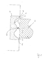
- Fig. 1 shows the first method step of a method for grinding the peripheral edge surface 1 of a glazing 2 by means of a grinding wheel 3.
- the edge surface 1 of the glazing 2 is guided past the grinding wheel 3 and / or the grinding wheel 3 is guided past the edge surface 1 of the glazing 2 ,
- the edge surface 1 in this case has an upper circumferential glass edge 4 and a lower peripheral glass edge 5 in the orientation shown.
- the grinding wheel 3 in turn has a peripheral circumferential grinding surface 6, which is mirror-symmetrical in such a way that the outer regions 7, 8 of the grinding surface 6 in rounded or bevelled shape in each case with respect to the central region of the grinding surface in the same way in the radial outward direction pointing are formed protruding.
- the distance between the outwardly protruding outer regions 7, 8 of the grinding surface is greater than the width of the edge surface 1 of the glazing 2, so that the edge surface 1 for grinding in the region between the above-formed outer regions 7, 8 of the grinding surface 6 is insertable.
- the height of the projection 9 is formed smaller than the height of the rounded or bevelled edge portions 7, 8 of the grinding surface 3, so that the projection 9 only after the self-centering of the edge surface 1 of the glazing 2 by the rounded or beveled shape in the radial Direction outwardly protruding portions 7, 8 of the grinding surface 3 with the edge surface 1 is engaged.
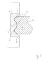
- the desired contour of the edge surface 1 of the glazing 2 results lateral rounding of the glass edges 5, 6 and a depression 10 located between the glass edges 5, 6 includes.
Landscapes
- Engineering & Computer Science (AREA)
- Chemical & Material Sciences (AREA)
- Ceramic Engineering (AREA)
- Inorganic Chemistry (AREA)
- Mechanical Engineering (AREA)
- Grinding And Polishing Of Tertiary Curved Surfaces And Surfaces With Complex Shapes (AREA)
Priority Applications (1)
| Application Number | Priority Date | Filing Date | Title |
|---|---|---|---|
| EP11170781A EP2537634A1 (fr) | 2011-06-21 | 2011-06-21 | Procédé de ponçage de la surface d'angle circonférentielle d'une vitrification |
Applications Claiming Priority (1)
| Application Number | Priority Date | Filing Date | Title |
|---|---|---|---|
| EP11170781A EP2537634A1 (fr) | 2011-06-21 | 2011-06-21 | Procédé de ponçage de la surface d'angle circonférentielle d'une vitrification |
Publications (1)
| Publication Number | Publication Date |
|---|---|
| EP2537634A1 true EP2537634A1 (fr) | 2012-12-26 |
Family
ID=44587654
Family Applications (1)
| Application Number | Title | Priority Date | Filing Date |
|---|---|---|---|
| EP11170781A Withdrawn EP2537634A1 (fr) | 2011-06-21 | 2011-06-21 | Procédé de ponçage de la surface d'angle circonférentielle d'une vitrification |
Country Status (1)
| Country | Link |
|---|---|
| EP (1) | EP2537634A1 (fr) |
Cited By (2)
| Publication number | Priority date | Publication date | Assignee | Title |
|---|---|---|---|---|
| EP3053703A4 (fr) * | 2013-10-04 | 2017-07-26 | Fujimi Incorporated | Dispositif de polissage et procédé de polissage |
| CN110181418A (zh) * | 2019-06-28 | 2019-08-30 | 江苏铁锚玻璃股份有限公司 | 具有渐变化槽口的c型磨轮及其制作方法 |
Citations (4)
| Publication number | Priority date | Publication date | Assignee | Title |
|---|---|---|---|---|
| CH687913A5 (de) * | 1993-11-19 | 1997-03-27 | Bystronic Masch | Bearbeitungsverfahren und Schleifmaschine bzw. Schleifscheibe zur Durchfuehrung desselben. |
| EP0842904A1 (fr) * | 1996-04-11 | 1998-05-20 | Nippon Sheet Glass Co., Ltd. | Vert plat trempe thermiquement et procede de finition des bordures dudit verre |
| US5908675A (en) * | 1995-08-10 | 1999-06-01 | Flachglas Automotive Gmbh | Glass laminate and method of making same |
| US20020054976A1 (en) * | 2000-07-21 | 2002-05-09 | Shoji Nakamura | Molded glass substrate for magnetic disk and method for manufacturing the same |
-
2011
- 2011-06-21 EP EP11170781A patent/EP2537634A1/fr not_active Withdrawn
Patent Citations (4)
| Publication number | Priority date | Publication date | Assignee | Title |
|---|---|---|---|---|
| CH687913A5 (de) * | 1993-11-19 | 1997-03-27 | Bystronic Masch | Bearbeitungsverfahren und Schleifmaschine bzw. Schleifscheibe zur Durchfuehrung desselben. |
| US5908675A (en) * | 1995-08-10 | 1999-06-01 | Flachglas Automotive Gmbh | Glass laminate and method of making same |
| EP0842904A1 (fr) * | 1996-04-11 | 1998-05-20 | Nippon Sheet Glass Co., Ltd. | Vert plat trempe thermiquement et procede de finition des bordures dudit verre |
| US20020054976A1 (en) * | 2000-07-21 | 2002-05-09 | Shoji Nakamura | Molded glass substrate for magnetic disk and method for manufacturing the same |
Cited By (2)
| Publication number | Priority date | Publication date | Assignee | Title |
|---|---|---|---|---|
| EP3053703A4 (fr) * | 2013-10-04 | 2017-07-26 | Fujimi Incorporated | Dispositif de polissage et procédé de polissage |
| CN110181418A (zh) * | 2019-06-28 | 2019-08-30 | 江苏铁锚玻璃股份有限公司 | 具有渐变化槽口的c型磨轮及其制作方法 |
Similar Documents
| Publication | Publication Date | Title |
|---|---|---|
| WO2012035022A1 (fr) | Système de joint périphérique | |
| DE102013105812A1 (de) | Schraubenantrieb | |
| WO2013093900A1 (fr) | Joint de fente en forme de mâchoire ou de griffe | |
| EP2893207B1 (fr) | Cage axiale pour corps de roulement cylindriques | |
| DE10220233A1 (de) | Mutter und Verfahren zu ihrer Herstellung | |
| DE102011010912A1 (de) | Bremsbelaganordnung für eine Scheibenbremse und Verfahren zum Herstellen einer Bremsbelaganordnung | |
| WO2012017094A2 (fr) | Agencement pour étanchéifier une liaison rotative | |
| DE102015220774B4 (de) | Radträger oder Schwenklager eines Fahrzeugs mit einem Radlager | |
| EP2907776B1 (fr) | Dispositif de transport doté d'élément de transport stratiforme sans fin | |
| WO2003083328A1 (fr) | Vis d'entrainement a billes pourvue d'une piece de renvoi | |
| WO2018054416A1 (fr) | Joint d'étanchéité pour palier de roue avec joint de pré-étanchéité intégré | |
| EP2959195B1 (fr) | Procédé de fabrication d'un élément d'étanchéité | |
| DE20209505U1 (de) | Bolzen-Scheiben-Anordnung und deren Elemente | |
| EP2527694B1 (fr) | Joint fendu en forme de griffe ou de mâchoire | |
| EP0441287B1 (fr) | Lame métallique d'insertion pour bandes d'enjolivement et d'étanchéité | |
| WO2012019702A1 (fr) | Brosse à polir | |
| DE102020128146A1 (de) | Dynamische Eingriffsdichtungsvorrichtung und -system mit verbessertem Kontaktverhalten | |
| DE69307813T2 (de) | Querelement für endloses Antriebsorgan | |
| EP4104972B1 (fr) | Outil d'usinage, dispositif d'usinage et procédé d'usinage | |
| DE102016210696B3 (de) | Axialwinkelscheibe | |
| DE102010010487B4 (de) | Käfig für Kugelgelenk und Kugelgelenk | |
| DE102012213033A1 (de) | Verfahren zur Herstellung eines Lagerrings eines Zylinderrollenlagers | |
| DE102014100979B4 (de) | Lagerbuchse | |
| DE102018212054B4 (de) | Bauteilverbund | |
| DE102019122836A1 (de) | Rotorbaugruppe mit einem Endring, der mit gekrümmten Vertiefungen verkerbt ist, und Verfahren zu deren Herstellung |
Legal Events
| Date | Code | Title | Description |
|---|---|---|---|
| PUAI | Public reference made under article 153(3) epc to a published international application that has entered the european phase |
Free format text: ORIGINAL CODE: 0009012 |
|
| AK | Designated contracting states |
Kind code of ref document: A1 Designated state(s): AL AT BE BG CH CY CZ DE DK EE ES FI FR GB GR HR HU IE IS IT LI LT LU LV MC MK MT NL NO PL PT RO RS SE SI SK SM TR |
|
| AX | Request for extension of the european patent |
Extension state: BA ME |
|
| STAA | Information on the status of an ep patent application or granted ep patent |
Free format text: STATUS: THE APPLICATION HAS BEEN WITHDRAWN |
|
| 18W | Application withdrawn |
Effective date: 20130521 |