EP2537737A2 - Vorrichtung zum Anheben von Fahrzeugersatzrädern - Google Patents
Vorrichtung zum Anheben von Fahrzeugersatzrädern Download PDFInfo
- Publication number
- EP2537737A2 EP2537737A2 EP20120382232 EP12382232A EP2537737A2 EP 2537737 A2 EP2537737 A2 EP 2537737A2 EP 20120382232 EP20120382232 EP 20120382232 EP 12382232 A EP12382232 A EP 12382232A EP 2537737 A2 EP2537737 A2 EP 2537737A2
- Authority
- EP
- European Patent Office
- Prior art keywords
- shaft
- rotation
- cam
- safety actuator
- unit according
- Prior art date
- Legal status (The legal status is an assumption and is not a legal conclusion. Google has not performed a legal analysis and makes no representation as to the accuracy of the status listed.)
- Granted
Links
Images

Classifications
-
- B—PERFORMING OPERATIONS; TRANSPORTING
- B62—LAND VEHICLES FOR TRAVELLING OTHERWISE THAN ON RAILS
- B62D—MOTOR VEHICLES; TRAILERS
- B62D43/00—Spare wheel stowing, holding, or mounting arrangements
- B62D43/002—Handling devices, mainly for heavy wheels
-
- B—PERFORMING OPERATIONS; TRANSPORTING
- B62—LAND VEHICLES FOR TRAVELLING OTHERWISE THAN ON RAILS
- B62D—MOTOR VEHICLES; TRAILERS
- B62D43/00—Spare wheel stowing, holding, or mounting arrangements
-
- B—PERFORMING OPERATIONS; TRANSPORTING
- B62—LAND VEHICLES FOR TRAVELLING OTHERWISE THAN ON RAILS
- B62D—MOTOR VEHICLES; TRAILERS
- B62D43/00—Spare wheel stowing, holding, or mounting arrangements
- B62D43/02—Spare wheel stowing, holding, or mounting arrangements external to the vehicle body
- B62D43/04—Spare wheel stowing, holding, or mounting arrangements external to the vehicle body attached beneath the vehicle body
- B62D43/045—Spare wheel stowing, holding, or mounting arrangements external to the vehicle body attached beneath the vehicle body the wheel or its cradle being attached to one or more chains or cables for handling
-
- Y—GENERAL TAGGING OF NEW TECHNOLOGICAL DEVELOPMENTS; GENERAL TAGGING OF CROSS-SECTIONAL TECHNOLOGIES SPANNING OVER SEVERAL SECTIONS OF THE IPC; TECHNICAL SUBJECTS COVERED BY FORMER USPC CROSS-REFERENCE ART COLLECTIONS [XRACs] AND DIGESTS
- Y10—TECHNICAL SUBJECTS COVERED BY FORMER USPC
- Y10T—TECHNICAL SUBJECTS COVERED BY FORMER US CLASSIFICATION
- Y10T74/00—Machine element or mechanism
- Y10T74/18—Mechanical movements
- Y10T74/18056—Rotary to or from reciprocating or oscillating
- Y10T74/18296—Cam and slide
Definitions
- This invention relates to units for picking up spare wheels on vehicles.
- Units of this type comprise a main shaft that extends vertically and passes through a central hole of the wheel, a support in which the wheel is supported and is connected to the main shaft, it being capable of being released in order to make the wheel available, and a cable that is connected at one end to the main shaft and at the other end to a mechanism that is disposed with a shaft of rotation on which the user acts with a tool to pick up or release the wheel.
- Units of this type comprise a safety system that consists of an actuator, usually in the shape of a hook, that closes and acts on the main shaft when the wheel has been disposed against the chassis of the vehicle, and is connected to the mechanism by a connection means, so that when an unwanted effect occurs such as the cable breaking, the main shaft comes away and starts to fall but is supported because the hook of the safety actuator supports it.
- an auxiliary safety mechanism that enables the hook to be released from its action with the main shaft, acting on the mechanism, and the user may release the wheel.
- Document US6092790 A discloses a unit of this type.
- a mechanism for releasing the auxiliary safety device of the spare-wheel-picking up unit in which in order to release the hook of the safety actuator that is acting on the main shaft, the tool that is used to act on the shaft of rotation of the mechanism is used, it being inserted in a pipe that is found in said mechanism in order to access its shaft.
- Inside said pipe there is disposed a cam that interrupts the path of the tool, with the result that as said tool passes to reach the shaft of rotation the cam is rotated, said rotation causing the traction of a cable connected at one end to the cam and at the other end to the hook of the safety actuator, which is released from the main shaft.
- the unit for picking up spare wheels of the invention is designed for its use in vehicles, and more specifically for its use in the picking up (or releasing) of spare wheels of said vehicles.
- Said unit comprises a main shaft extended vertically and which is surrounded by the spare wheel during its picking up.
- the unit also comprises a cable fixed to said main shaft at one end and a mechanism with a shaft of rotation to wind or release the cable and therefore pick up the wheel at the other.
- Said unit also comprises a safety actuator that acts on the main shaft by means of a hook that closes and acts on said shaft when the wheel has been disposed against the chassis of the vehicle, being connected to the mechanism by a connection means, with the result that when an unwanted effect occurs, such as the cable breaking, the main shaft is supported because the hook of the safety actuator supports it.
- the unit also comprises a drive means that is found in the mechanism and connects it to the connection means, with the result that it cooperates with the safety actuator, releasing it, by means of a displacement and rotation movement.
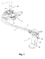
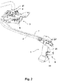
- Figures 1 and 2 show a view in perspective of an embodiment of the unit of the invention, a unit designed for its use in vehicles, and more specifically a unit designed to pick up or release a spare wheel of said vehicle, which is disposed beneath the chassis (or on the underside) of the vehicle.
- Said unit comprises a main shaft 1 that extends vertically and passes through a central hole of the wheel (not shown in the figure), said main shaft 1 comprising a support on which the wheel is supported.
- the unit also comprises a mechanism 3 that enables the winding or releasing of a cable 2 that is connected at one end to said mechanism 3 and at the other to the main shaft 1.
- Said mechanism 3 has a shaft of rotation 4 for performing the action of winding or releasing the cable 2, which has one end 24 that is accessed with a tool 27 for operating the shaft of rotation 4.
- the unit also comprises a safety actuator 5 that acts on the main shaft 1 by means of a hook 25 that closes on the main shaft 1, when the wheel is up against the chassis of the vehicle. When an unwanted effect occurs, for example when the cable 2 breaks, the main shaft 1 comes away but immediately catches against the hook 25 of the safety actuator 5 and the wheel is suspended.
- the hook 25 is closed on the main shaft 1 due to a spring 26 that keeps it in position, and is connected to the mechanism 3 by a connection means 7 such as a cable or towrope, there being in said mechanism 3 a device that enables the hook 25 to be released when the user needs to access the wheel.
- a connection means 7 such as a cable or towrope
- the unit of the invention also comprises a drive means 6, disposed in the mechanism 3, which connects said mechanism 3 and the connection means 7, and cooperates with the safety actuator 5 causing its release in a movement that combines rotation and displacement.
- the drive means 6 is a device that comprises a displacement support 8 and a cam 9.
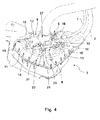
- said drive means 6 In order for said drive means 6 to move and act on the safety actuator 5, it requires additional members that allow it to do so. Said members are found in the mechanism 3, and in the embodiment described specifically on the cover that covers said mechanism 3, which allows access only to the end 24 of the shaft of rotation 4.
- the mechanism 3 comprises in this embodiment of the invention two substantially horizontal guides 10 of the displacement support 8, located on one side of the shaft of rotation 4 on the side where the connection means 7 is accessed and symmetrical in relation to the longitudinal axis of the shaft of rotation 4. It also comprises at least one cam guide 11 located on the other side of the shaft of rotation 4, diametrically opposite the guides 10 of the displacement support 8, and centred on the longitudinal axis of the shaft of rotation 4.
- This cam guide 11 has a shape that, starting from the side of the shaft of rotation 4, gradually moves from a descending shape to a substantially flat central part in order to end in a third part with the shape of an ascending curve.
- the displacement support 8 comprises a central body 12 centred on the longitudinal axis of the shaft of rotation 4, with two side arms 13 that surround said shaft of rotation 4 and are disposed with pivoting connections 14 on their ends. It also comprises a shaft 15 incorporated into the central body 12 in a transverse direction to the longitudinal axis of the displacement support 8, with ends that project out of said support and slide in the guides 10 of the displacement support 8, and comprises a housing 16 disposed in the central body 12, preferably in its centre, in which is housed one end of the connection means 7.
- the cam 9 is located on the side of the shaft of rotation 4 diametrically opposite the location of the connection of the connection means 7 with the displacement support 8, and centred on its axis in the longitudinal axis of the shaft of rotation 4. It comprises an arm 17 with two side levers 18 with a shaft 19 fitted between the ends of said levers 18, said shaft 19 sliding in the cam guide 11, the ends of the shaft 19 being connected in a pivoting manner with the pivoting connections 14 of the side arms 13 of the displacement support 8. It also comprises a second fork-shaped arm 20 with two side arms, which is connected rigidly to the arm 17 in a shaft of rotation 21 forming an angle between both arms 17, 20, preferably between 90 and 180°. In addition the cam 9 also comprises two arms 22 connected in a pivoting manner at one end to the ends of the shaft of rotation 21, and connected in a pivoting manner at the other end in housings 23 of the mechanism 3, on the cover.
- the drive means 6 is in an active position when the safety actuator 5 is acting on the main shaft 1, it being moved and pulled by the connection means 7, which in turn is pulled by the spring 26 of the hook 25 of the safety actuator 5 towards the main shaft 1.
- the second fork-shaped arm 20 of the cam 9 covers the position of the end 24 of the shaft of rotation 4, preventing access to the tool 27 the user uses to act on the end 24 of the shaft of rotation 4 and release the spare wheel.
- the drive means 6 is in a non-active position when it is moved in an opposite direction to the main shaft 1, and in said position the second fork-shaped arm 20 of the cam 9 does not cover the position of the end 24 of the shaft of rotation 4, allowing access to the tool 27 the user uses to act on the end 24 of the shaft of rotation 4 and release the spare wheel.
- the user wishes to act with the tool 27 on the end 24 of the shaft of rotation 4 of the mechanism 3, in order to release the safety actuator 5 and release the spare wheel, they push with said tool 27 on the second arm 20, forcing it to rotate until it no longer covers the position of the end 24 of the shaft of rotation 4. This rotation causes the displacement of the connection means 7, which acts on the spring 26 of the hook 25, releasing the safety actuator 5.
- the passage from an active position to a non-active position of the drive means 6 is achieved by applying with the head of the tool 27 a downwards force, in the direction of the longitudinal axis of the shaft of rotation 4, on the second arm 20 of the cam 9, forcing it to rotate.
- Said rotation causes a lever arm or torque in the cam 9 that increases gradually, as the cam 9 rotates on the shaft of rotation 21, which is displaced simultaneously, as it pivots with the arms 22 on the housings 23, increasing the distance between the shaft of rotation 21 and the point of application of the tool 27.
- the torque applied is greater, as the distance between the point of application of the force and the shaft of rotation 21 of the cam has increased, and the cam 9 continues to slide with the shaft 19 on the cam guide 11, continuing in the third part in an ascending curve of said cam guide 11.
- the cam 9 rotates a lot and is displaced a little, winding a larger amount of cable 2, said movement being enabled by the fact that the torque applied on the cam 9 is greater even when the opposition of the hook 25 of the safety actuator 5 is also greater in this final part of the path, due to the increase in force of the spring 26.
- the cam 9 rotates until it releases the position of the end 24 of the shaft of rotation 4, causing the displacement of the connection means 7 and releasing the safety actuator 5.
- the drive means 6 is a device that must be operated by the tool 27 of the user, on accessing the shaft of rotation 4 of the mechanism 3, in order to thereby act as a release means of the safety actuator 5.
Landscapes
- Engineering & Computer Science (AREA)
- Chemical & Material Sciences (AREA)
- Combustion & Propulsion (AREA)
- Transportation (AREA)
- Mechanical Engineering (AREA)
- Handcart (AREA)
- Lock And Its Accessories (AREA)
- Vehicle Body Suspensions (AREA)
- Vehicle Cleaning, Maintenance, Repair, Refitting, And Outriggers (AREA)
- Mechanical Control Devices (AREA)
- Emergency Lowering Means (AREA)
Applications Claiming Priority (1)
| Application Number | Priority Date | Filing Date | Title |
|---|---|---|---|
| ES201131057A ES2400644B1 (es) | 2011-06-22 | 2011-06-22 | Unidad de recogida de ruedas de repuesto en vehículos |
Publications (3)
| Publication Number | Publication Date |
|---|---|
| EP2537737A2 true EP2537737A2 (de) | 2012-12-26 |
| EP2537737A3 EP2537737A3 (de) | 2014-03-05 |
| EP2537737B1 EP2537737B1 (de) | 2015-06-24 |
Family
ID=46298337
Family Applications (1)
| Application Number | Title | Priority Date | Filing Date |
|---|---|---|---|
| EP12382232.2A Not-in-force EP2537737B1 (de) | 2011-06-22 | 2012-06-06 | Vorrichtung zum Anheben von Fahrzeugersatzrädern |
Country Status (5)
| Country | Link |
|---|---|
| US (1) | US8777071B2 (de) |
| EP (1) | EP2537737B1 (de) |
| CN (1) | CN102837746A (de) |
| BR (1) | BR102012015269A2 (de) |
| ES (1) | ES2400644B1 (de) |
Families Citing this family (1)
| Publication number | Priority date | Publication date | Assignee | Title |
|---|---|---|---|---|
| ES2406856B1 (es) * | 2011-12-06 | 2014-09-02 | Batz, S.Coop. | Unidad de recogida de ruedas de repuesto en vehículos |
Citations (1)
| Publication number | Priority date | Publication date | Assignee | Title |
|---|---|---|---|---|
| US6092790A (en) | 1992-10-06 | 2000-07-25 | Fabricated Steel Products Inc. | Safety latch for a tire carrier and improvements therefor |
Family Cites Families (24)
| Publication number | Priority date | Publication date | Assignee | Title |
|---|---|---|---|---|
| FR1551853A (de) | 1965-12-10 | 1969-01-03 | ||
| GB1185550A (en) | 1967-10-17 | 1970-03-25 | Ford Motor Co | Spare Wheel Carriers |
| US3554415A (en) * | 1968-07-26 | 1971-01-12 | William T Woods | Bumper with spare tire carrier assembly |
| US3865264A (en) * | 1972-10-10 | 1975-02-11 | Caddie Ind Inc | Spare tire mount |
| US4278191A (en) * | 1979-12-10 | 1981-07-14 | Lynn Mecham | Spare tire carrier |
| US4428513A (en) * | 1982-11-26 | 1984-01-31 | General Motors Corporation | Spare wheel carrier |
| US4884785A (en) * | 1988-08-26 | 1989-12-05 | Deuer Manufacturing Inc. | Apparatus for securing a spare tire on a vehicle |
| US4988023A (en) * | 1989-03-21 | 1991-01-29 | Heathcoat Ellis W | Modified spare tire carrier security device |
| US5076629A (en) * | 1990-12-14 | 1991-12-31 | Chrysler Corporation | Spare tire stowage arrangement |
| US5197641A (en) * | 1991-02-19 | 1993-03-30 | L & M Sales, Inc. | Spare tire carrier apparatus |
| DE69221345T2 (de) * | 1991-02-28 | 1997-11-20 | Ford Werke Ag | Seilwinden |
| US5531558A (en) * | 1994-06-22 | 1996-07-02 | Ruescher; Edward H. | Spare tire lifting device |
| US5638711C1 (en) * | 1996-03-28 | 2001-05-15 | Trident Lab Inc | Spare tire locking device |
| US5791859A (en) * | 1997-03-21 | 1998-08-11 | Simnacher; Larry W. | Tire deploying apparatus |
| US5954246A (en) * | 1998-01-20 | 1999-09-21 | Ford Motor Company | Automotive spare tire storage system |
| US6079932A (en) * | 1998-06-22 | 2000-06-27 | Honda Giken Kogyo Kabushiki Kaisha | Corrosion resistant spare tire storage and retrieval system and safety latch assembly for a vehicle, and method of using same |
| US6267546B1 (en) | 1999-03-31 | 2001-07-31 | Dura Global Technologies, Inc. | Secondary latch for a tire carrier |
| IL130974A0 (en) * | 1999-07-15 | 2001-01-28 | Mag Eh Ltd | Load securing device |
| US6561489B1 (en) * | 2000-03-07 | 2003-05-13 | Defs Inc | Automatic winch drive system |
| DE20013754U1 (de) * | 2000-08-10 | 2001-12-13 | Gebr. Dingerkus GmbH & Co. KG, 57439 Attendorn | Kraftfahrzeug mit Seilwinde zum Anheben und Absenken des Reserverades |
| ITTO20030969A1 (it) * | 2003-12-03 | 2005-06-04 | Proma Srl | Unita' di supporto per una ruota di scorta esterna. |
| ITTO20070150U1 (it) | 2007-12-05 | 2009-06-06 | Proma Srl | Unita' di supporto per una ruota di scorta esterna. |
| CN101920727B (zh) * | 2009-06-12 | 2012-11-21 | 本田技研工业株式会社 | 车身后部构造 |
| ES2394661B1 (es) * | 2010-09-15 | 2014-02-28 | Batz, S.Coop. | Dispositivo de seguridad para un sistema de recogida de ruedas de repuesto. |
-
2011
- 2011-06-22 ES ES201131057A patent/ES2400644B1/es not_active Expired - Fee Related
-
2012
- 2012-06-06 EP EP12382232.2A patent/EP2537737B1/de not_active Not-in-force
- 2012-06-20 US US13/528,824 patent/US8777071B2/en active Active
- 2012-06-20 BR BR102012015269-0A patent/BR102012015269A2/pt not_active IP Right Cessation
- 2012-06-20 CN CN2012102099826A patent/CN102837746A/zh active Pending
Patent Citations (1)
| Publication number | Priority date | Publication date | Assignee | Title |
|---|---|---|---|---|
| US6092790A (en) | 1992-10-06 | 2000-07-25 | Fabricated Steel Products Inc. | Safety latch for a tire carrier and improvements therefor |
Also Published As
| Publication number | Publication date |
|---|---|
| ES2400644A2 (es) | 2013-04-11 |
| BR102012015269A2 (pt) | 2014-02-11 |
| US8777071B2 (en) | 2014-07-15 |
| ES2400644R1 (es) | 2013-04-17 |
| CN102837746A (zh) | 2012-12-26 |
| EP2537737A3 (de) | 2014-03-05 |
| US20120325870A1 (en) | 2012-12-27 |
| EP2537737B1 (de) | 2015-06-24 |
| ES2400644B1 (es) | 2014-02-12 |
Similar Documents
| Publication | Publication Date | Title |
|---|---|---|
| US10023223B2 (en) | Steering column assembly | |
| EP2631155A1 (de) | Lenkvorrichtung für ein fahrzeug | |
| EP2301815A1 (de) | Feststellbremsvorrichtung für ein Motorrad | |
| RU2624192C2 (ru) | Устройство проводки функционального тросика | |
| JP5264903B2 (ja) | 自動車のボンネット用のロック装置 | |
| EP2943389B1 (de) | Klemmvorrichtung für eine lenksäulenanordnung | |
| AU2016221792B2 (en) | Pivoting fitting | |
| US20080245176A1 (en) | Steering column assembly having an actuation mechanism for telescoping and tilting movement | |
| EP2537737B1 (de) | Vorrichtung zum Anheben von Fahrzeugersatzrädern | |
| US10137923B2 (en) | Steering column assembly | |
| CN110087973A (zh) | 伸缩范围可调节的转向柱组件 | |
| CN204782397U (zh) | 加油口盖手柄机构及汽车 | |
| US8857851B2 (en) | Restrained shift cable bracket in an adjustable steering column | |
| JP4950905B2 (ja) | ドアーロック機構 | |
| CN108516045A (zh) | 用于自行车的前变速器 | |
| JP2006143196A (ja) | ペダル力低減のための装置 | |
| JP6306490B2 (ja) | 車両用ドアハンドル装置 | |
| EP1669268A1 (de) | Seilspanner für eine Fahrzeug-Handbremse | |
| JP2014213767A (ja) | 可動部材の組み付け構造 | |
| US9180843B2 (en) | Dual rate dual direction spring system | |
| CN202448966U (zh) | 驻车制动机构 | |
| EP3713824B1 (de) | Kombiniertes bremssystem für fahrzeuge, insbesondere für motorräder | |
| EP3810955B1 (de) | Parkvorrichtung eines bremssattels für eine scheibenbremse eines fahrzeugs | |
| EP1810901A2 (de) | Handfeststellbremse für fahrzeuge mit einem absenkhebel | |
| US20160154419A1 (en) | Structure for reducing clutch pedal effort |
Legal Events
| Date | Code | Title | Description |
|---|---|---|---|
| PUAI | Public reference made under article 153(3) epc to a published international application that has entered the european phase |
Free format text: ORIGINAL CODE: 0009012 |
|
| 17P | Request for examination filed |
Effective date: 20120606 |
|
| AK | Designated contracting states |
Kind code of ref document: A2 Designated state(s): AL AT BE BG CH CY CZ DE DK EE ES FI FR GB GR HR HU IE IS IT LI LT LU LV MC MK MT NL NO PL PT RO RS SE SI SK SM TR |
|
| AX | Request for extension of the european patent |
Extension state: BA ME |
|
| PUAL | Search report despatched |
Free format text: ORIGINAL CODE: 0009013 |
|
| AK | Designated contracting states |
Kind code of ref document: A3 Designated state(s): AL AT BE BG CH CY CZ DE DK EE ES FI FR GB GR HR HU IE IS IT LI LT LU LV MC MK MT NL NO PL PT RO RS SE SI SK SM TR |
|
| AX | Request for extension of the european patent |
Extension state: BA ME |
|
| RIC1 | Information provided on ipc code assigned before grant |
Ipc: B62D 43/00 20060101AFI20140129BHEP Ipc: B62D 43/04 20060101ALI20140129BHEP |
|
| RBV | Designated contracting states (corrected) |
Designated state(s): AL AT BE BG CH CY CZ DE DK EE ES FI FR GB GR HR HU IE IS IT LI LT LU LV MC MK MT NL NO PL PT RO RS SE SI SK SM TR |
|
| GRAP | Despatch of communication of intention to grant a patent |
Free format text: ORIGINAL CODE: EPIDOSNIGR1 |
|
| INTG | Intention to grant announced |
Effective date: 20150410 |
|
| GRAS | Grant fee paid |
Free format text: ORIGINAL CODE: EPIDOSNIGR3 |
|
| GRAA | (expected) grant |
Free format text: ORIGINAL CODE: 0009210 |
|
| AK | Designated contracting states |
Kind code of ref document: B1 Designated state(s): AL AT BE BG CH CY CZ DE DK EE ES FI FR GB GR HR HU IE IS IT LI LT LU LV MC MK MT NL NO PL PT RO RS SE SI SK SM TR |
|
| REG | Reference to a national code |
Ref country code: GB Ref legal event code: FG4D |
|
| REG | Reference to a national code |
Ref country code: CH Ref legal event code: EP |
|
| REG | Reference to a national code |
Ref country code: AT Ref legal event code: REF Ref document number: 732755 Country of ref document: AT Kind code of ref document: T Effective date: 20150715 |
|
| REG | Reference to a national code |
Ref country code: IE Ref legal event code: FG4D |
|
| REG | Reference to a national code |
Ref country code: DE Ref legal event code: R096 Ref document number: 602012008193 Country of ref document: DE |
|
| PG25 | Lapsed in a contracting state [announced via postgrant information from national office to epo] |
Ref country code: NO Free format text: LAPSE BECAUSE OF FAILURE TO SUBMIT A TRANSLATION OF THE DESCRIPTION OR TO PAY THE FEE WITHIN THE PRESCRIBED TIME-LIMIT Effective date: 20150924 Ref country code: LT Free format text: LAPSE BECAUSE OF FAILURE TO SUBMIT A TRANSLATION OF THE DESCRIPTION OR TO PAY THE FEE WITHIN THE PRESCRIBED TIME-LIMIT Effective date: 20150624 Ref country code: FI Free format text: LAPSE BECAUSE OF FAILURE TO SUBMIT A TRANSLATION OF THE DESCRIPTION OR TO PAY THE FEE WITHIN THE PRESCRIBED TIME-LIMIT Effective date: 20150624 Ref country code: HR Free format text: LAPSE BECAUSE OF FAILURE TO SUBMIT A TRANSLATION OF THE DESCRIPTION OR TO PAY THE FEE WITHIN THE PRESCRIBED TIME-LIMIT Effective date: 20150624 |
|
| REG | Reference to a national code |
Ref country code: AT Ref legal event code: MK05 Ref document number: 732755 Country of ref document: AT Kind code of ref document: T Effective date: 20150624 |
|
| REG | Reference to a national code |
Ref country code: LT Ref legal event code: MG4D |
|
| PG25 | Lapsed in a contracting state [announced via postgrant information from national office to epo] |
Ref country code: GR Free format text: LAPSE BECAUSE OF FAILURE TO SUBMIT A TRANSLATION OF THE DESCRIPTION OR TO PAY THE FEE WITHIN THE PRESCRIBED TIME-LIMIT Effective date: 20150925 Ref country code: BG Free format text: LAPSE BECAUSE OF FAILURE TO SUBMIT A TRANSLATION OF THE DESCRIPTION OR TO PAY THE FEE WITHIN THE PRESCRIBED TIME-LIMIT Effective date: 20150924 Ref country code: RS Free format text: LAPSE BECAUSE OF FAILURE TO SUBMIT A TRANSLATION OF THE DESCRIPTION OR TO PAY THE FEE WITHIN THE PRESCRIBED TIME-LIMIT Effective date: 20150624 Ref country code: LV Free format text: LAPSE BECAUSE OF FAILURE TO SUBMIT A TRANSLATION OF THE DESCRIPTION OR TO PAY THE FEE WITHIN THE PRESCRIBED TIME-LIMIT Effective date: 20150624 |
|
| REG | Reference to a national code |
Ref country code: NL Ref legal event code: MP Effective date: 20150624 |
|
| PG25 | Lapsed in a contracting state [announced via postgrant information from national office to epo] |
Ref country code: EE Free format text: LAPSE BECAUSE OF FAILURE TO SUBMIT A TRANSLATION OF THE DESCRIPTION OR TO PAY THE FEE WITHIN THE PRESCRIBED TIME-LIMIT Effective date: 20150624 |
|
| PG25 | Lapsed in a contracting state [announced via postgrant information from national office to epo] |
Ref country code: ES Free format text: LAPSE BECAUSE OF FAILURE TO SUBMIT A TRANSLATION OF THE DESCRIPTION OR TO PAY THE FEE WITHIN THE PRESCRIBED TIME-LIMIT Effective date: 20150624 Ref country code: SK Free format text: LAPSE BECAUSE OF FAILURE TO SUBMIT A TRANSLATION OF THE DESCRIPTION OR TO PAY THE FEE WITHIN THE PRESCRIBED TIME-LIMIT Effective date: 20150624 Ref country code: PL Free format text: LAPSE BECAUSE OF FAILURE TO SUBMIT A TRANSLATION OF THE DESCRIPTION OR TO PAY THE FEE WITHIN THE PRESCRIBED TIME-LIMIT Effective date: 20150624 Ref country code: CZ Free format text: LAPSE BECAUSE OF FAILURE TO SUBMIT A TRANSLATION OF THE DESCRIPTION OR TO PAY THE FEE WITHIN THE PRESCRIBED TIME-LIMIT Effective date: 20150624 Ref country code: IS Free format text: LAPSE BECAUSE OF FAILURE TO SUBMIT A TRANSLATION OF THE DESCRIPTION OR TO PAY THE FEE WITHIN THE PRESCRIBED TIME-LIMIT Effective date: 20151024 Ref country code: AT Free format text: LAPSE BECAUSE OF FAILURE TO SUBMIT A TRANSLATION OF THE DESCRIPTION OR TO PAY THE FEE WITHIN THE PRESCRIBED TIME-LIMIT Effective date: 20150624 Ref country code: PT Free format text: LAPSE BECAUSE OF FAILURE TO SUBMIT A TRANSLATION OF THE DESCRIPTION OR TO PAY THE FEE WITHIN THE PRESCRIBED TIME-LIMIT Effective date: 20151026 Ref country code: RO Free format text: LAPSE BECAUSE OF NON-PAYMENT OF DUE FEES Effective date: 20150624 |
|
| REG | Reference to a national code |
Ref country code: DE Ref legal event code: R097 Ref document number: 602012008193 Country of ref document: DE |
|
| PG25 | Lapsed in a contracting state [announced via postgrant information from national office to epo] |
Ref country code: IT Free format text: LAPSE BECAUSE OF FAILURE TO SUBMIT A TRANSLATION OF THE DESCRIPTION OR TO PAY THE FEE WITHIN THE PRESCRIBED TIME-LIMIT Effective date: 20150624 Ref country code: DK Free format text: LAPSE BECAUSE OF FAILURE TO SUBMIT A TRANSLATION OF THE DESCRIPTION OR TO PAY THE FEE WITHIN THE PRESCRIBED TIME-LIMIT Effective date: 20150624 |
|
| PLBE | No opposition filed within time limit |
Free format text: ORIGINAL CODE: 0009261 |
|
| STAA | Information on the status of an ep patent application or granted ep patent |
Free format text: STATUS: NO OPPOSITION FILED WITHIN TIME LIMIT |
|
| 26N | No opposition filed |
Effective date: 20160329 |
|
| PG25 | Lapsed in a contracting state [announced via postgrant information from national office to epo] |
Ref country code: SI Free format text: LAPSE BECAUSE OF FAILURE TO SUBMIT A TRANSLATION OF THE DESCRIPTION OR TO PAY THE FEE WITHIN THE PRESCRIBED TIME-LIMIT Effective date: 20150624 |
|
| PG25 | Lapsed in a contracting state [announced via postgrant information from national office to epo] |
Ref country code: BE Free format text: LAPSE BECAUSE OF FAILURE TO SUBMIT A TRANSLATION OF THE DESCRIPTION OR TO PAY THE FEE WITHIN THE PRESCRIBED TIME-LIMIT Effective date: 20150624 |
|
| PG25 | Lapsed in a contracting state [announced via postgrant information from national office to epo] |
Ref country code: MC Free format text: LAPSE BECAUSE OF FAILURE TO SUBMIT A TRANSLATION OF THE DESCRIPTION OR TO PAY THE FEE WITHIN THE PRESCRIBED TIME-LIMIT Effective date: 20150624 |
|
| REG | Reference to a national code |
Ref country code: CH Ref legal event code: PL |
|
| GBPC | Gb: european patent ceased through non-payment of renewal fee |
Effective date: 20160606 |
|
| REG | Reference to a national code |
Ref country code: IE Ref legal event code: MM4A |
|
| REG | Reference to a national code |
Ref country code: FR Ref legal event code: ST Effective date: 20170228 |
|
| PG25 | Lapsed in a contracting state [announced via postgrant information from national office to epo] |
Ref country code: CH Free format text: LAPSE BECAUSE OF NON-PAYMENT OF DUE FEES Effective date: 20160630 Ref country code: LI Free format text: LAPSE BECAUSE OF NON-PAYMENT OF DUE FEES Effective date: 20160630 Ref country code: FR Free format text: LAPSE BECAUSE OF NON-PAYMENT OF DUE FEES Effective date: 20160630 |
|
| PG25 | Lapsed in a contracting state [announced via postgrant information from national office to epo] |
Ref country code: GB Free format text: LAPSE BECAUSE OF NON-PAYMENT OF DUE FEES Effective date: 20160606 Ref country code: IE Free format text: LAPSE BECAUSE OF NON-PAYMENT OF DUE FEES Effective date: 20160606 |
|
| PG25 | Lapsed in a contracting state [announced via postgrant information from national office to epo] |
Ref country code: NL Free format text: LAPSE BECAUSE OF FAILURE TO SUBMIT A TRANSLATION OF THE DESCRIPTION OR TO PAY THE FEE WITHIN THE PRESCRIBED TIME-LIMIT Effective date: 20150624 Ref country code: SE Free format text: LAPSE BECAUSE OF FAILURE TO SUBMIT A TRANSLATION OF THE DESCRIPTION OR TO PAY THE FEE WITHIN THE PRESCRIBED TIME-LIMIT Effective date: 20150624 |
|
| PG25 | Lapsed in a contracting state [announced via postgrant information from national office to epo] |
Ref country code: CY Free format text: LAPSE BECAUSE OF FAILURE TO SUBMIT A TRANSLATION OF THE DESCRIPTION OR TO PAY THE FEE WITHIN THE PRESCRIBED TIME-LIMIT Effective date: 20150624 Ref country code: HU Free format text: LAPSE BECAUSE OF FAILURE TO SUBMIT A TRANSLATION OF THE DESCRIPTION OR TO PAY THE FEE WITHIN THE PRESCRIBED TIME-LIMIT; INVALID AB INITIO Effective date: 20120606 Ref country code: SM Free format text: LAPSE BECAUSE OF FAILURE TO SUBMIT A TRANSLATION OF THE DESCRIPTION OR TO PAY THE FEE WITHIN THE PRESCRIBED TIME-LIMIT Effective date: 20150624 |
|
| PG25 | Lapsed in a contracting state [announced via postgrant information from national office to epo] |
Ref country code: MT Free format text: LAPSE BECAUSE OF NON-PAYMENT OF DUE FEES Effective date: 20160630 Ref country code: TR Free format text: LAPSE BECAUSE OF FAILURE TO SUBMIT A TRANSLATION OF THE DESCRIPTION OR TO PAY THE FEE WITHIN THE PRESCRIBED TIME-LIMIT Effective date: 20150624 Ref country code: MK Free format text: LAPSE BECAUSE OF FAILURE TO SUBMIT A TRANSLATION OF THE DESCRIPTION OR TO PAY THE FEE WITHIN THE PRESCRIBED TIME-LIMIT Effective date: 20150624 Ref country code: LU Free format text: LAPSE BECAUSE OF NON-PAYMENT OF DUE FEES Effective date: 20160606 |
|
| PG25 | Lapsed in a contracting state [announced via postgrant information from national office to epo] |
Ref country code: AL Free format text: LAPSE BECAUSE OF FAILURE TO SUBMIT A TRANSLATION OF THE DESCRIPTION OR TO PAY THE FEE WITHIN THE PRESCRIBED TIME-LIMIT Effective date: 20150624 |
|
| PGFP | Annual fee paid to national office [announced via postgrant information from national office to epo] |
Ref country code: DE Payment date: 20240627 Year of fee payment: 13 |
|
| REG | Reference to a national code |
Ref country code: DE Ref legal event code: R119 Ref document number: 602012008193 Country of ref document: DE |
|
| PG25 | Lapsed in a contracting state [announced via postgrant information from national office to epo] |
Ref country code: DE Free format text: LAPSE BECAUSE OF NON-PAYMENT OF DUE FEES Effective date: 20260101 |