EP2537991A2 - Profil d'étanchéité pour un système de paroi de séparation, système de paroi de séparation et support de profilé pour un système de paroi de séparation - Google Patents
Profil d'étanchéité pour un système de paroi de séparation, système de paroi de séparation et support de profilé pour un système de paroi de séparation Download PDFInfo
- Publication number
- EP2537991A2 EP2537991A2 EP12173067A EP12173067A EP2537991A2 EP 2537991 A2 EP2537991 A2 EP 2537991A2 EP 12173067 A EP12173067 A EP 12173067A EP 12173067 A EP12173067 A EP 12173067A EP 2537991 A2 EP2537991 A2 EP 2537991A2
- Authority
- EP
- European Patent Office
- Prior art keywords
- sealing
- profile
- partition wall
- wall system
- legs
- Prior art date
- Legal status (The legal status is an assumption and is not a legal conclusion. Google has not performed a legal analysis and makes no representation as to the accuracy of the status listed.)
- Withdrawn
Links
- 238000005192 partition Methods 0.000 title claims abstract description 25
- 238000007789 sealing Methods 0.000 claims description 97
- 210000001503 joint Anatomy 0.000 claims description 11
- 238000011161 development Methods 0.000 description 4
- 230000018109 developmental process Effects 0.000 description 4
- 238000000638 solvent extraction Methods 0.000 description 3
- 239000011521 glass Substances 0.000 description 2
- 239000000463 material Substances 0.000 description 2
- 239000002023 wood Substances 0.000 description 2
- 230000035508 accumulation Effects 0.000 description 1
- 238000009825 accumulation Methods 0.000 description 1
- XAGFODPZIPBFFR-UHFFFAOYSA-N aluminium Chemical compound [Al] XAGFODPZIPBFFR-UHFFFAOYSA-N 0.000 description 1
- 229910052782 aluminium Inorganic materials 0.000 description 1
- 230000015572 biosynthetic process Effects 0.000 description 1
- 230000000295 complement effect Effects 0.000 description 1
- 238000009749 continuous casting Methods 0.000 description 1
- 239000006066 glass batch Substances 0.000 description 1
- 238000003780 insertion Methods 0.000 description 1
- 230000037431 insertion Effects 0.000 description 1
- 238000002955 isolation Methods 0.000 description 1
- 238000000034 method Methods 0.000 description 1
- 239000002985 plastic film Substances 0.000 description 1
- 229920003229 poly(methyl methacrylate) Polymers 0.000 description 1
- 239000004926 polymethyl methacrylate Substances 0.000 description 1
- 239000007787 solid Substances 0.000 description 1
Images

Classifications
-
- E—FIXED CONSTRUCTIONS
- E04—BUILDING
- E04B—GENERAL BUILDING CONSTRUCTIONS; WALLS, e.g. PARTITIONS; ROOFS; FLOORS; CEILINGS; INSULATION OR OTHER PROTECTION OF BUILDINGS
- E04B2/00—Walls, e.g. partitions, for buildings; Wall construction with regard to insulation; Connections specially adapted to walls
- E04B2/74—Removable non-load-bearing partitions; Partitions with a free upper edge
- E04B2/7407—Removable non-load-bearing partitions; Partitions with a free upper edge assembled using frames with infill panels or coverings only; made-up of panels and a support structure incorporating posts
- E04B2/7416—Removable non-load-bearing partitions; Partitions with a free upper edge assembled using frames with infill panels or coverings only; made-up of panels and a support structure incorporating posts with free upper edge, e.g. for use as office space dividers
- E04B2/7433—Removable non-load-bearing partitions; Partitions with a free upper edge assembled using frames with infill panels or coverings only; made-up of panels and a support structure incorporating posts with free upper edge, e.g. for use as office space dividers with panels and support posts
- E04B2/7435—Glazing details
-
- E—FIXED CONSTRUCTIONS
- E04—BUILDING
- E04B—GENERAL BUILDING CONSTRUCTIONS; WALLS, e.g. PARTITIONS; ROOFS; FLOORS; CEILINGS; INSULATION OR OTHER PROTECTION OF BUILDINGS
- E04B1/00—Constructions in general; Structures which are not restricted either to walls, e.g. partitions, or floors or ceilings or roofs
- E04B1/62—Insulation or other protection; Elements or use of specified material therefor
- E04B1/66—Sealings
- E04B1/68—Sealings of joints, e.g. expansion joints
-
- E—FIXED CONSTRUCTIONS
- E04—BUILDING
- E04B—GENERAL BUILDING CONSTRUCTIONS; WALLS, e.g. PARTITIONS; ROOFS; FLOORS; CEILINGS; INSULATION OR OTHER PROTECTION OF BUILDINGS
- E04B2/00—Walls, e.g. partitions, for buildings; Wall construction with regard to insulation; Connections specially adapted to walls
- E04B2/74—Removable non-load-bearing partitions; Partitions with a free upper edge
- E04B2/76—Removable non-load-bearing partitions; Partitions with a free upper edge with framework or posts of metal
- E04B2/78—Removable non-load-bearing partitions; Partitions with a free upper edge with framework or posts of metal characterised by special cross-section of the frame members as far as important for securing wall panels to a framework with or without the help of cover-strips
- E04B2/7809—Removable non-load-bearing partitions; Partitions with a free upper edge with framework or posts of metal characterised by special cross-section of the frame members as far as important for securing wall panels to a framework with or without the help of cover-strips of single or multiple tubular form
- E04B2/7818—Removable non-load-bearing partitions; Partitions with a free upper edge with framework or posts of metal characterised by special cross-section of the frame members as far as important for securing wall panels to a framework with or without the help of cover-strips of single or multiple tubular form of substantially rectangular form
- E04B2/7836—Removable non-load-bearing partitions; Partitions with a free upper edge with framework or posts of metal characterised by special cross-section of the frame members as far as important for securing wall panels to a framework with or without the help of cover-strips of single or multiple tubular form of substantially rectangular form with only two sides of the profiles having substantially similar undercut grooves or connecting projections
Definitions
- the invention relates to a sealing profile for a partition wall system, a partition wall system and a profile stand for a partition wall system.
- Partition wall systems are for example from the DE 20 2008 016 693 U1 known. That from the DE 20 2008 016 693 U1 known partition wall system comprises supports, so-called profile stand, and plates which are flush mounted by at least one clamping means on an end face of a profile stand.
- the panels are referred to as panels in the context of the present application. These are, for example, glass plates, acrylic glass plates, plates from a glass batch or the like, wood panels made of solid wood or veneer or plastic sheets.
- the panels are preferably arranged in two parallel rows on both sides of the profile stand, wherein panels of a row are separated from each other by a butt joint and in the region of Butt joint are releasably secured to a profile stand.
- a substantially T-shaped clamping means is provided which can be inserted into a groove provided on the end face of the profile stand and groove in the groove.
- sealing strips are arranged with a substantially O-shaped, elastically deformable region.
- a sealing profile for a partition wall system with a substantially U-shaped base body with two legs, wherein at the ends of the legs in each case an elastically deformable sealing segment is arranged projecting outwardly.
- Such a sealing profile can be easily mounted by insertion into an associated groove, wherein the two sealing segments act as contact surfaces for two, separated by a butt joint panels.
- An elastic deformability is suitably defined due to a selected material and / or a design of the sealing segment.
- the sealing profile can be produced as so-called yard goods and can be tailored to a suitable length depending on the application.
- a distance of the legs of the sealing profile corresponds approximately to a width of the butt joint of the panels. The width of the butt joint can be chosen very small in order to create an aesthetically pleasing surface.
- the base body and the sealing segments are produced separately and connectable in a pre-assembly.
- the sealing segments are designed in one piece with the base body.
- the sealing profile is preferably designed symmetrically, so that the two sealing segments are formed in mirror image.
- embodiments are also conceivable in which the two sealing segments are designed differently.
- At least one sealing segment is designed sickle-shaped or annular.
- a sickle-shaped or annular is thereby referred to a tubular closed or interrupted structure whose outer contour has a convexly curved kink-free course.
- At least one sealing segment is U-shaped with a first, adjacent to one of the legs of the body sealing segment leg, a sealing segment base and a second sealing segment leg is designed.
- the first sealing segment leg preferably projects outwardly at right angles or at right angles from the leg of the main body.
- the U-shaped sealing segment is arranged so that the sealing segment base is arranged in alignment with the associated leg of the base body.
- the sealing segment base extends substantially parallel or parallel spaced from the leg of the body. This can be sealing profiles with different height of the sealing segment base for attachment be provided by panels of different thickness or wall thickness.
- the second sealing segment leg is convexly curved.
- the convex curvature allows secure contacting regardless of a degree of deformation of the sealing segment leg.
- the second sealing segment leg is formed with a lower wall thickness than the sealing segment base and / or the first sealing segment leg, so that a deformation takes place predominantly in the region of the second sealing segment leg.
- At least one of the legs of the main body has an engagement nose on an outer side.
- the latch cooperates with a complementary latching area on the profile stand for easy attachment.
- a partition wall system comprising at least one row of two or more each separated by a butt joint panels, which are each releasably secured in the region of the butt joint on a profile stand, wherein the profile stand on at least one, the panels facing end face a groove in which a sealing profile is inserted with outwardly projecting sealing segments, wherein the sealing segments form a contact surface for the panels.
- the groove of the profile stand on an undercut.
- an undercut is a region which has a widened diameter in relation to an opening diameter.
- the locking lugs of the sealing profile act in advantageous embodiments for a clamping attachment with the backgrounds together, the locking lugs engage behind the undercut, thus preventing removal of the sealing profile from the groove.
- the groove of the profile stand is designed as a C-shaped or G-shaped channel.
- a C-shaped structure is referred to as having a U-shaped base portion with a base and two legs, with the free ends of the legs, i. the ends of the legs facing away from the base, a section projecting in the direction of the interior, preferably projecting at right angles, adjoins.
- a structure is referred to, which has a U-shaped base portion with a base and two legs, wherein at the free ends of the legs a rotated by 180 °, projecting towards the interior U-shaped portion , connects.
- the protruding from the legs sections each form an undercut for the sealing profile.
- a clamping strip for fixing the panels to the profile stand between the legs of the main body of the sealing profile can be used.
- the terminal block the panels are fixed, preferably the sealing segments are elastically deformed, so that a clamping of the panels is effected due to the restoring forces.
- a length of the terminal strip is at least substantially equal to a length of the sealing profile, so that the sealing profile is covered over the entire length.
- a plurality of spaced apart short terminal strips are provided. Such terminal strips are particularly advantageous in terms of handling in the assembly.
- the terminal block is formed in advantageous embodiments T-shaped with a base web and substantially parallel or parallel to the panels extending clamping arms.
- the base web of the T-shaped terminal strip is U-shaped.
- a further fixation for example by means of screw, possible.
- screw grooves are provided in one embodiment in a groove bottom of the groove of the profile stand and at a base of the U-shaped base web.
- the object is further achieved by a profile stand for a partition wall system with a groove for receiving a sealing profile.
- the groove is preferably designed as a C-shaped or G-shaped channel.
- the profile stand is formed, for example, as an aluminum profile. Such a profile stand can be produced by continuous casting process in a simple manner.
- Fig. 1 shows a sectional view of a partition wall system 1 with a profile stand 2 and two parallel rows 3a, 3b of each separated by a butt joint panels 30a, 30b.
- the panels 30a, 30b are designed as glass plates. In this case, the panels 30a, 30b of the two rows 3a and 3b have a different wall thickness.
- the panels 30a, 30b are arranged on end faces 20 of the profile stand 2, wherein between the panels 30a, 30b and the profile stand 2 each have a sealing profile 4, 5 is arranged.
- the partition wall system 1 further comprises terminal strips 6, by means of which the panels 30a, 30b are fixed to the profile stand 2.
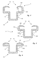
- the sealing profiles 4, 5 are in the Fig. 2 or 3 shown in isolation.
- Fig. 4 shows a further embodiment of a sealing profile 7.
- the sealing profiles 4, 5, 7 each have a substantially U-shaped base body 40, 50, 70 with two legs 41, 51, 71 on. At the ends of the legs 41, 51, 71 in each case an elastically deformable, hook-shaped sealing segment 42, 52, 72 is provided.
- the sealing profiles 4, 5 and 7 are each formed mirror-symmetrically.
- the illustrated sealing segments 42, 52, 72 are each substantially U-shaped with a first, on a leg 41, 51, 71 of the respective base body 40, 50 and 70 adjacent sealing segment leg 420, 520, 720, a sealing segment base 421, 521, 721 and a second sealing segment leg 422, 522, 722.
- the three sealing profiles 4, 5, 7 differ in a height of the respective sealing segment base 421, 521, 721. As in Fig. 1 can be seen, so by the different sealing profiles 4, 5, 7 panels 30a, 30b of different wall thickness can be clamped without additional adjustment.
- the sealing segments 42, 52, 72 are arranged on the respective legs 41, 51, 71 respectively projecting outwardly.
- a length of the two sealing segment legs 420, 422; 520, 522 and 720, 722 are each selected to be substantially equal in length, so that a free end of the sealing segment legs 422, 522, 722 is substantially flush with the interior defined by the legs 41, 51 and 71, respectively.
- a length of the two sealing segment legs 420, 422; 520, 522 and 720, 722 shorter.
- the first sealing segment leg 420, 520, 720 protrudes in the illustrated embodiment at right angles from the associated leg 41, 51, 71 of the base body 40, 50, 70 from. As in Fig. 1 can be seen, so a simple positioning of the sealing profile 4, 5 on the profile stand 2 allows.
- the second sealing segment legs 422, 522, 722, however, are convexly curved.
- the sealing segments 42, 52 are elastically deformed. Due to the convex curvature of the sealing segment legs 422, 522, 722 a secure contacting of the panels 30a, 30b is effected for a secure seal.
- the legs 41, 51, 71 have - as in Fig. 1 illustrated - further locking lugs 410, 510, 710.
- the locking lugs 410, 510, 710 cooperate with an undercut 22 of the profile stand 2 for a latching connection.
- a groove with an undercut 22 is created, which cooperates with the locking lugs 410, 510, 710 for a clamping connection.
- an additional contact surface for the sealing profile 4, 5 and the clamping strips 6 is created in the region of an opening, further material accumulations in the formation of the undercut 22 are avoided.
- the terminal strips 6 are each T-shaped with clamping arms 61 extending parallel to the panels 30a, 30b.
- a base web of the terminal strips 6 U-shaped with two legs 62 designed.
- a screwing of the terminal strips 6 with the profile stand 2 is possible between the legs 62.
- the screw is concealed in some embodiments of a cover profile, not shown, or a piping.
Landscapes
- Engineering & Computer Science (AREA)
- Architecture (AREA)
- Physics & Mathematics (AREA)
- Electromagnetism (AREA)
- Civil Engineering (AREA)
- Structural Engineering (AREA)
- Building Environments (AREA)
- Finishing Walls (AREA)
Applications Claiming Priority (1)
| Application Number | Priority Date | Filing Date | Title |
|---|---|---|---|
| DE202011102338U DE202011102338U1 (de) | 2011-06-22 | 2011-06-22 | Dichtungsprofil für ein Trennwandsystem, Trennwandsystem und Profilständer für ein Trennwandsystem |
Publications (2)
| Publication Number | Publication Date |
|---|---|
| EP2537991A2 true EP2537991A2 (fr) | 2012-12-26 |
| EP2537991A3 EP2537991A3 (fr) | 2016-10-12 |
Family
ID=44508282
Family Applications (1)
| Application Number | Title | Priority Date | Filing Date |
|---|---|---|---|
| EP12173067.5A Withdrawn EP2537991A3 (fr) | 2011-06-22 | 2012-06-21 | Profil d'étanchéité pour un système de paroi de séparation, système de paroi de séparation et support de profilé pour un système de paroi de séparation |
Country Status (2)
| Country | Link |
|---|---|
| EP (1) | EP2537991A3 (fr) |
| DE (1) | DE202011102338U1 (fr) |
Cited By (1)
| Publication number | Priority date | Publication date | Assignee | Title |
|---|---|---|---|---|
| GB2547026A (en) * | 2016-02-05 | 2017-08-09 | Bd Fire And Blast Ltd | A blast-retaining panel wall and connectors therefor |
Families Citing this family (1)
| Publication number | Priority date | Publication date | Assignee | Title |
|---|---|---|---|---|
| FI10235U1 (fi) * | 2012-06-19 | 2013-09-25 | Alutec Oy | Tiivistysjärjestely lasitettavaa parveketta varten |
Citations (2)
| Publication number | Priority date | Publication date | Assignee | Title |
|---|---|---|---|---|
| FR2218447A1 (fr) * | 1973-02-21 | 1974-09-13 | Tondeur Jean Pierre | |
| DE202008016693U1 (de) | 2008-12-09 | 2009-03-26 | Strähle, Werner | Trennwandsystem, sowie Teile hierfür |
Family Cites Families (7)
| Publication number | Priority date | Publication date | Assignee | Title |
|---|---|---|---|---|
| US3623290A (en) * | 1969-07-25 | 1971-11-30 | Lucien R Downing Jr | Partition wall |
| FR2484501A1 (fr) * | 1980-06-13 | 1981-12-18 | Michelet Marceau | Cloisons amovibles a double panneaux et elements pour leur realisation |
| IT8721984A0 (it) * | 1987-09-22 | 1987-09-22 | Coopsette Scrl | Parete divisoria interna componibile a contenitore. |
| DE8810675U1 (de) * | 1988-08-24 | 1988-11-24 | Plan Objekt GmbH & Co, 6082 Mörfelden-Walldorf | Dichtungsprofil für Trennwandsysteme |
| AUPO291296A0 (en) * | 1996-10-11 | 1996-11-07 | Rudduck, Dickory | Building elements |
| DE19945493A1 (de) * | 1998-09-23 | 2000-03-30 | Intek Ges Fuer Moderne Innenba | Innentrennwandeinrichtung |
| DE102005048155A1 (de) * | 2005-10-06 | 2007-04-19 | Dorma Gmbh + Co. Kg | Mobile Trennwand |
-
2011
- 2011-06-22 DE DE202011102338U patent/DE202011102338U1/de not_active Expired - Lifetime
-
2012
- 2012-06-21 EP EP12173067.5A patent/EP2537991A3/fr not_active Withdrawn
Patent Citations (2)
| Publication number | Priority date | Publication date | Assignee | Title |
|---|---|---|---|---|
| FR2218447A1 (fr) * | 1973-02-21 | 1974-09-13 | Tondeur Jean Pierre | |
| DE202008016693U1 (de) | 2008-12-09 | 2009-03-26 | Strähle, Werner | Trennwandsystem, sowie Teile hierfür |
Cited By (1)
| Publication number | Priority date | Publication date | Assignee | Title |
|---|---|---|---|---|
| GB2547026A (en) * | 2016-02-05 | 2017-08-09 | Bd Fire And Blast Ltd | A blast-retaining panel wall and connectors therefor |
Also Published As
| Publication number | Publication date |
|---|---|
| DE202011102338U1 (de) | 2011-07-27 |
| EP2537991A3 (fr) | 2016-10-12 |
Similar Documents
| Publication | Publication Date | Title |
|---|---|---|
| EP2029946B2 (fr) | Système de montage, en particulier pour modules solaires | |
| EP0501994A1 (fr) | Piece moulee pour le raccordement de profiles de construction. | |
| DE202015106983U1 (de) | System zur schraubenlosen Fixierung einer Glasscheibe | |
| EP2754805B1 (fr) | Tringle de verrouillage pour une crémone | |
| EP1138864B1 (fr) | Profilé composite pour fenêtres, façades, portes ou toiture vitrée | |
| EP2754803A2 (fr) | Crémone de fenêtre ou de porte | |
| EP0468446B1 (fr) | Construction de façade constituée de montants et de traverses pour la fixation d'éléments plats | |
| DE7908753U1 (de) | Rahmenprofil fuer ein fenster, eine tuer o.dgl. | |
| DE202011102338U1 (de) | Dichtungsprofil für ein Trennwandsystem, Trennwandsystem und Profilständer für ein Trennwandsystem | |
| DE202013105102U1 (de) | Rahmenprofil für ein Fenster oder eine Tür | |
| EP0104340A2 (fr) | Agencement, en particulier pour une cloison de douche | |
| DE29501568U1 (de) | Verbindungselement | |
| EP0470603A1 (fr) | Dispositif d'étanchéité pour cadre de porte ou fenêtre | |
| DE69710059T2 (de) | Verbindung für ein fenstersystem | |
| EP2418335A2 (fr) | Système d'arrangement variable d'une façade vitrée et un procédé de réalisatiom d'une façade vitrée | |
| DE202012002574U1 (de) | Pfostenverbinder | |
| AT8075U1 (de) | Abschlussleiste | |
| DE102016104405A1 (de) | Verfahren zur Montage einer Pfosten-Riegel-Konstruktion und Montagehilfe | |
| EP1720146B1 (fr) | Dispositif d'affichage d'images | |
| DE102011011055B4 (de) | Dichtung für Pfosten-Riegel-Fassaden | |
| DE202006004607U1 (de) | Rahmenkonstruktion für ein aus Rahmenholmen zusammengesetztes Bauelement | |
| AT517004B1 (de) | Dichtleistengehäuse eines Türdichtungssystems | |
| EP2428633A2 (fr) | Profilé de dormant pour construction de portes, fenêtres ou façades | |
| EP2657444B1 (fr) | Cadre de profilé, en particulier dormant | |
| EP2639909B1 (fr) | Système de caniveaux de câbles |
Legal Events
| Date | Code | Title | Description |
|---|---|---|---|
| PUAI | Public reference made under article 153(3) epc to a published international application that has entered the european phase |
Free format text: ORIGINAL CODE: 0009012 |
|
| AK | Designated contracting states |
Kind code of ref document: A2 Designated state(s): AL AT BE BG CH CY CZ DE DK EE ES FI FR GB GR HR HU IE IS IT LI LT LU LV MC MK MT NL NO PL PT RO RS SE SI SK SM TR |
|
| AX | Request for extension of the european patent |
Extension state: BA ME |
|
| PUAL | Search report despatched |
Free format text: ORIGINAL CODE: 0009013 |
|
| AK | Designated contracting states |
Kind code of ref document: A3 Designated state(s): AL AT BE BG CH CY CZ DE DK EE ES FI FR GB GR HR HU IE IS IT LI LT LU LV MC MK MT NL NO PL PT RO RS SE SI SK SM TR |
|
| AX | Request for extension of the european patent |
Extension state: BA ME |
|
| RIC1 | Information provided on ipc code assigned before grant |
Ipc: E04B 1/68 20060101AFI20160905BHEP |
|
| 17P | Request for examination filed |
Effective date: 20170412 |
|
| RBV | Designated contracting states (corrected) |
Designated state(s): AL AT BE BG CH CY CZ DE DK EE ES FI FR GB GR HR HU IE IS IT LI LT LU LV MC MK MT NL NO PL PT RO RS SE SI SK SM TR |
|
| 17Q | First examination report despatched |
Effective date: 20170630 |
|
| GRAP | Despatch of communication of intention to grant a patent |
Free format text: ORIGINAL CODE: EPIDOSNIGR1 |
|
| INTG | Intention to grant announced |
Effective date: 20171208 |
|
| STAA | Information on the status of an ep patent application or granted ep patent |
Free format text: STATUS: THE APPLICATION IS DEEMED TO BE WITHDRAWN |
|
| 18D | Application deemed to be withdrawn |
Effective date: 20180419 |