EP2538070A2 - Turbine avec rotor a entree et sortie radiales trouvant une application dans des ecoulements bidirectionnels - Google Patents
Turbine avec rotor a entree et sortie radiales trouvant une application dans des ecoulements bidirectionnels Download PDFInfo
- Publication number
- EP2538070A2 EP2538070A2 EP11710901A EP11710901A EP2538070A2 EP 2538070 A2 EP2538070 A2 EP 2538070A2 EP 11710901 A EP11710901 A EP 11710901A EP 11710901 A EP11710901 A EP 11710901A EP 2538070 A2 EP2538070 A2 EP 2538070A2
- Authority
- EP
- European Patent Office
- Prior art keywords
- rotor
- guide vanes
- flow
- turbine
- stator
- Prior art date
- Legal status (The legal status is an assumption and is not a legal conclusion. Google has not performed a legal analysis and makes no representation as to the accuracy of the status listed.)
- Granted
Links
Images
Classifications
-
- F—MECHANICAL ENGINEERING; LIGHTING; HEATING; WEAPONS; BLASTING
- F03—MACHINES OR ENGINES FOR LIQUIDS; WIND, SPRING, OR WEIGHT MOTORS; PRODUCING MECHANICAL POWER OR A REACTIVE PROPULSIVE THRUST, NOT OTHERWISE PROVIDED FOR
- F03B—MACHINES OR ENGINES FOR LIQUIDS
- F03B3/00—Machines or engines of reaction type; Parts or details peculiar thereto
- F03B3/12—Blades; Blade-carrying rotors
-
- F—MECHANICAL ENGINEERING; LIGHTING; HEATING; WEAPONS; BLASTING
- F03—MACHINES OR ENGINES FOR LIQUIDS; WIND, SPRING, OR WEIGHT MOTORS; PRODUCING MECHANICAL POWER OR A REACTIVE PROPULSIVE THRUST, NOT OTHERWISE PROVIDED FOR
- F03B—MACHINES OR ENGINES FOR LIQUIDS
- F03B13/00—Adaptations of machines or engines for special use; Combinations of machines or engines with driving or driven apparatus; Power stations or aggregates
- F03B13/12—Adaptations of machines or engines for special use; Combinations of machines or engines with driving or driven apparatus; Power stations or aggregates characterised by using wave or tide energy
- F03B13/14—Adaptations of machines or engines for special use; Combinations of machines or engines with driving or driven apparatus; Power stations or aggregates characterised by using wave or tide energy using wave energy
- F03B13/16—Adaptations of machines or engines for special use; Combinations of machines or engines with driving or driven apparatus; Power stations or aggregates characterised by using wave or tide energy using wave energy using the relative movement between a wave-operated member, i.e. a "wom" and another member, i.e. a reaction member or "rem"
- F03B13/18—Adaptations of machines or engines for special use; Combinations of machines or engines with driving or driven apparatus; Power stations or aggregates characterised by using wave or tide energy using wave energy using the relative movement between a wave-operated member, i.e. a "wom" and another member, i.e. a reaction member or "rem" where the other member, i.e. rem is fixed, at least at one point, with respect to the sea bed or shore
-
- F—MECHANICAL ENGINEERING; LIGHTING; HEATING; WEAPONS; BLASTING
- F03—MACHINES OR ENGINES FOR LIQUIDS; WIND, SPRING, OR WEIGHT MOTORS; PRODUCING MECHANICAL POWER OR A REACTIVE PROPULSIVE THRUST, NOT OTHERWISE PROVIDED FOR
- F03B—MACHINES OR ENGINES FOR LIQUIDS
- F03B13/00—Adaptations of machines or engines for special use; Combinations of machines or engines with driving or driven apparatus; Power stations or aggregates
- F03B13/12—Adaptations of machines or engines for special use; Combinations of machines or engines with driving or driven apparatus; Power stations or aggregates characterised by using wave or tide energy
- F03B13/14—Adaptations of machines or engines for special use; Combinations of machines or engines with driving or driven apparatus; Power stations or aggregates characterised by using wave or tide energy using wave energy
- F03B13/141—Adaptations of machines or engines for special use; Combinations of machines or engines with driving or driven apparatus; Power stations or aggregates characterised by using wave or tide energy using wave energy with a static energy collector
- F03B13/142—Adaptations of machines or engines for special use; Combinations of machines or engines with driving or driven apparatus; Power stations or aggregates characterised by using wave or tide energy using wave energy with a static energy collector which creates an oscillating water column
-
- F—MECHANICAL ENGINEERING; LIGHTING; HEATING; WEAPONS; BLASTING
- F03—MACHINES OR ENGINES FOR LIQUIDS; WIND, SPRING, OR WEIGHT MOTORS; PRODUCING MECHANICAL POWER OR A REACTIVE PROPULSIVE THRUST, NOT OTHERWISE PROVIDED FOR
- F03B—MACHINES OR ENGINES FOR LIQUIDS
- F03B13/00—Adaptations of machines or engines for special use; Combinations of machines or engines with driving or driven apparatus; Power stations or aggregates
- F03B13/12—Adaptations of machines or engines for special use; Combinations of machines or engines with driving or driven apparatus; Power stations or aggregates characterised by using wave or tide energy
- F03B13/14—Adaptations of machines or engines for special use; Combinations of machines or engines with driving or driven apparatus; Power stations or aggregates characterised by using wave or tide energy using wave energy
- F03B13/22—Adaptations of machines or engines for special use; Combinations of machines or engines with driving or driven apparatus; Power stations or aggregates characterised by using wave or tide energy using wave energy using the flow of water resulting from wave movements to drive a motor or turbine
-
- F—MECHANICAL ENGINEERING; LIGHTING; HEATING; WEAPONS; BLASTING
- F03—MACHINES OR ENGINES FOR LIQUIDS; WIND, SPRING, OR WEIGHT MOTORS; PRODUCING MECHANICAL POWER OR A REACTIVE PROPULSIVE THRUST, NOT OTHERWISE PROVIDED FOR
- F03B—MACHINES OR ENGINES FOR LIQUIDS
- F03B3/00—Machines or engines of reaction type; Parts or details peculiar thereto
- F03B3/16—Stators
- F03B3/18—Stator blades; Guide conduits or vanes, e.g. adjustable
-
- F—MECHANICAL ENGINEERING; LIGHTING; HEATING; WEAPONS; BLASTING
- F05—INDEXING SCHEMES RELATING TO ENGINES OR PUMPS IN VARIOUS SUBCLASSES OF CLASSES F01-F04
- F05B—INDEXING SCHEME RELATING TO WIND, SPRING, WEIGHT, INERTIA OR LIKE MOTORS, TO MACHINES OR ENGINES FOR LIQUIDS COVERED BY SUBCLASSES F03B, F03D AND F03G
- F05B2210/00—Working fluid
- F05B2210/40—Flow geometry or direction
- F05B2210/404—Flow geometry or direction bidirectional, i.e. in opposite, alternating directions
-
- Y—GENERAL TAGGING OF NEW TECHNOLOGICAL DEVELOPMENTS; GENERAL TAGGING OF CROSS-SECTIONAL TECHNOLOGIES SPANNING OVER SEVERAL SECTIONS OF THE IPC; TECHNICAL SUBJECTS COVERED BY FORMER USPC CROSS-REFERENCE ART COLLECTIONS [XRACs] AND DIGESTS
- Y02—TECHNOLOGIES OR APPLICATIONS FOR MITIGATION OR ADAPTATION AGAINST CLIMATE CHANGE
- Y02E—REDUCTION OF GREENHOUSE GAS [GHG] EMISSIONS, RELATED TO ENERGY GENERATION, TRANSMISSION OR DISTRIBUTION
- Y02E10/00—Energy generation through renewable energy sources
- Y02E10/20—Hydro energy
-
- Y—GENERAL TAGGING OF NEW TECHNOLOGICAL DEVELOPMENTS; GENERAL TAGGING OF CROSS-SECTIONAL TECHNOLOGIES SPANNING OVER SEVERAL SECTIONS OF THE IPC; TECHNICAL SUBJECTS COVERED BY FORMER USPC CROSS-REFERENCE ART COLLECTIONS [XRACs] AND DIGESTS
- Y02—TECHNOLOGIES OR APPLICATIONS FOR MITIGATION OR ADAPTATION AGAINST CLIMATE CHANGE
- Y02E—REDUCTION OF GREENHOUSE GAS [GHG] EMISSIONS, RELATED TO ENERGY GENERATION, TRANSMISSION OR DISTRIBUTION
- Y02E10/00—Energy generation through renewable energy sources
- Y02E10/30—Energy from the sea, e.g. using wave energy or salinity gradient
Definitions
- the present invention relates to a turbine which can absorb energy from bi-directional reversing flows, as is the case of ocean wave energy converters.
- An important class of such systems is characterized by the existence of a fixed or oscillating chamber open to the sea at its submerged part. Due to wave action, the water inside the structure is forced into motion. The resulting reciprocating relative motion and the associated forces may be converted into useful energy by means of a turbine.
- a turbine In some systems, known as oscillating water columns, there is an air-water interface at the top of the water column whose reciprocating motion alternately produces a compression and decompression of air which makes an air turbine to move.
- the energy conversion can be made by a hydraulic turbine inside the water column or close to one of its ends. The (air or water) turbine drives (directly or indirectly) an electrical generator if the object is the production of electrical energy.
- the turbine Due to the wavy nature of the sea surface motion, the turbine is required to absorb energy from a bi-directional flow, and so it must be self-rectifying, unless the device is equipped with a rectifying system made up of non-return valves, which has been found unpractical and costly.
- Self-rectifying air turbines have been proposed and used in bi-directional flows for wave energy conversion.
- the Wells turbine is possibly the best known and most frequently used in bi-directional air flows. It is an axial-flow turbine. Its peak efficiency under stationary flow conditions may exceed 70%. However the range of flow rates within which the Wells turbine is capable of operating efficiently is relatively narrow, which results in modest time-averaged efficiencies under real irregular wave conditions.
- the Wells turbine is characterized by relatively large rotational speed and small torque, and also (because it is a reaction turbine) by a large axial force on its rotor. These characteristics may be inconvenient in wave energy applications.
- the self-rectifying axial-flow impulse turbine is possibly the most frequently proposed alternative to the Wells turbine for wave energy applications.
- the axial-flow impulse turbine has been used since the final years of the nineteenth century as a steam turbine (the De Laval steam turbine).
- the fluid is accelerated and circumferentially deflected in a row of nozzles, and then is admitted into a rotor provided with blades. Here it is again deflected, its exit velocity being approximately in the axial direction.
- the rotor blades are shaped in such a way that the rotor inlet pressure is approximately equal to the exit pressure (which characterizes an impulse turbine).
- the turbine should perform in the same way when the incoming flow direction is reversed.
- This problem may be (at least partially) overcome if the setting angle of the guide vanes, or the vane geometry, is adjustable, and is changed whenever the direction of the flow through the turbine is reversed.
- the practical implementation of this kind of control requires the turbine to be equipped with mechanisms that increase the construction and maintenance costs and reduce the reliability of the machine. This has hindered the use of guide vane control.
- An alternative method of reducing the aerodynamic (or hydrodynamic) losses by excessive incidence angle at the entrance to the second row of guide vanes consists in increasing the distance between the guide vane rows and the rotor blades, with the object of reducing the velocity (and hence the kinetic energy) of the flow at the entrance to the second row of guide vanes and in this way reduce the energy losses due to boundary layer separation (stalling) at those vanes.
- the present invention relates to a self-rectifying turbine consisting of a bladed rotor and two rows of guide vanes.
- the flow entrance to, and exit from, the rotor is radial, which means that the axial component of the inlet and outlet flow velocity component is relatively small.
- the inflow to the rotor is centripetal (i.e. in the direction of decreasing radial coordinate), and the outlet flow is centrifugal (i.e. in the direction of increasing radial coordinate).
- the stator has two rows of guide vanes circumferentially located around the rotor, but not axially offset from it as in Patent WO 2008/0112530 .
- the flow between each of the openings in the rotor periphery and the corresponding row of guide vanes is essentially radial (the axial flow velocity is relatively small).
- the connection is provided by a duct formed by two walls of revolution about the rotational axis. One or both such walls may be shaped as flat discs perpendicular to the rotational axis.
- the turbine made up of rotor and stator, has a compact configuration, especially on what concerns its axial extent.
- a flywheel possibly of larger diameter than the turbine rotor itself, may be mounted on the same shaft as, and in the proximity of, the turbine rotor, which allows the shaft torque oscillations to be smoothed out.
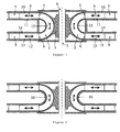
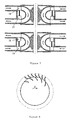
- FIG. 1 Schematic representation of a cross section of the turbine by a plane containing the axis of rotation (1).
- the rotor blades (2) and the guide vanes (7, 8) are circumferentially projected onto the plane of the figure.
- the rotor comprises a set of blades (2) fixed to a hub (3) mounted on a shaft (4).
- the admission of fluid into, and exit from, the rotor takes place at (5) and (6), or vice-versa, depending on the direction of the reversing bi-directional flow through the turbine.
- the stator comprehends two rows of guide vanes (7) and (8), circumferentially disposed around the rotor, located in the radial alignment of the respective rotor openings (5) and (6).
- connection between guide vane row (7) and rotor opening (5) is provided by a duct (9) with walls of revolution (10) and (11).
- One of these walls, or both, may be shaped as a flat disc.
- Identical description applies to connecting duct (12) and walls of revolution (13) and (14). (In the particular case of the figure, all these walls, (10), (11), (13) and (14), are represented as flat discs.)
- the ducts between rotor blades are bounded externally by a casing of revolution (15), which, in the arrangement of the figure, is rigidly connected to the rotor blades.
- FIG. 2 Schematic representation identical to Fig. 1 , except that the casing of revolution (16) that bounds the ducts between rotor blades is integrated into the stator.
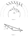
- Figure 3 Schematic representation of a section of one of the rows of guide vanes and a partial section of the rotor blades by a plane perpendicular to the rotational axis.
- the stator blades (17) (that coincide with the guide vanes (7) or (8) shown in Fig. 1 ) may be streamlined, as shown in the figure, or may be more simply made of bent plate.
- the guide vane curvature and setting angle are such that the incoming flow is deflected and forced to swirl in the same direction as the direction F of the rotor motion.
- FIG. 4 Velocity diagram, at a given time, close to the rotor inlet.
- Vector U is the rotor peripheric velocity.
- Vector V is the averaged flow velocity in a fixed frame of reference, and makes an angle C with a plane perpendicular to the axis of rotation.
- Vector W is the relative flow velocity in a rotor-fixed frame of reference, and makes an angle A with a plane perpendicular to the axis of rotation.
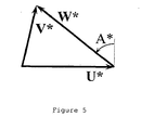
- FIG 5 Velocity diagram at the exit from the rotor at the same time as Fig.
- Vector U* is the rotor peripheric velocity.
- Vector V* is the averaged flow velocity in a fixed frame of reference.
- Vector W* is the relative flow velocity in a rotor-fixed frame of reference and makes an angle A* with a plane perpendicular to the rotational axis.
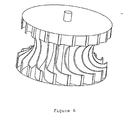
- FIG. 6 Schematic representation of the bladed rotor in perspective, without outer casing as in Fig. 2 .
- FIG. 7 Schematic representation of the turbine, with rotor as in Fig. 1 , but with two rows of guide vanes that can slide axially, in such a way that each guide vane row can be inserted into, or removed from, the flow space, depending on the reversing flow direction.
- the figure represents the preferred arrangement, in which the two guide vane rows are fixed to each other, so that, whenever one of the rows is inserted into the flow space, the other one is removed from it.
- Figure 8 Representation, as in Fig. 3 , of a partial section of one guide vane row and the rotor blades by a plane perpendicular to the rotational axis, corresponding to the arrangement shown in Fig. 7 .
- the radial gap between the rotor and the guide vanes is small, and the guide vane row can move axially.
- the figure represents the situation when the fluid is flowing into the rotor, because, in principle, the guide vanes should be removed from the flow space where the fluid is flowing out of the rotor.
- This invention concerns a turbine that, without change in its rotational direction, is capable of operating efficiently in bi-directional flow. For this reason, the turbine may be used in applications with reversing flow, as is the case of oscillating water column wave energy devices, or more generally in situations involving reciprocating flows, like in some renewable energy technologies or in other applications.
- the turbine is schematically represented in Fig. 1 , in a cross section by a plane containing the axis of rotation (1).
- the rotor blades (2) and the guide vanes (7, 8) are circumferentially projected onto the plane of the figure.
- the rotor comprehends a set of blades (2) fixed to a hub (3) mounted on a shaft (4).
- the admission of fluid into, and exit from, the rotor takes place at (5) and (6), or vice-versa, depending on the direction of the reciprocating bi-directional flow through the turbine.
- the stator comprehends two rows of guide vanes (7) and (8), circumferentially disposed around the rotor, located in the radial alignment of the respective rotor openings (5) and (6).
- connection between guide vane row (7) and rotor opening (5) is provided by a duct (9) with walls of revolution (10) and (11).
- One of these walls, or both, may be shaped as a flat disc.
- Identical description applies to connecting duct (12) and walls of revolution (13) and (14).
- all these walls, (10), (11), (13) and (14), are represented as flat discs.
- the ducts between rotor blades are bounded externally by a casing of revolution, which may be rigidly fixed to the rotor blades, as shown in (15), Fig. 1 , or may be part of the stator, as represented in (16) in Fig. 2 .
- Figure 3 schematically represents a section of one of the rows of guide vanes and a partial section of the rotor blades by a plane perpendicular to the rotational axis.
- the stator guide vanes (17) (that coincide with the guide vanes (7) or (8) in Fig. 1 ) may be streamlined, as shown in Fig. 3 , or may be more simply made of curved plate.
- the guide vane curvature and setting angle are such that the incoming flow is deflected and made to swirl in the same direction as the direction F of the rotor motion.
- the rotor blades, close to their inlet/outlet edge, are inclined, with respect to a plane perpendicular to the axis of rotation, by an angle B opposite to the direction F of motion of the rotor.
- Figure 4 represents the velocity diagram, at a given time, close to the rotor inlet.
- Vector U is the rotor peripheric velocity and its modulus is equal to the product of the rotor outer radius and the rotational velocity in radians per unit time.
- Vector V is the averaged flow velocity in a fixed frame of reference.
- Angle C between velocity vector V and a plane perpendicular to the rotational axis depends essentially on the stator geometry, especially the geometry of the guide vane system and the geometry of the connecting duct with walls of revolution.
- the modulus of vector V depends on the flow rate through the turbine.
- Vector W is the relative flow velocity in a rotor-fixed frame of reference, and results from subtracting vector U from vector V.
- Angle A between the relative flow velocity vector W and a plane perpendicular to the axis of rotation depends on the V/U ratio between the modules of velocities V and U (i.e. depends on the ratio between the flow rate and the rotational speed), and also on the angle C of velocity V.
- the angle A of the relative flow velocity at rotor inlet should not be much different from angle B of the rotor blades themselves, in which situation the boundary layer separation at the rotor blades' leading edge is minimized. This condition implies that angle B of the rotor blades should be significantly smaller that angle C of velocity V.
- the same condition also defines a design relationship between, on the one hand, the nominal flow rate and the nominal rotational speed, and, on the other hand, the geometry of the guide vanes, the geometry of the connecting duct and the geometry of the rotor blades (especially the inlet angle of the rotor blades).
- Figure 5 represents, at the same time as Fig. 4 , the velocity diagram at the exit from the rotor.
- the symbols are identical to those of Fig. 4 , with an asterisk for distinction.
- the angle A* between the relative flow velocity at rotor exit and a plane perpendicular to the rotational axis, is approximately equal to the angle B* of the blades at rotor exit.
- This equation shows that angles A and A* should conveniently be positive and not small. Typically, they could range between 30 and 60 degrees.
- Figure 6 schematically represents, in perspective, the rotor blades. These blades should meet the specified inlet and outlet angles. Their number and geometry should allow the relative flow to be adequately guided throughout the rotor.
- the rotor blades can be of constant or variable thickness, and their edges can be rounded, depending on aerodynamic or hydrodynamic considerations and on fabrication convenience.
- the guide vanes are fixed.
- the setting angle of the guide vanes can be adjusted to match the variations in direction and magnitude of the reversing flow rate. This is done jointly for all the guide vanes of each row, by means of a mechanism possibly consisting of a ring and articulated rods acted upon by a servomotor, as in the wicket gate system of the conventional Francis and Kaplan hydraulic turbines.
- An alternative way of avoiding the losses due to excessive incidence at the inlet to the second row of guide vanes is simply to remove those vanes from the flow space. This can be done by axial translation.of the two rows of guide vanes in such a way that each row can be inserted into, or removed from, the flow space, depending on the direction of the reversing flow.
- the two rows of guide vanes ((18) and (19) in Fig. 7 ) are rigidly connected to each other and, when one of them is inside the flow space, the other one is out of it.
- the axial motion should be controlled in such a way that it is completed in a short period of time, whenever the direction of the flow is reversed.
- the fluid should pass through a row of guide vanes before entering the rotor, but not after coming out of it. Due to the reversing nature of the flow, each of the two rows of guide vanes is successively inserted into, and removed from, the flow space. Because in this arrangement no losses due to stalling occur at the second row of guide vanes, there is no advantage in radially offsetting the guide vanes away from the rotor. So, the radial gap between the rotor and the guide vanes should preferably be small, as schematically represented in Figs 7 and 8 .
- the axial translational motion of the guide vane set can be produced by hydraulic, pneumatic, electrical or other action, or by gravity if the axis of rotation is sufficiently inclined with respect to the horizontal plane.
- U U*
- B B*.
Landscapes
- Engineering & Computer Science (AREA)
- Chemical & Material Sciences (AREA)
- Combustion & Propulsion (AREA)
- Mechanical Engineering (AREA)
- General Engineering & Computer Science (AREA)
- Hydraulic Turbines (AREA)
- Other Liquid Machine Or Engine Such As Wave Power Use (AREA)
- Turbine Rotor Nozzle Sealing (AREA)
- Structures Of Non-Positive Displacement Pumps (AREA)
Applications Claiming Priority (2)
| Application Number | Priority Date | Filing Date | Title |
|---|---|---|---|
| PT104972A PT104972B (pt) | 2010-02-19 | 2010-02-19 | Turbina com rotor de entrada e saída radiais para aplicações em escoamentos bidireccionados |
| PCT/PT2011/000003 WO2011102746A2 (fr) | 2010-02-19 | 2011-02-15 | Turbine avec rotor à entrée et sortie radiales trouvant une application dans des écoulements bidirectionnels |
Publications (2)
| Publication Number | Publication Date |
|---|---|
| EP2538070A2 true EP2538070A2 (fr) | 2012-12-26 |
| EP2538070B1 EP2538070B1 (fr) | 2015-10-14 |
Family
ID=44483514
Family Applications (1)
| Application Number | Title | Priority Date | Filing Date |
|---|---|---|---|
| EP11710901.7A Active EP2538070B1 (fr) | 2010-02-19 | 2011-02-15 | Turbine avec rotor a entree et sortie radiales trouvant une application dans des ecoulements bidirectionnels |
Country Status (8)
| Country | Link |
|---|---|
| US (1) | US9371815B2 (fr) |
| EP (1) | EP2538070B1 (fr) |
| AU (1) | AU2011216558B2 (fr) |
| CL (1) | CL2012002280A1 (fr) |
| ES (1) | ES2559444T3 (fr) |
| NZ (1) | NZ602493A (fr) |
| PT (1) | PT104972B (fr) |
| WO (1) | WO2011102746A2 (fr) |
Cited By (2)
| Publication number | Priority date | Publication date | Assignee | Title |
|---|---|---|---|---|
| PT106943A (pt) * | 2013-05-16 | 2014-11-17 | Inst Superior Tecnico | Turbina de ar para aplicações em aproveitamentos de energia das ondas |
| WO2014197234A1 (fr) * | 2013-06-03 | 2014-12-11 | Dresser-Rand Company Ltd. | Soupape d'arrêt pour turbines de colonnes d'eau oscillante |
Families Citing this family (10)
| Publication number | Priority date | Publication date | Assignee | Title |
|---|---|---|---|---|
| DE102010018804A1 (de) * | 2010-04-29 | 2011-11-03 | Voith Patent Gmbh | Wasserturbine |
| US9709022B2 (en) * | 2012-05-04 | 2017-07-18 | Reginald Friedenthal | Apparatus for generating energy |
| ES2656642T3 (es) * | 2012-10-02 | 2018-02-27 | Dresser-Rand Company | Turbina con entrada y salida radial y álabes de guía de múltiples elementos para flujos oscilantes |
| CN104863642B (zh) * | 2015-06-12 | 2016-06-15 | 西华大学 | 一种小流量涡轮膨胀机 |
| PT109624B (pt) | 2016-09-22 | 2021-06-04 | Inst Superior Tecnico | Sistema de conversão de energia em escoamentos alternados bidirecionais e o seu método de funcionamento |
| EP3863761A4 (fr) * | 2018-10-10 | 2022-07-27 | Coolbrook Oy | Dispositif rotatif pour exécuter des réactions chimiques |
| ES2827648A1 (es) * | 2019-11-21 | 2021-05-21 | Univ Oviedo | Turbina radial con bloqueo del flujo reverso y sistema de generación de energía extraída de flujos bidireccionales |
| JP2023148469A (ja) * | 2022-03-30 | 2023-10-13 | ダイキン工業株式会社 | 流体機械 |
| US12209596B2 (en) * | 2022-09-27 | 2025-01-28 | Cisco Technology, Inc. | Configurable bi-directional airflow fan |
| KR102858550B1 (ko) * | 2025-07-15 | 2025-09-10 | 국립한국해양대학교산학협력단 | 바이래디얼 터빈블레이드 제어시스템 |
Family Cites Families (26)
| Publication number | Priority date | Publication date | Assignee | Title |
|---|---|---|---|---|
| US557802A (en) * | 1896-04-07 | Turbine water-wheel | ||
| US1478054A (en) * | 1919-05-22 | 1923-12-18 | William Cramp & Sons Ship And | Guide vane for hydraulic turbines |
| US1357440A (en) * | 1919-11-20 | 1920-11-02 | Morgan Smith S Co | Wicket-gate for water-wheels |
| US1509587A (en) * | 1922-11-28 | 1924-09-23 | William M Vastine | Water turbine |
| US1587608A (en) * | 1925-04-13 | 1926-06-08 | Arthur R Siegler | Fluid-turbine rotor |
| US1900144A (en) * | 1930-09-02 | 1933-03-07 | William M White | Hydraulic machine |
| US2484554A (en) * | 1945-12-20 | 1949-10-11 | Gen Electric | Centrifugal impeller |
| GB1020383A (en) * | 1962-03-05 | 1966-02-16 | English Electric Co Ltd | Control systems for hydraulic pumps and pump-turbines |
| GB1042509A (en) * | 1962-07-31 | 1966-09-14 | English Electric Co Ltd | Improvements in or relating to hydraulic reaction turbine alternator sets |
| US3210045A (en) * | 1963-05-09 | 1965-10-05 | Nydqvist & Holm Ab | Device for wicket guide stems for water turbines, pump turbines or pumps |
| NO119216B (fr) * | 1965-04-12 | 1970-04-06 | Nydqvist & Holm Ab | |
| US3922739A (en) | 1974-04-18 | 1975-12-02 | Ivan Andreevich Babintsev | Apparatus for converting sea wave energy into electrical energy |
| DE2531652A1 (de) * | 1974-07-19 | 1976-01-29 | David Agnelo Goncalves | Verfahren und anlage zur umwandlung der mechanischen energie der meereswellen in als natuerliche energie verwendbare antriebsleistung |
| US4271668A (en) * | 1979-10-17 | 1981-06-09 | Mccormick Michael E | Counter-rotating wave energy conversion turbine |
| CH659851A5 (de) * | 1981-06-05 | 1987-02-27 | Escher Wyss Ag | Turbine. |
| JPS58220973A (ja) * | 1982-06-17 | 1983-12-22 | Mitsubishi Electric Corp | 往復流中で同一方向に回転するタ−ビン装置 |
| US4599041A (en) * | 1984-12-19 | 1986-07-08 | Stricker John G | Variable camber tandem blade bow for turbomachines |
| FR2611228B1 (fr) * | 1987-02-20 | 1990-05-25 | Boussuges Pierre | Turbine centrifuge a action |
| JPH0264270A (ja) * | 1988-08-31 | 1990-03-05 | Saga Univ | 自己可変ピッチ案内羽根を有する衝動タービン |
| GB9108152D0 (en) * | 1991-04-17 | 1991-06-05 | Applied Res & Tech | Wave energy converter |
| GB9221917D0 (en) * | 1992-10-19 | 1992-12-02 | Applied Res & Tech | Electric power generator |
| ITCE20020009A1 (it) * | 2002-09-30 | 2002-12-30 | Giuseppe Ferraro | Dispositivo a girante palettata reversibile con motore/generatore elettrico "senza spazzole" per la gestione dell'aria di sovralimentazione |
| GB2440344A (en) * | 2006-07-26 | 2008-01-30 | Christopher Freeman | Impulse turbine design |
| JP4805783B2 (ja) * | 2006-10-10 | 2011-11-02 | 東陽設計工業株式会社 | 波力発電用タービン |
| US8670881B2 (en) | 2007-03-14 | 2014-03-11 | General Electric Company | Flight management system for generating variable thrust cutback during aircraft departure |
| US8030789B2 (en) * | 2008-11-07 | 2011-10-04 | Israel Ortiz | Wave turbine |
-
2010
- 2010-02-19 PT PT104972A patent/PT104972B/pt active IP Right Grant
-
2011
- 2011-02-15 EP EP11710901.7A patent/EP2538070B1/fr active Active
- 2011-02-15 ES ES11710901.7T patent/ES2559444T3/es active Active
- 2011-02-15 US US13/580,099 patent/US9371815B2/en active Active
- 2011-02-15 NZ NZ60249311A patent/NZ602493A/en unknown
- 2011-02-15 AU AU2011216558A patent/AU2011216558B2/en active Active
- 2011-02-15 WO PCT/PT2011/000003 patent/WO2011102746A2/fr not_active Ceased
-
2012
- 2012-08-17 CL CL2012002280A patent/CL2012002280A1/es unknown
Non-Patent Citations (1)
| Title |
|---|
| See references of WO2011102746A2 * |
Cited By (5)
| Publication number | Priority date | Publication date | Assignee | Title |
|---|---|---|---|---|
| PT106943A (pt) * | 2013-05-16 | 2014-11-17 | Inst Superior Tecnico | Turbina de ar para aplicações em aproveitamentos de energia das ondas |
| WO2014185806A1 (fr) * | 2013-05-16 | 2014-11-20 | Instituto Superior Técnico | Turbine à air pour des applications dans une conversion d'énergie des vagues |
| AU2014266027B2 (en) * | 2013-05-16 | 2018-01-04 | Instituto Superior Tecnico | Air turbine for applications in wave energy conversion |
| WO2014197234A1 (fr) * | 2013-06-03 | 2014-12-11 | Dresser-Rand Company Ltd. | Soupape d'arrêt pour turbines de colonnes d'eau oscillante |
| US9709023B2 (en) | 2013-06-03 | 2017-07-18 | Dresser-Rand Company | Shut off valve for oscillating water column turbines |
Also Published As
| Publication number | Publication date |
|---|---|
| WO2011102746A3 (fr) | 2012-01-12 |
| ES2559444T3 (es) | 2016-02-12 |
| WO2011102746A4 (fr) | 2012-03-15 |
| WO2011102746A2 (fr) | 2011-08-25 |
| NZ602493A (en) | 2014-10-31 |
| US9371815B2 (en) | 2016-06-21 |
| PT104972B (pt) | 2017-10-25 |
| US20130011251A1 (en) | 2013-01-10 |
| AU2011216558B2 (en) | 2016-02-04 |
| AU2011216558A1 (en) | 2012-09-27 |
| EP2538070B1 (fr) | 2015-10-14 |
| CL2012002280A1 (es) | 2013-05-17 |
Similar Documents
| Publication | Publication Date | Title |
|---|---|---|
| EP2538070B1 (fr) | Turbine avec rotor a entree et sortie radiales trouvant une application dans des ecoulements bidirectionnels | |
| US5451138A (en) | Unidirecional reaction turbine operable under reversible fluid from flow | |
| AU2007279098B2 (en) | Impulse turbine for use in bi-directional flows | |
| CN107514290B (zh) | 一种适用于亚洲海域振荡水柱式波能发电装置的非对称式空气透平 | |
| US20130192219A1 (en) | Energy conversion system with self-rectifying radial flow turbine and method | |
| US20090015018A1 (en) | Flow Stream Momentum Conversion Device Power Rotor | |
| RU2391554C1 (ru) | Низконапорная ортогональная турбина | |
| EP2997252B1 (fr) | Turbine à air pour installation houlomotrice | |
| CA2790124C (fr) | Disposition d'une turbine a air pulse servant a un debit bidirectionnel inverse dans une installation de production d'energie a partir de la houle | |
| JP3898311B2 (ja) | 水車またはポンプ水車 | |
| RU2462612C1 (ru) | Ортогональный энергетический агрегат для преобразования энергии потоков воды или воздуха | |
| US1748892A (en) | Hydraulic process and apparatus | |
| CN207406382U (zh) | 一种适用于亚洲海域振荡水柱式波能发电装置的非对称式空气透平 | |
| KR100720909B1 (ko) | 회전익 날개 끝 간극유동 손실 방지용 임펄스 터빈 | |
| Karthikeyan et al. | Review of air turbines for wave energy conversion | |
| JP6354051B2 (ja) | 波力発電タービン | |
| JP2015203395A (ja) | 波力発電タービン |
Legal Events
| Date | Code | Title | Description |
|---|---|---|---|
| PUAI | Public reference made under article 153(3) epc to a published international application that has entered the european phase |
Free format text: ORIGINAL CODE: 0009012 |
|
| 17P | Request for examination filed |
Effective date: 20120905 |
|
| AK | Designated contracting states |
Kind code of ref document: A2 Designated state(s): AL AT BE BG CH CY CZ DE DK EE ES FI FR GB GR HR HU IE IS IT LI LT LU LV MC MK MT NL NO PL PT RO RS SE SI SK SM TR |
|
| 111L | Licence recorded |
Designated state(s): AL AT BE BG CH CY CZ DE DK EE ES FI FR GB GR HR HU IE IS IT LT LU LV MC MK MT NL NO PL PT RO RS SE SI SK SM TR Free format text: EXCLUSIVE LICENSE Name of requester: KYMANER - TECNOLOGIAS ENERGETICAS, LDA, PT Effective date: 20130206 |
|
| DAX | Request for extension of the european patent (deleted) | ||
| GRAP | Despatch of communication of intention to grant a patent |
Free format text: ORIGINAL CODE: EPIDOSNIGR1 |
|
| RIC1 | Information provided on ipc code assigned before grant |
Ipc: F03B 13/14 20060101ALI20150416BHEP Ipc: F03B 3/12 20060101AFI20150416BHEP Ipc: F03B 13/22 20060101ALI20150416BHEP Ipc: F03B 3/18 20060101ALI20150416BHEP |
|
| INTG | Intention to grant announced |
Effective date: 20150504 |
|
| GRAS | Grant fee paid |
Free format text: ORIGINAL CODE: EPIDOSNIGR3 |
|
| GRAA | (expected) grant |
Free format text: ORIGINAL CODE: 0009210 |
|
| 111L | Licence recorded |
Designated state(s): AL AT BE BG CH CY CZ DE DK EE ES FI FR GB GR HR HU IE IS IT LT LU LV MC MK MT NL NO PL PT RO RS SE SI SK SM TR Free format text: EXCLUSIVE LICENSE Name of requester: KYMANER - TECNOLOGIAS ENERGETICAS, LDA, PT Effective date: 20130206 |
|
| AK | Designated contracting states |
Kind code of ref document: B1 Designated state(s): AL AT BE BG CH CY CZ DE DK EE ES FI FR GB GR HR HU IE IS IT LI LT LU LV MC MK MT NL NO PL PT RO RS SE SI SK SM TR |
|
| REG | Reference to a national code |
Ref country code: GB Ref legal event code: FG4D |
|
| REG | Reference to a national code |
Ref country code: AT Ref legal event code: REF Ref document number: 755321 Country of ref document: AT Kind code of ref document: T Effective date: 20151015 Ref country code: CH Ref legal event code: PK Free format text: ERGAENZUNG LIZENZEINTRAG: AUSSCHLIESSLICHE LIZENZ Ref country code: CH Ref legal event code: EP |
|
| REG | Reference to a national code |
Ref country code: IE Ref legal event code: FG4D |
|
| REG | Reference to a national code |
Ref country code: DE Ref legal event code: R096 Ref document number: 602011020573 Country of ref document: DE |
|
| REG | Reference to a national code |
Ref country code: ES Ref legal event code: FG2A Ref document number: 2559444 Country of ref document: ES Kind code of ref document: T3 Effective date: 20160212 |
|
| REG | Reference to a national code |
Ref country code: NL Ref legal event code: MP Effective date: 20151014 |
|
| REG | Reference to a national code |
Ref country code: LT Ref legal event code: MG4D |
|
| REG | Reference to a national code |
Ref country code: NO Ref legal event code: T2 Effective date: 20151014 |
|
| REG | Reference to a national code |
Ref country code: AT Ref legal event code: MK05 Ref document number: 755321 Country of ref document: AT Kind code of ref document: T Effective date: 20151014 |
|
| REG | Reference to a national code |
Ref country code: FR Ref legal event code: PLFP Year of fee payment: 6 |
|
| PG25 | Lapsed in a contracting state [announced via postgrant information from national office to epo] |
Ref country code: HR Free format text: LAPSE BECAUSE OF FAILURE TO SUBMIT A TRANSLATION OF THE DESCRIPTION OR TO PAY THE FEE WITHIN THE PRESCRIBED TIME-LIMIT Effective date: 20151014 Ref country code: IS Free format text: LAPSE BECAUSE OF FAILURE TO SUBMIT A TRANSLATION OF THE DESCRIPTION OR TO PAY THE FEE WITHIN THE PRESCRIBED TIME-LIMIT Effective date: 20160214 Ref country code: LT Free format text: LAPSE BECAUSE OF FAILURE TO SUBMIT A TRANSLATION OF THE DESCRIPTION OR TO PAY THE FEE WITHIN THE PRESCRIBED TIME-LIMIT Effective date: 20151014 Ref country code: NL Free format text: LAPSE BECAUSE OF FAILURE TO SUBMIT A TRANSLATION OF THE DESCRIPTION OR TO PAY THE FEE WITHIN THE PRESCRIBED TIME-LIMIT Effective date: 20151014 |
|
| PG25 | Lapsed in a contracting state [announced via postgrant information from national office to epo] |
Ref country code: AT Free format text: LAPSE BECAUSE OF FAILURE TO SUBMIT A TRANSLATION OF THE DESCRIPTION OR TO PAY THE FEE WITHIN THE PRESCRIBED TIME-LIMIT Effective date: 20151014 Ref country code: RS Free format text: LAPSE BECAUSE OF FAILURE TO SUBMIT A TRANSLATION OF THE DESCRIPTION OR TO PAY THE FEE WITHIN THE PRESCRIBED TIME-LIMIT Effective date: 20151014 Ref country code: PT Free format text: LAPSE BECAUSE OF FAILURE TO SUBMIT A TRANSLATION OF THE DESCRIPTION OR TO PAY THE FEE WITHIN THE PRESCRIBED TIME-LIMIT Effective date: 20160215 Ref country code: FI Free format text: LAPSE BECAUSE OF FAILURE TO SUBMIT A TRANSLATION OF THE DESCRIPTION OR TO PAY THE FEE WITHIN THE PRESCRIBED TIME-LIMIT Effective date: 20151014 Ref country code: PL Free format text: LAPSE BECAUSE OF FAILURE TO SUBMIT A TRANSLATION OF THE DESCRIPTION OR TO PAY THE FEE WITHIN THE PRESCRIBED TIME-LIMIT Effective date: 20151014 Ref country code: SE Free format text: LAPSE BECAUSE OF FAILURE TO SUBMIT A TRANSLATION OF THE DESCRIPTION OR TO PAY THE FEE WITHIN THE PRESCRIBED TIME-LIMIT Effective date: 20151014 Ref country code: BE Free format text: LAPSE BECAUSE OF NON-PAYMENT OF DUE FEES Effective date: 20160229 Ref country code: LV Free format text: LAPSE BECAUSE OF FAILURE TO SUBMIT A TRANSLATION OF THE DESCRIPTION OR TO PAY THE FEE WITHIN THE PRESCRIBED TIME-LIMIT Effective date: 20151014 |
|
| REG | Reference to a national code |
Ref country code: DE Ref legal event code: R097 Ref document number: 602011020573 Country of ref document: DE |
|
| PG25 | Lapsed in a contracting state [announced via postgrant information from national office to epo] |
Ref country code: CZ Free format text: LAPSE BECAUSE OF FAILURE TO SUBMIT A TRANSLATION OF THE DESCRIPTION OR TO PAY THE FEE WITHIN THE PRESCRIBED TIME-LIMIT Effective date: 20151014 |
|
| PLBE | No opposition filed within time limit |
Free format text: ORIGINAL CODE: 0009261 |
|
| STAA | Information on the status of an ep patent application or granted ep patent |
Free format text: STATUS: NO OPPOSITION FILED WITHIN TIME LIMIT |
|
| PG25 | Lapsed in a contracting state [announced via postgrant information from national office to epo] |
Ref country code: SM Free format text: LAPSE BECAUSE OF FAILURE TO SUBMIT A TRANSLATION OF THE DESCRIPTION OR TO PAY THE FEE WITHIN THE PRESCRIBED TIME-LIMIT Effective date: 20151014 Ref country code: DK Free format text: LAPSE BECAUSE OF FAILURE TO SUBMIT A TRANSLATION OF THE DESCRIPTION OR TO PAY THE FEE WITHIN THE PRESCRIBED TIME-LIMIT Effective date: 20151014 Ref country code: EE Free format text: LAPSE BECAUSE OF FAILURE TO SUBMIT A TRANSLATION OF THE DESCRIPTION OR TO PAY THE FEE WITHIN THE PRESCRIBED TIME-LIMIT Effective date: 20151014 Ref country code: SK Free format text: LAPSE BECAUSE OF FAILURE TO SUBMIT A TRANSLATION OF THE DESCRIPTION OR TO PAY THE FEE WITHIN THE PRESCRIBED TIME-LIMIT Effective date: 20151014 Ref country code: RO Free format text: LAPSE BECAUSE OF FAILURE TO SUBMIT A TRANSLATION OF THE DESCRIPTION OR TO PAY THE FEE WITHIN THE PRESCRIBED TIME-LIMIT Effective date: 20151014 |
|
| REG | Reference to a national code |
Ref country code: DE Ref legal event code: R119 Ref document number: 602011020573 Country of ref document: DE |
|
| 26N | No opposition filed |
Effective date: 20160715 |
|
| PG25 | Lapsed in a contracting state [announced via postgrant information from national office to epo] |
Ref country code: LU Free format text: LAPSE BECAUSE OF FAILURE TO SUBMIT A TRANSLATION OF THE DESCRIPTION OR TO PAY THE FEE WITHIN THE PRESCRIBED TIME-LIMIT Effective date: 20160215 Ref country code: MC Free format text: LAPSE BECAUSE OF FAILURE TO SUBMIT A TRANSLATION OF THE DESCRIPTION OR TO PAY THE FEE WITHIN THE PRESCRIBED TIME-LIMIT Effective date: 20151014 |
|
| REG | Reference to a national code |
Ref country code: CH Ref legal event code: PL |
|
| PG25 | Lapsed in a contracting state [announced via postgrant information from national office to epo] |
Ref country code: LI Free format text: LAPSE BECAUSE OF NON-PAYMENT OF DUE FEES Effective date: 20160229 Ref country code: CH Free format text: LAPSE BECAUSE OF NON-PAYMENT OF DUE FEES Effective date: 20160229 |
|
| PG25 | Lapsed in a contracting state [announced via postgrant information from national office to epo] |
Ref country code: SI Free format text: LAPSE BECAUSE OF FAILURE TO SUBMIT A TRANSLATION OF THE DESCRIPTION OR TO PAY THE FEE WITHIN THE PRESCRIBED TIME-LIMIT Effective date: 20151014 |
|
| PG25 | Lapsed in a contracting state [announced via postgrant information from national office to epo] |
Ref country code: BE Free format text: LAPSE BECAUSE OF FAILURE TO SUBMIT A TRANSLATION OF THE DESCRIPTION OR TO PAY THE FEE WITHIN THE PRESCRIBED TIME-LIMIT Effective date: 20151014 |
|
| PG25 | Lapsed in a contracting state [announced via postgrant information from national office to epo] |
Ref country code: DE Free format text: LAPSE BECAUSE OF NON-PAYMENT OF DUE FEES Effective date: 20160901 |
|
| REG | Reference to a national code |
Ref country code: FR Ref legal event code: PLFP Year of fee payment: 7 |
|
| PG25 | Lapsed in a contracting state [announced via postgrant information from national office to epo] |
Ref country code: MT Free format text: LAPSE BECAUSE OF FAILURE TO SUBMIT A TRANSLATION OF THE DESCRIPTION OR TO PAY THE FEE WITHIN THE PRESCRIBED TIME-LIMIT Effective date: 20151014 |
|
| REG | Reference to a national code |
Ref country code: FR Ref legal event code: PLFP Year of fee payment: 8 |
|
| PG25 | Lapsed in a contracting state [announced via postgrant information from national office to epo] |
Ref country code: HU Free format text: LAPSE BECAUSE OF FAILURE TO SUBMIT A TRANSLATION OF THE DESCRIPTION OR TO PAY THE FEE WITHIN THE PRESCRIBED TIME-LIMIT; INVALID AB INITIO Effective date: 20110215 Ref country code: CY Free format text: LAPSE BECAUSE OF FAILURE TO SUBMIT A TRANSLATION OF THE DESCRIPTION OR TO PAY THE FEE WITHIN THE PRESCRIBED TIME-LIMIT Effective date: 20151014 |
|
| PG25 | Lapsed in a contracting state [announced via postgrant information from national office to epo] |
Ref country code: MK Free format text: LAPSE BECAUSE OF FAILURE TO SUBMIT A TRANSLATION OF THE DESCRIPTION OR TO PAY THE FEE WITHIN THE PRESCRIBED TIME-LIMIT Effective date: 20151014 Ref country code: TR Free format text: LAPSE BECAUSE OF FAILURE TO SUBMIT A TRANSLATION OF THE DESCRIPTION OR TO PAY THE FEE WITHIN THE PRESCRIBED TIME-LIMIT Effective date: 20151014 Ref country code: GR Free format text: LAPSE BECAUSE OF FAILURE TO SUBMIT A TRANSLATION OF THE DESCRIPTION OR TO PAY THE FEE WITHIN THE PRESCRIBED TIME-LIMIT Effective date: 20151014 Ref country code: MT Free format text: LAPSE BECAUSE OF FAILURE TO SUBMIT A TRANSLATION OF THE DESCRIPTION OR TO PAY THE FEE WITHIN THE PRESCRIBED TIME-LIMIT Effective date: 20160229 |
|
| PG25 | Lapsed in a contracting state [announced via postgrant information from national office to epo] |
Ref country code: BG Free format text: LAPSE BECAUSE OF FAILURE TO SUBMIT A TRANSLATION OF THE DESCRIPTION OR TO PAY THE FEE WITHIN THE PRESCRIBED TIME-LIMIT Effective date: 20151014 |
|
| PG25 | Lapsed in a contracting state [announced via postgrant information from national office to epo] |
Ref country code: AL Free format text: LAPSE BECAUSE OF FAILURE TO SUBMIT A TRANSLATION OF THE DESCRIPTION OR TO PAY THE FEE WITHIN THE PRESCRIBED TIME-LIMIT Effective date: 20151014 |
|
| PGFP | Annual fee paid to national office [announced via postgrant information from national office to epo] |
Ref country code: GB Payment date: 20260202 Year of fee payment: 16 |
|
| PGFP | Annual fee paid to national office [announced via postgrant information from national office to epo] |
Ref country code: ES Payment date: 20260311 Year of fee payment: 16 |
|
| PGFP | Annual fee paid to national office [announced via postgrant information from national office to epo] |
Ref country code: NO Payment date: 20260211 Year of fee payment: 16 Ref country code: IE Payment date: 20260123 Year of fee payment: 16 |
|
| PGFP | Annual fee paid to national office [announced via postgrant information from national office to epo] |
Ref country code: IT Payment date: 20260128 Year of fee payment: 16 |
|
| PGFP | Annual fee paid to national office [announced via postgrant information from national office to epo] |
Ref country code: FR Payment date: 20260209 Year of fee payment: 16 |