EP2538094A2 - Karabinerhaken - Google Patents
Karabinerhaken Download PDFInfo
- Publication number
- EP2538094A2 EP2538094A2 EP12004559A EP12004559A EP2538094A2 EP 2538094 A2 EP2538094 A2 EP 2538094A2 EP 12004559 A EP12004559 A EP 12004559A EP 12004559 A EP12004559 A EP 12004559A EP 2538094 A2 EP2538094 A2 EP 2538094A2
- Authority
- EP
- European Patent Office
- Prior art keywords
- closing part
- locking
- bracket
- closing
- snap hook
- Prior art date
- Legal status (The legal status is an assumption and is not a legal conclusion. Google has not performed a legal analysis and makes no representation as to the accuracy of the status listed.)
- Granted
Links
Images

Classifications
-
- F—MECHANICAL ENGINEERING; LIGHTING; HEATING; WEAPONS; BLASTING
- F16—ENGINEERING ELEMENTS AND UNITS; GENERAL MEASURES FOR PRODUCING AND MAINTAINING EFFECTIVE FUNCTIONING OF MACHINES OR INSTALLATIONS; THERMAL INSULATION IN GENERAL
- F16B—DEVICES FOR FASTENING OR SECURING CONSTRUCTIONAL ELEMENTS OR MACHINE PARTS TOGETHER, e.g. NAILS, BOLTS, CIRCLIPS, CLAMPS, CLIPS OR WEDGES; JOINTS OR JOINTING
- F16B45/00—Hooks; Eyes
- F16B45/02—Hooks with pivoting or elastically bending closing member
- F16B45/027—Hooks with pivoting or elastically bending closing member and having position-locking means for the closing member
- F16B45/029—Hooks with pivoting or elastically bending closing member and having position-locking means for the closing member the position-locking means being slidably mounted
-
- F—MECHANICAL ENGINEERING; LIGHTING; HEATING; WEAPONS; BLASTING
- F16—ENGINEERING ELEMENTS AND UNITS; GENERAL MEASURES FOR PRODUCING AND MAINTAINING EFFECTIVE FUNCTIONING OF MACHINES OR INSTALLATIONS; THERMAL INSULATION IN GENERAL
- F16B—DEVICES FOR FASTENING OR SECURING CONSTRUCTIONAL ELEMENTS OR MACHINE PARTS TOGETHER, e.g. NAILS, BOLTS, CIRCLIPS, CLAMPS, CLIPS OR WEDGES; JOINTS OR JOINTING
- F16B45/00—Hooks; Eyes
- F16B45/02—Hooks with pivoting or elastically bending closing member
- F16B45/023—Hooks with pivoting or elastically bending closing member the closing member pivoting about an axis perpendicular to the plane of the hook
-
- F—MECHANICAL ENGINEERING; LIGHTING; HEATING; WEAPONS; BLASTING
- F16—ENGINEERING ELEMENTS AND UNITS; GENERAL MEASURES FOR PRODUCING AND MAINTAINING EFFECTIVE FUNCTIONING OF MACHINES OR INSTALLATIONS; THERMAL INSULATION IN GENERAL
- F16B—DEVICES FOR FASTENING OR SECURING CONSTRUCTIONAL ELEMENTS OR MACHINE PARTS TOGETHER, e.g. NAILS, BOLTS, CIRCLIPS, CLAMPS, CLIPS OR WEDGES; JOINTS OR JOINTING
- F16B45/00—Hooks; Eyes
- F16B45/02—Hooks with pivoting or elastically bending closing member
- F16B45/024—Hooks with pivoting or elastically bending closing member and having means biasing the closing member about the pivot
Definitions
- the present invention relates to a snap hook with a, at least one receiving opening partially enclosing bracket and at least one, on the bracket about a Schröteilschwenkgelenk pivotally mounted closure member for closing the receiving opening of the bracket in the closed position of the closing part, wherein the receiving opening in at least one open position of the closing part from the outside is accessible and the snap hook additionally, slidably mounted on or on the closing part mounted locking member for locking the closing part in its closed position.
- Snap hooks are known in a variety of embodiments and are also used in a variety of applications.
- here are the mountain sports, aviation and occupational safety. Often it is important for safety reasons that the closure member can not be accidentally pivoted from its closed position to one of its open positions.
- Generic solutions, as they, for example, in the DE 296 10 293 U1 are shown are widely used.
- a locking member is slidably mounted on the closure member. The locking member holds in its locking position, the closing part in its closed position and thereby prevents pivoting of the closing part in one of its open positions.
- the object of the invention is to develop generic snap hooks.
- the locking member is pivotally supported at least in a first operating position by means of a locking part pivot joint on the bracket.
- An essential idea of the invention is therefore to provide, in addition to the closing part pivot joint, a second joint in the form of the blocking part pivot joint, by means of which the blocking part can be held pivotably on the bracket in at least one first operating position.
- the Sperrteilschwenkgelenk can be used to automatically move the locking part on actuation of the closing part on this and / or hold in a retracted position when the closing part is in an open position.
- embodiments of the invention can also be used to reduce the required number of elastic return elements. So it is e.g. possible that the snap hook only exactly one elastic return element for biasing the closing part in the direction of its closed position and to bias the locking member toward its locking position in which the locking member locks the closing part comprises. In these embodiments, the elastic return element thus biases both the closing part and the locking part. On separate return elements for closing and locking part can be omitted in these embodiments.
- snap hooks according to the invention can also be equipped with at least one elastic restoring element for the closing part and the blocking part.
- Particularly preferred embodiments of the invention provide that the Sperrteilschwenkgelenk at least a first, fixed to the locking part Sperrteilschwenkgelenkteil and at least one further fixedly arranged on the bracket Sperrteilschwenkgelenkteil, wherein the Sperrteilschwenkgelenkmaschinee are pivotally mounted in the first operating position for forming the Sperrteilschwenkgelenks together and in at least a further operating position, in particular in the closed position of the closing part, are separated from each other.
- operating positions are provided in which the locking part pivot joint parts are separated from each other and thus the locking member not by means the Sperrteilschwenkgelenks is held on the bracket.
- the locking part if it is to lock the closure member in the closed position, is not pivotally held on the bracket. This ensures that the user of the snap hook must first deliberately actuate the locking part for locking the closing part and only then, when the locking part pivotal articulation engage each other and are pivotally mounted to each other, the locking member automatically moves together with the closing part or in the open position, in the it is not locked the locking part is held.
- the Sperrteilschwenkgelenk at least a first, fixedly arranged on the locking part Sperrteilschwenkgelenkteil and at least one further fixedly arranged on the bracket Sperrteilschwenkgelenkteil, wherein one of the Sperrteilschwenkgelenkmaschinea axle and the other of the Sperrteilschwenkgelenkmaschine a Achsbolzenlager for rotatable Has or is storage of the axle.
- the locking part is a closing part at least partially, preferably completely, comprehensive sliding sleeve.
- the sliding sleeve in the closed position of the closing part for locking the closing part also includes an end, preferably an end pin, of the bracket.
- the locking member may also be used in addition to locking the closure member in its closed position to stabilize the closure member as a whole.
- the snap hook preferred embodiments of the invention provide that, preferably designed as a helical spring, elastic return element is disposed in an interior of the locking member and / or the closing part.
- the elastic restoring element designed in particular as a helical spring can be arranged spatially between the blocking part and the closing part and / or act on the blocking part and the closing part.
- Particularly preferred embodiments provide that the elastic return element is clamped between locking part and closing part.
- the Sch josteilschwenkgelenk advantageously has a permanently fixed or fixedly arranged on the bracket Sch physicallyteilschwenkgelenkachse about which the closing part between its closed position and its open positions is pivotable back and forth.
- the closing part is pivotable about a Sch thoroughlyteilschwenkgelenkachse and the locking part is pivotable about a Sperrteilschwenkgelenkachse and the Sch thoroughlyteilschwenkgelenkachse and the Sperrteilschwenkgelenkachse in at least one operating position, preferably in all operating positions, spaced from each other.
- the Sperrteilschwenkgelenkachse is in these embodiments, in other words, thus arranged eccentrically with respect to the Sch thoroughlyteilschwenkgelenkachse.
- Particularly preferred embodiments provide in this context that the Sperrteilschwenkgelenkachse is disposed on a side facing away from the receiving opening side of the Sch thoroughlyteilschwenkgelenkachse.
- a distant arrangement means an arrangement with a distance greater than zero.
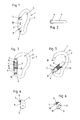
- Fig. 1 the snap hook 1 according to the invention of the first embodiment is shown in a perspective view. Shown is the bracket 3, on which by means of the closing part pivot joint 4, the closing part 5 is pivotally mounted about the Sch thoroughlyteilschwenkgelenkachse 12.
- Fig. 1 is the closing part 5 in its closed position in which it includes the receiving opening 2 circumferentially closed together with the bracket 3. Around a loop, a rope or To be able to insert the same into the receiving opening 2, the closing part 5 must be pivoted in one of its open positions around the Sch thoroughlyteilschwenkgelenkachse 12.
- the locking part 6 designed here as a sliding sleeve from its locking position Fig. 1 be moved.
- the blocking part 6 is displaceably mounted on or on the closing part 5, or in other words in the longitudinal directions 18 of the closing part 5 on or on this slidably mounted.
- the locked position according to Fig. 1 and 3 locks or blocks the locking member 6, the closing part 5 in its closed position and thus prevents accidental pivoting of the closing part 5 in one of its open positions.
- Fig. 2 shows a plan view from above on the snap hook 1 according to Fig. 1.
- Fig. 3 shows a side view of the snap hook 1, wherein the locking member 6 is shown in section.
- Fig. 3 is the locking member 6 in its locked position in which it holds the closing part 5 in its closed position.
- Fig. 5 it is an analog representation, however, the closing member 5 is here in its maximum open position.
- the blocking part 6 is in Fig. 5 held by the Sperrteilschwenkgelenk 7 in a retracted position.
- an elastic return element 10 here in the form of a coil spring, in this embodiment, both on the locking member 6 and on the closing part 5 a. It is clamped between an upper support shoulder 14 and a lower support shoulder 15. The upper support shoulder 14 is fixedly connected to the locking part 6. The lower support shoulder 15 is fixedly attached to the closing part 5.
- the elastic return element 10 is guided around the closing part 5 and arranged in an inner space 11 of the locking part 6.
- the blocking part 6 is at least in a first operating position, here by way of example the operating position according to FIG Fig. 5 ,
- the Sperrteilschwenkgelenk 7 is formed in the embodiment shown by a first Sperrteilschwenkgelenkteil in the form of an axle 8 and another Sperrteilschwenkgelenkteils 9 in the form of a Achsbolzenlagers for rotatably supporting the axle.
- the first Sperrteilschwenkgelenkteil 8 fixed in the form of the axle bolt on the locking part 6.
- the further Sperrteilschwenkgelenkteil 9 in the form of Achsbolzenlagers is fixedly arranged in this embodiment on the bracket 3. But this need not be so, a reverse embodiment is also possible, to give an example.
- the Sperrteilschwenkgelenkteil 8 may be arranged in the form of the axle bolt on the bracket 3 and the other Sperrteilschwenkgelenkteil 9 in the form of Achsbolzenlagers also on the locking part 6.
- Fig. 4 shows area A Fig. 3 increased.
- Fig. 6 shows area B Fig. 5 increased.
- the two Sperrteilschwenkgelenkmaschine 8 and 9 are not permanently engaged with each other, but the Sperrteilschwenkgelenk 7 only acts in certain operating positions as a joint.
- the closed position of the closing part 5 according to the Fig. 1, 3 and 4 engage the two Sperrteilschwenkgelenkmaschine 8 and 9 not into each other, in the open position of the closing part 5 according to FIGS. 5 and 6 beautiful.
- the closing part 5 Upon further pivoting of the closing part 5 in the direction of its maximum open position according to Fig. 5 holds the Sperrteilschwenkgelenk 7 then the locking member 6 automatically in a retracted position or pulls this even further back toward the Sch thoroughlyteilschwenkgelenks 4.
- the closing part 5 of course, not always in its maximum open position according to Fig. 5 has to be swiveled.
- the elastic restoring element 10 under tension ensures both the return of the closing part 5 into its closed position and the blocking part 6 into its locking position.
- This return movement keeps the Sperrteilschwenkgelenk 7 the locking member 6 so long back, as long as the two locking member pivotal parts 8 and 9 are engaged.
- the closing part pivot axle 12 and the locking part pivot axle 13 are spaced from each other. It is particularly preferred, as already explained, provided that the Sperrteilschwenkgelenkachse 13 is disposed on a side facing away from the receiving opening 2 side of the Sch thoroughlyteilschwenkgelenkachse 12.
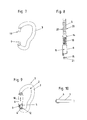
- Fig. 7 shows a side view of the in this form rudimentary C-shaped bracket 3 with its arranged at one end end pin 19 and its arranged at the opposite end pivot joint part.
- Fig. 8 shows in an exploded view and partially in a longitudinal section, the closing part 5, the fixed to the locking member 6 also shown upper support shoulder 14, the elastic return element 10, and the lower support shoulder 15, which fixes by means of the fastening groove 20 and the clamping ring 21 on the closing part 5 becomes.
- the second embodiment according to the Fig. 9 to 18 differs essentially only in the embodiment of the closing part 5 and the locking part 6 of the first embodiment. In the following, only the differences from the first embodiment will be discussed. With regard to all other features and in particular the function according to the invention of the locking part pivot joint 7, reference is made to the previous statements on the first embodiment.
- the Fig. 1 to 7 of the first embodiment find their respective correspondence in the Fig. 9 to 15 of the second embodiment.
- the closing part 5 of the second embodiment is constructed in two parts, as shown particularly well in the exploded views according to FIGS. 16 and 17 you can see.
- Fig. 16 it is an exploded perspective view.
- Fig. 17 shows a longitudinal section in an exploded view.
- Fig. 18 shows in plan view the section along the cutting plane EE Fig. 17 ,
- the in the FIGS. 16 and 17 shown at the top part of the closing part 5 is shown in this embodiment as a sheet metal part.
- the locking member 6 is also in this embodiment as a sliding sleeve, which is slidably mounted in the longitudinal direction 18 on the closing part 5, out.
- the locking member 6 also serves in this embodiment still as a stabilization sleeve for the closing part 5.
- the closing part 5 is at least partially formed as a sheet metal bent part and the sheet metal bending part is embraced by the locking member 6 for its stabilization.
- a projection 17 which is the upper support shoulder 14 for the elastic return element 10.
- the lower support shoulder 15 is located in this embodiment at the lower part of the closing part 5. This is both particularly well in the L jossmalexplosionsdarwolf according to Fig. 17 to see.
- the elastic restoring element 10, which is likewise designed as a spring, is also arranged between the closing part 5 and the blocking part 6 in this exemplary embodiment and also acts between these two components. Also, this embodiment comes with a single elastic return element 10 for biasing both the closing part 5 in the direction of its closed position and the locking member 6 in the direction of its locking position.
- the upper end 16 serves in this embodiment only as stabilization for the above-mentioned bent sheet metal part and is therefore preferably made of metal. This makes it possible to form the remaining locking part 6 of a less stable material such as plastic.
- the operation of the locking member 6 and in particular the Sperrteilschwenkgelenks 7 of this second embodiment corresponds to the operation, as has been described in the first embodiment and therefore need not be explained again here.
Landscapes
- Engineering & Computer Science (AREA)
- General Engineering & Computer Science (AREA)
- Mechanical Engineering (AREA)
- Hooks, Suction Cups, And Attachment By Adhesive Means (AREA)
Abstract
Description
- Die vorliegende Erfindung betrifft einen Karabinerhaken mit einem, zumindest eine Aufnahmeöffnung teilweise umschließenden Bügel und zumindest einem, am Bügel um ein Schließteilschwenkgelenk schwenkbar angeordnetes Schließteil zum Verschließen der Aufnahmeöffnung des Bügels in der Schließstellung des Schließteils, wobei die Aufnahmeöffnung in zumindest einer Offenstellung des Schließteils von außen zugänglich ist und der Karabinerhaken zusätzlich ein, verschiebbar auf oder an dem Schließteil gelagertes Sperrteil zum Arretieren des Schließteils in seiner Schließstellung aufweist.
- Karabinerhaken sind in unterschiedlichsten Ausgestaltungsformen bekannt und werden auch in unterschiedlichsten Einsatzgebieten verwendet. Unter anderem sind hier der Bergsport, der Flugsport und auch die Arbeitssicherheit zu nennen. Oft ist es aus Sicherheitsgründen wichtig, dass das Schließteil nicht versehentlich aus seiner Schließstellung in eine seiner Offenstellungen geschwenkt werden kann. Hierzu gibt es beim Stand der Technik unterschiedliche Lösungen mit verschiedenartig ausgebildeten Sperrteilen, welche dazu dienen, das Schließteil in seiner Schließstellung zu arretieren. Gattungsgemäße Lösungen, wie sie, um ein Beispiel zu nennen, in der
DE 296 10 293 U1 gezeigt sind, sind weit verbreitet. Bei dieser Lösung ist ein Sperrteil verschiebbar auf dem Schließteil angeordnet. Das Sperrteil hält in seiner Arretierstellung das Schließteils in dessen Schließstellung und verhindert dadurch ein Verschwenken des Schließteils in eine seiner Offenstellungen. - Aufgabe der Erfindung ist es, gattungsgemäße Karabinerhaken weiterzuentwickeln.
- In diesem Zusammenhang ist gemäß der Erfindung vorgesehen, dass das Sperrteil zumindest in einer ersten Betriebsstellung mittels eines Sperrteilschwenkgelenks am Bügel schwenkbar gehalten ist.
- Ein wesentlicher Gedanke der Erfindung ist es somit, zusätzlich zum Schließteilschwenkgelenk ein zweites Gelenk in Form des Sperrteilschwenkgelenks vorzusehen, mittels dem das Sperrteil in zumindest einer ersten Betriebsstellung schwenkbar am Bügel gehalten werden kann. Hierdurch können vor allem zwei Vorteile erreicht werden.
- Zum Einen kann das Sperrteilschwenkgelenk dazu verwendet werden, das Sperrteil automatisch beim Betätigen des Schließteils auf diesem zu verschieben und/oder in einer zurückgeschobenen Stellung halten, wenn sich das Schließteil in einer Offenstellung befindet. Zum Anderen können erfindungsgemäße Ausgestaltungsformen aber auch dazu genutzt werden, um die benötigte Anzahl der elastischen Rückstellelemente zu reduzieren. So ist es z.B. möglich, dass der Karabinerhaken nur genau ein elastisches Rückstellelement zur Vorspannung des Schließteils in Richtung hin zu seiner Schließstellung und zur Vorspannung des Sperrteils in Richtung hin zu seiner Arretierstellung, in der das Sperrteil das Schließteil arretiert, aufweist. Bei diesen Ausgestaltungsformen spannt das elastische Rückstellelement somit sowohl das Schließteil als auch das Sperrteil vor. Auf separate Rückstellelemente für Schließteil und Sperrteil kann in diesen Ausgestaltungsformen verzichtet werden. Es ist aber auch darauf hinzuweisen, dass erfindungsgemäße Karabinerhaken auch mit je zumindest einem elastischen Rückstellelement für Schließteil und Sperrteil ausgerüstet sein können.
- Besonders bevorzugte Ausgestaltungsformen der Erfindung sehen vor, dass das Sperrteilschwenkgelenk zumindest ein erstes, fix am Sperrteil angeordnetes Sperrteilschwenkgelenkteil und zumindest ein weiteres, fix am Bügel angeordnetes Sperrteilschwenkgelenkteil aufweist, wobei die Sperrteilschwenkgelenkteile in der ersten Betriebsstellung zur Ausbildung des Sperrteilschwenkgelenks schwenkbar aneinander gelagert sind und in zumindest einer weiteren Betriebsstellung, insbesondere in der Schließstellung des Schließteils, voneinander getrennt sind. Bei diesen Ausgestaltungsformen sind also auch Betriebsstellungen vorgesehen, bei denen die Sperrteilschwenkgelenkteile voneinander getrennt sind und das Sperrteil somit nicht mittels des Sperrteilschwenkgelenks am Bügel gehalten ist. So kann insbesondere vorgesehen sein, dass das Sperrteil, wenn es das Schließteil in der Schließstellung arretieren soll, nicht am Bügel schwenkbar gehalten ist. Hierdurch wird sichergestellt, dass der Benutzer des Karabinerhakens das Sperrteil zum Endarretieren des Schließteils zunächst bewusst betätigen muss und erst anschließend, wenn die Sperrteilschwenkgelenkteile ineinander greifen und schwenkbar aneinander gelagert sind, das Sperrteil automatisch zusammen mit dem Schließteil bewegt bzw. in geöffneter Stellung, in der es das Schließteil nicht arretiert, gehalten wird.
- Besonders bevorzugte Ausgestaltungsformen der Erfindung sehen in diesem Zusammenhang vor, dass das Sperrteilschwenkgelenk zumindest ein erstes, fix am Sperrteil angeordnetes Sperrteilschwenkgelenkteil und zumindest ein weiteres, fix am Bügel angeordnetes Sperrteilschwenkgelenkteil aufweist, wobei eines der Sperrteilschwenkgelenkteile ein Achsbolzen und das andere der Sperrteilschwenkgelenkteile ein Achsbolzenlager zur drehbaren Lagerung des Achsbolzens aufweist oder ist.
- In bevorzugten Ausgestaltungsformen ist das Sperrteil eine das Schließteil zumindest bereichsweise, vorzugsweise vollständig, umfassende Schiebehülse. In solchen Ausgestaltungsformen ist es günstig, wenn die Schiebehülse in der Schließstellung des Schließteils zur Arretierung des Schließteils auch ein Ende, vorzugsweise einen Endzapfen, des Bügels umfasst. Insbesondere in diesen Ausgestaltungsformen kann das Sperrteil zusätzlich zum Arretieren des Schließteils in seiner Schließstellung auch dazu verwendet werden, das Schließteil insgesamt zu stabilisieren.
- Im Sinne einer kompakten nach außen hin möglichst geschlossenen Bauweise des Karabinerhakens sehen bevorzugte Ausgestaltungsformen der Erfindung vor, dass das, vorzugsweise als Schraubenfeder ausgebildete, elastische Rückstellelement in einem Innenraum des Sperrteils und/oder des Schließteils angeordnet ist. Das insbesondere als Schraubenfeder ausgebildete elastische Rückstellelement kann räumlich zwischen Sperrteil und Schließteil angeordnet sein und/oder auf Sperrteil und Schließteil einwirken. Besonders bevorzugte Ausgestaltungsformen sehen vor, dass das elastische Rückstellelement zwischen Sperrteil und Schließteil eingespannt ist. Das Schließteilschwenkgelenk weist günstigerweise eine permanent fix bzw. fest am Bügel angeordnete Schließteilschwenkgelenkachse auf, um die das Schließteil zwischen seiner Schließstellung und seiner Offenstellungen hin und her schwenkbar ist. Besonders bevorzugte Ausgestaltungsformen der Erfindung sehen vor, dass das Schließteil um eine Schließteilschwenkgelenkachse schwenkbar ist und das Sperrteil um eine Sperrteilschwenkgelenkachse schwenkbar ist und die Schließteilschwenkgelenkachse und die Sperrteilschwenkgelenkachse in zumindest einer Betriebsstellung, vorzugsweise in allen Betriebsstellungen, voneinander distanziert angeordnet sind. Die Sperrteilschwenkgelenkachse ist in diesen Ausgestaltungsformen mit anderen Worten somit exzentrisch bezüglich der Schließteilschwenkgelenkachse angeordnet. Besonders bevorzugte Ausgestaltungsformen sehen in diesem Zusammenhang vor, dass die Sperrteilschwenkgelenkachse auf einer von der Aufnahmeöffnung abgewandten Seite der Schließteilschwenkgelenkachse angeordnet ist. Der Vollständigkeit halber wird darauf hingewiesen, dass unter einer distanzierten Anordnung eine Anordnung mit einem Abstand größer Null verstanden wird.
- Weitere Merkmale und Einzelheiten bevorzugter Ausgestaltungsformen der Erfindung werden anhand der nachfolgenden Figurenbeschreibung erläutert. In dieser zeigen:
-
Fig. 1 bis 8 verschiedene Darstellungen zu einem ersten Ausführungsbeispiel der Erfindung; -
Fig. 9 bis 18 verschiedene Darstellungen zu einem zweiten erfindungsgemäßen Ausführungsbeispiel eines Karabinerhakens. - In
Fig. 1 ist der erfindungsgemäße Karabinerhaken 1 des ersten Ausführungsbeispiels in einer perspektivischen Darstellung abgebildet. Zu sehen ist der Bügel 3, an welchem mittels des Schließteilschwenkgelenks 4 das Schließteil 5 um die Schließteilschwenkgelenkachse 12 schwenkbar gelagert ist. InFig. 1 befindet sich das Schließteil 5 in seiner Schließstellung, in der es gemeinsam mit dem Bügel 3 die Aufnahmeöffnung 2 umfangsgeschlossen umfasst. Um eine Schlaufe, ein Seil oder dergleichen in die Aufnahmeöffnung 2 einführen zu können, muss das Schließteil 5 in eine seiner Offenstellungen um die Schließteilschwenkgelenkachse 12 herumgeschwenkt werden. Hierzu muss zunächst vom Bediener des Karabinerhakens 1 das hier als Schiebehülse ausgebildete Sperrteil 6 aus seiner Arretierstellung gemäßFig. 1 verschoben werden. Das Sperrteil 6 ist hierzu verschiebbar auf oder an dem Schließteil 5 gelagert, bzw. in anderen Worten in den Längsrichtungen 18 des Schließteils 5 an oder auf diesem verschiebbar gelagert. In der Arretierstellung gemäßFig. 1 und 3 arretiert bzw. blockiert das Sperrteil 6 das Schließteil 5 in seiner Schließstellung und verhindert somit ein ungewolltes Aufschwenken des Schließteils 5 in eine seiner Offenstellungen. -
Fig. 2 zeigt eine Draufsicht von oben auf den Karabinerhaken 1 gemäßFig. 1. Fig. 3 zeigt eine Seitenansicht auf den Karabinerhaken 1, wobei das Sperrteil 6 geschnitten dargestellt ist. InFig. 3 befindet sich das Sperrteil 6 in seiner Arretierstellung, in der es das Schließteil 5 in dessen Schließstellung hält. InFig. 5 handelt es sich um eine analoge Darstellung, allerdings befindet sich das Schließteil 5 hier in seiner maximal geöffneten Stellung. Das Sperrteil 6 wird inFig. 5 vom Sperrteilschwenkgelenk 7 in einer zurückgezogenen Position gehalten. - Wie insbesondere in den
Fig. 3 und 5 zu sehen, wirkt ein elastisches Rückstellelement 10, hier in Form einer Schraubenfeder, in diesem Ausführungsbeispiel sowohl auf das Sperrteil 6 als auch auf das Schließteil 5 ein. Es ist zwischen einer oberen Stützschulter 14 und einer unteren Stützschulter 15 eingespannt. Die obere Stützschulter 14 ist mit dem Sperrteil 6 fix verbunden. Die untere Stützschulter 15 ist fix am Schließteil 5 befestigt. Durch diese hier beispielhaft gezeigte Ausgestaltungsform wird erreicht, dass der gesamte Karabinerhaken 1 mit nur einem einzigen elastischen Rückstellelement 10 zur Vorspannung bzw. Rückstellung des Schließteils 5 in seine Schließstellung gemäßFig. 1 und 3 und zur Vorspannung bzw. Rückstellung des Schließteils 6 in Richtung hin zu seiner Arretierstellung gemäßFig. 1 und 3 auskommt. - Im ersten Ausführungsbeispiel ist das elastische Rückstellelement 10 um das Schließteil 5 herumgeführt und in einem Innenraum 11 des Sperrteils 6 angeordnet.
- Erfindungsgemäß ist das Sperrteil 6 zumindest in einer ersten Betriebsstellung, hier beispielhaft die Betriebsstellung gemäß
Fig. 5 , mittels des Sperrteilschwenkgelenks 7 am Bügel 3 schwenkbar gehalten. Das Sperrteilschwenkgelenk 7 wird im gezeigten Ausführungsbeispiel durch ein erstes Sperrteilschwenkgelenkteil in Form eines Achsbolzens 8 und eines weiteren Sperrteilschwenkgelenkteils 9 in Form eines Achsbolzenlagers zur drehbaren Lagerung des Achsbolzens gebildet. Im gezeigten Ausführungsbeispiel gemäß derFig. 1 bis 8 ist das erste Sperrteilschwenkgelenkteil 8 in Form des Achsbolzens am Sperrteil 6 fixiert. Das weitere Sperrteilschwenkgelenkteil 9 in Form des Achsbolzenlagers ist in diesem Ausführungsbeispiel am Bügel 3 fix angeordnet. Dies muss aber nicht so sein, eine umgekehrte Ausgestaltungsform ist, um ein Beispiel zu nennen, auch möglich. Bei einer solchen kann das Sperrteilschwenkgelenkteil 8 in Form des Achsbolzens auch am Bügel 3 und das weitere Sperrteilschwenkgelenkteil 9 in Form des Achsbolzenlagers auch am Sperrteil 6 angeordnet sein. -
Fig. 4 zeigt den Bereich A ausFig. 3 vergrößert.Fig. 6 zeigt den Bereich B ausFig. 5 vergrößert. Besonders wenn man dieFig. 4 und 6 miteinander vergleicht, ist zu sehen, dass bei diesem Ausführungsbeispiel die beiden Sperrteilschwenkgelenkteile 8 und 9 nicht permanent miteinander in Eingriff stehen, sondern das Sperrteilschwenkgelenk 7 nur in bestimmten Betriebsstellungen als Gelenk wirkt. In der Schließstellung des Schließteils 5 gemäß derFig. 1, 3 und 4 greifen die beiden Sperrteilschwenkgelenkteile 8 und 9 nicht ineinander ein, in der Offenstellung des Schließteils 5 gemäßFig. 5 und 6 schon. - Will nun der Benutzer des Karabinerhakens 1 das Schließteil 5 aus seiner in den
Fig. 1 und 3 dargestellten Schließstellung in eine Offenstellung schwenken, so muss er zunächst die Arretierung mittels des Sperrteils 6 lösen. Hierzu muss er von Hand das Sperrteil 6 auf dem Schließteil 5 in Richtung hin zum Schließteilschwenkgelenk 4 schieben und zwar so weit, bis das Sperrteil 6 so weit zurückgeschoben ist, dass es den Endzapfen 19 des Bügels 3 freigibt. Erst ab dieser Stellung kann das Schließteil 5 aus seiner Schließstellung herausgeschwenkt werden. Ist das Sperrteil 6 so weit nach hinten geschoben, dass es den Endzapfen 19 des Bügels 3 freigibt, so kommt beim Verschwenken des Schließteils 5 in Richtung hin zu seiner maximalen Offenstellung gemäßFig. 5 das erste Sperrteilschwenkgelenkteil 8 in Form des Achsbolzens automatisch in Eingriff mit dem weiteren Sperrteilschwenkgelenkteil 9 in Form des Achsbolzenlagers, sodass ab dieser Betriebsstellung das Sperrteilschwenkgelenk 7 als solches ausgebildet ist und wirkt. Beim weiteren Verschwenken des Schließteils 5 in Richtung hin zu seiner maximalen Offenstellung gemäßFig. 5 hält das Sperrteilschwenkgelenk 7 dann das Sperrteil 6 automatisch in einer zurückgezogenen Stellung bzw. zieht dies noch weiter nach hinten in Richtung des Schließteilschwenkgelenks 4. Der Vollständigkeit halber wird darauf hingewiesen, dass das Schließteil 5 natürlich nicht immer in seine maximal geöffnete Stellung gemäßFig. 5 geschwenkt werden muss. - Lässt der Benutzer des Karabinerhakens 1 nun in einer Offenstellung das Schließteil 5 und das Sperrteil 6 los, so sorgt das unter Spannung stehende elastische Rückstellelement 10 sowohl für die Rückstellung des Schließteils 5 in seine Schließstellung als auch des Sperrteils 6 in seine Arretierungsstellung. Bei dieser Rückbewegung hält das Sperrteilschwenkgelenk 7 das Sperrteil 6 so lange zurück, so lange die beiden Sperrteilschwenkgelenkteile 8 und 9 ineinander in Eingriff stehen. Dies ermöglicht es, dass das Schließteil 5 zuerst in seine Schließstellung zurückfindet, bevor das erste Sperrteilschwenkgelenkteil 8 vom weiteren Sperrteilschwenkgelenkteil 9 freigegeben wird und das Sperrteil 6 vom elastischen Rückstellelement 10 in seine Arretierstellung gemäß
Fig. 3 , in der es das Schließteil 5 wieder in seiner Schließstellung arretiert, zurückgeschoben wird. - Insbesondere in den
Fig. 5 und 6 ist gut zu sehen, dass die Schließteilschwenkgelenkachse 12 und die Sperrteilschwenkgelenkachse 13 voneinander distanziert angeordnet sind. Besonders bevorzugt ist dabei, wie eingangs bereits erläutert, vorgesehen, dass die Sperrteilschwenkgelenkachse 13 auf einer von der Aufnahmeöffnung 2 abgewandten Seite der Schließteilschwenkgelenkachse 12 angeordnet ist. -
Fig. 7 zeigt in einer Seitenansicht den in dieser Form ansatzweise C-förmig gebogenen Bügel 3 mit seinem an einem Ende angeordneten Endzapfen 19 und seinem am gegenüberliegenden Ende angeordneten Schwenkgelenkteil 9.Fig. 8 zeigt in einer Explosionsdarstellung und teilweise in einem Längsschnitt das Schließteil 5, die fix am ebenfalls dargestellten Sperrteil 6 zu befestigende obere Stützschulter 14, das elastische Rückstellelement 10, sowie die untere Stützschulter 15, welche mittels der Befestigungsnut 20 und dem Klemmring 21 am Schließteil 5 fixiert wird. - Das zweite Ausführungsbeispiel gemäß der
Fig. 9 bis 18 unterscheidet sich im Wesentlichen nur in der Ausgestaltung des Schließteils 5 und des Sperrteils 6 vom ersten Ausführungsbeispiel. Im Folgenden wird nur noch auf die Unterschiede zum ersten Ausführungsbeispiel eingegangen. Bezüglich aller anderen Merkmale und insbesondere der erfindungsgemäßen Funktion des Sperrteilschwenkgelenks 7 wird auf die bisherigen Ausführungen zum ersten Ausführungsbeispiel verwiesen. DieFig. 1 bis 7 des ersten Ausführungsbeispiels finden ihre jeweilige Entsprechung in denFig. 9 bis 15 des zweiten Ausführungsbeispiels. - Anstelle des in dem ersten Ausführungsbeispiel massiv und einstückig ausgebildeten Schließteils 5 ist das Schließteil 5 des zweiten Ausführungsbeispiels zweiteilig aufgebaut, wie dies besonders gut in den Explosionsdarstellungen gemäß
Fig. 16 und 17 zu sehen ist. InFig. 16 handelt es sich um eine perspektivische Explosionsdarstellung.Fig. 17 zeigt einen Längsschnitt als Explosionsdarstellung.Fig. 18 zeigt in Draufsicht den Schnitt entlang der Schnittebene EE ausFig. 17 . - Der in den
Fig. 16 und 17 ganz oben gezeigte Teil des Schließteils 5 ist in diesem Ausführungsbeispiel als Blechbiegeteil gezeigt. In dieses Blechbiegeteil kann der zweite Teil des Schließteils 5, welcher in denFig. 16 und 17 jeweils unten dargestellt ist, eingeschoben und mittels der Befestigungslöcher 22 fixiert werden. Das Sperrteil 6 ist in diesem Ausführungsbeispiel ebenfalls als eine Schiebehülse, welche in Längsrichtung 18 auf dem Schließteil 5 verschiebbar gelagert ist, geführt. Zusätzlich zu seiner Arretierungsfunktion dient das Sperrteil 6 in dieser Ausgestaltungsform auch noch als eine Stabilisierungsmanschette für das Schließteil 5. In diesem Sinne kann somit vorgesehen sein, dass das Schließteil 5 zumindest bereichsweise als Blechbiegeteil ausgebildet ist und das Blechbiegeteil zu seiner Stabilisierung vom Sperrteil 6 umgriffen ist. Im Inneren 11 des Sperrteils 6 dieses zweiten Ausführungsbeispiels befindet sich ein Vorsprung 17, welcher die obere Stützschulter 14 für das elastische Rückstellelement 10 darstellt. Die untere Stützschulter 15 befindet sich in diesem Ausführungsbeispiel am unteren Teil des Schließteils 5. Dies ist beides besonders gut in der Längsschnittexplosionsdarstellung gemäßFig. 17 zu sehen. Das hier ebenfalls als Feder ausgebildete elastische Rückstellelement 10 ist auch in diesem Ausführungsbeispiel zwischen dem Schließteil 5 und dem Sperrteil 6 angeordnet und wirkt auch zwischen diesen beiden Bauteilen. Auch dieses Ausführungsbeispiel kommt mit einem einzigen elastischen Rückstellelement 10 zur Vorspannung sowohl des Schließteils 5 in Richtung hin zu seiner Schließstellung als auch des Sperrteils 6 in Richtung hin zu seiner Arretierungsstellung aus. Der obere Abschluss 16 dient in diesem Ausführungsbeispiel lediglich als Stabilisierungstell für das oben genannte Blechbiegeteil und ist daher vorzugsweise aus Metall hergestellt. Dies ermöglicht es, das restliche Sperrteil 6 aus einem weniger stabilen Werkstoff wie z.B. Kunststoff auszubilden. Die Funktionsweise des Sperrteils 6 und insbesondere des Sperrteilschwenkgelenks 7 dieses zweiten Ausführungsbeispiels entspricht der Wirkungsweise, wie sie beim ersten Ausführungsbeispiel geschildert worden ist und muss hier daher nicht noch einmal erläutert werden. -
- 1
- Karabinerhaken
- 2
- Aufnahmeöffnung
- 3
- Bügel
- 4
- Schließteilschwenkgelenk
- 5
- Schließteil
- 6
- Sperrteil
- 7
- Sperrteilschwenkgelenk
- 8
- erstes Sperrteilschwenkgelenkteil
- 9
- zweites Sperrteilschwenkgelenkteil
- 10
- elastisches Rückstellelement
- 11
- Innenraum
- 12
- Schließteilschwenkgelenkachse
- 13
- Sperrteilschwenkgelenkachse
- 14
- obere Stützschulter
- 15
- untere Stützschulter
- 16
- oberer Abschluss
- 17
- Vorsprung
- 18
- Längsrichtung
- 19
- Endzapfen
- 20
- Befestigungsnut
- 21
- Klemmring
- 22
- Befestigungslöcher
Claims (10)
- Karabinerhaken (1) mit einem, zumindest eine Aufnahmeöffnung (2) teilweise umschließenden Bügel (3) und zumindest einem, am Bügel (3) um ein Schließteilschwenkgelenk (4) schwenkbar angeordnetes Schließteil (5) zum Verschließen der Aufnahmeöffnung (2) des Bügels (3) in der Schließstellung des Schließteils (5), wobei die Aufnahmeöffnung (2) in zumindest einer Offenstellung des Schließteils (5) von außen zugänglich ist und der Karabinerhaken (1) zusätzlich ein, verschiebbar auf oder an dem Schließteil (5) gelagertes Sperrteil (6) zum Arretieren des Schließteils (5) in seiner Schließstellung aufweist, dadurch gekennzeichnet, dass das Sperrteil (6) zumindest in einer ersten Betriebsstellung mittels eines Sperrteilschwenkgelenks (7) am Bügel (3) schwenkbar gehalten ist.
- Karabinerhaken (1) nach Anspruch 1, dadurch gekennzeichnet, dass das Sperrteilschwenkgelenk (7) zumindest ein erstes, fix am Sperrteil (6) angeordnetes Sperrteilschwenkgelenkteil (8) und zumindest ein weiteres, fix am Bügel (3) angeordnetes Sperrteilschwenkgelenkteil (9) aufweist, wobei die Sperrteilschwenkgelenkteile (8, 9) in der ersten Betriebsstellung zur Ausbildung des Sperrteilschwenkgelenks (7) schwenkbar aneinander gelagert sind und in zumindest einer weiteren Betriebsstellung, insbesondere in der Schließstellung des Schließteils (5), voneinander getrennt sind.
- Karabinerhaken (1) nach Anspruch 1 oder 2, dadurch gekennzeichnet, dass das Sperrteilschwenkgelenk (7) zumindest ein erstes, fix am Sperrteil (6) angeordnetes Sperrteilschwenkgelenkteil (8) und zumindest ein weiteres, fix am Bügel (3) angeordnetes Sperrteilschwenkgelenkteil (9) aufweist, wobei eines der Sperrteilschwenkgelenkteile (8, 9) ein Achsbolzen und das andere der Sperrteilschwenkgelenkteile (8, 9) ein Achsbolzenlager zur drehbaren Lagerung des Achsbolzens aufweist oder ist.
- Karabinerhaken (1) nach einem der Ansprüche 1 bis 3, dadurch gekennzeichnet, dass das Sperrteil (6) eine, das Schließteil (5) zumindest bereichsweise, vorzugsweise vollständig, umfassende Schiebehülse ist, und/oder dass das Schließteil (5) zumindest bereichsweise als Blechbiegeteil ausgebildet ist und das Blechbiegeteil zu seiner Stabilisierung vom Sperrteil (6) umgriffen ist.
- Karabinerhaken (1) nach einem der Ansprüche 1 bis 4, dadurch gekennzeichnet, dass der Karabinerhaken (1) zumindest ein, vorzugsweise genau ein, elastisches Rückstellelement (10) zur Vorspannung des Schließteils (5) in Richtung hin zu seiner Schließstellung und/oder zur Vorspannung des Sperrteils (6) in Richtung hin zu seiner Arretierstellung, in der das Sperrteil (6) das Schließteil (5) arretiert, aufweist.
- Karabinerhaken (1) nach Anspruch 5, dadurch gekennzeichnet, dass das, vorzugsweise als Schraubenfeder ausgebildete, elastische Rückstellelement (10) in einem Innenraum (11) des Sperrteils (6) und/oder des Schließteils (5) angeordnet ist.
- Karabinerhaken (1) nach Anspruch 5 oder 6, dadurch gekennzeichnet, dass das, vorzugsweise als Schraubenfeder ausgebildete, elastische Rückstellelement (10) zwischen Sperrteil (6) und Schließteil (5) angeordnet ist und/oder auf Sperrteil (6) und Schließteil (5) einwirkt.
- Karabinerhaken (1) nach einem der Ansprüche 1 bis 7, dadurch gekennzeichnet, dass das Schließteilschwenkgelenk (4) eine permanent am Bügel (3) feste Schließteilschwenkgelenkachse (12) aufweist, um die das Schließteil (5) schwenkbar ist.
- Karabinerhaken (1) nach einem der Ansprüche 1 bis 8, dadurch gekennzeichnet, dass das Schließteil (5) um eine Schließteilschwenkgelenkachse (12) schwenkbar ist und das Sperrteil (6) um eine Sperrteilschwenkgelenkachse (13) schwenkbar ist und die Schließteilschwenkgelenkachse (12) und die Sperrteilschwenkgelenkachse (13) in zumindest einer Betriebsstellung, vorzugsweise in allen Betriebsstellungen, voneinander distanziert angeordnet sind.
- Karabinerhaken (1) nach Anspruch 9, dadurch gekennzeichnet, dass die Sperrteilschwenkgelenkachse (13) auf einer von der Aufnahmeöffnung (2) abgewandten Seite der Schließteilschwenkgelenkachse (12) angeordnet ist.
Applications Claiming Priority (1)
| Application Number | Priority Date | Filing Date | Title |
|---|---|---|---|
| ATA921/2011A AT511336B1 (de) | 2011-06-24 | 2011-06-24 | Karabinerhaken |
Publications (3)
| Publication Number | Publication Date |
|---|---|
| EP2538094A2 true EP2538094A2 (de) | 2012-12-26 |
| EP2538094A3 EP2538094A3 (de) | 2013-01-16 |
| EP2538094B1 EP2538094B1 (de) | 2014-11-19 |
Family
ID=46331010
Family Applications (1)
| Application Number | Title | Priority Date | Filing Date |
|---|---|---|---|
| EP12004559.6A Active EP2538094B1 (de) | 2011-06-24 | 2012-06-18 | Karabinerhaken |
Country Status (3)
| Country | Link |
|---|---|
| EP (1) | EP2538094B1 (de) |
| AT (1) | AT511336B1 (de) |
| ES (1) | ES2530359T3 (de) |
Cited By (1)
| Publication number | Priority date | Publication date | Assignee | Title |
|---|---|---|---|---|
| CN116788939A (zh) * | 2022-12-26 | 2023-09-22 | 久维科技(苏州)有限公司 | 一种悬挂组件 |
Citations (1)
| Publication number | Priority date | Publication date | Assignee | Title |
|---|---|---|---|---|
| DE29610293U1 (de) | 1996-06-12 | 1996-10-24 | Kong Deutschland GmbH, 85551 Kirchheim | Karabinerhaken |
Family Cites Families (7)
| Publication number | Priority date | Publication date | Assignee | Title |
|---|---|---|---|---|
| DE9102003U1 (de) * | 1991-02-20 | 1991-05-08 | "Stubai" Werkzeugindustrie Registrierte Genossenschaft Mbh, Fulpmes | Karabinerhaken |
| EP0739455A1 (de) * | 1994-01-14 | 1996-10-30 | Stubai- Werkzeugindustrie Registrierte Genossenschaft Mit Beschränkter Haftung | Karabinerhaken |
| US6588076B1 (en) * | 2002-04-08 | 2003-07-08 | Gary E. Choate | Carabiner with locking gate |
| US7228601B2 (en) * | 2004-01-27 | 2007-06-12 | Techxotic Lc | Carabiners having a captive eye opening |
| US20080104810A1 (en) * | 2006-11-07 | 2008-05-08 | Feng Chia Liang | Snap hook with slidable lock |
| AT11210U1 (de) * | 2008-11-27 | 2010-06-15 | Aba Hoertnagl Kg Werkzeuge Vor | Karabinerhaken |
| US8474112B2 (en) * | 2009-07-29 | 2013-07-02 | Rock Exotica Llc | Carabiners with multi mode locking sleeves, methods of manufacturing such carabiners, and methods of using such carabiners |
-
2011
- 2011-06-24 AT ATA921/2011A patent/AT511336B1/de active
-
2012
- 2012-06-18 EP EP12004559.6A patent/EP2538094B1/de active Active
- 2012-06-18 ES ES12004559T patent/ES2530359T3/es active Active
Patent Citations (1)
| Publication number | Priority date | Publication date | Assignee | Title |
|---|---|---|---|---|
| DE29610293U1 (de) | 1996-06-12 | 1996-10-24 | Kong Deutschland GmbH, 85551 Kirchheim | Karabinerhaken |
Cited By (1)
| Publication number | Priority date | Publication date | Assignee | Title |
|---|---|---|---|---|
| CN116788939A (zh) * | 2022-12-26 | 2023-09-22 | 久维科技(苏州)有限公司 | 一种悬挂组件 |
Also Published As
| Publication number | Publication date |
|---|---|
| ES2530359T3 (es) | 2015-03-02 |
| AT511336B1 (de) | 2012-11-15 |
| EP2538094B1 (de) | 2014-11-19 |
| AT511336A4 (de) | 2012-11-15 |
| EP2538094A3 (de) | 2013-01-16 |
Similar Documents
| Publication | Publication Date | Title |
|---|---|---|
| EP3658336B1 (de) | Hakenhalterung für eine werkzeugmaschine | |
| DE29516306U1 (de) | Schließvorrichtung für Behälter, wie Koffer, Taschen o.dgl. | |
| EP4019789B1 (de) | Möbelbeschlag | |
| EP2792288B1 (de) | Rastvorrichtung für ein Staubsauger-Saugrohr | |
| DE60017190T2 (de) | Fahrzeugmontierter gepäckträger | |
| DE60100384T2 (de) | Messer | |
| WO2018033221A1 (de) | Möbelscharnier | |
| EP3266651B1 (de) | Vorrichtung zum sichern von ladegut | |
| DE2614961B2 (de) | Karabinerhaken, insbesondere zum Transport von schweren Außenlasten an Hubschraubern | |
| DE3151019C2 (de) | Vorrichtung zum Befestigen des oberen Umlenkbeschlages für einen Dreipunktsicherheitsgurt an der Karosserie eines Kraftfahrzeuges | |
| AT510061B1 (de) | Karabinerhaken | |
| DE102022114415A1 (de) | Messer | |
| EP2538094B1 (de) | Karabinerhaken | |
| DE1653947C3 (de) | Verbindungshebel zwischen dem Haspenoberteil und Haspenunterteil eines Haspenschlosses | |
| DE102018000211A1 (de) | Magnetschlossvorrichtung zum Verschließen eines einen Behältnisabschnitt und ein Deckelteil aufweisenden Behältnisses | |
| DE3502069C2 (de) | ||
| AT514167B1 (de) | Verriegelungseinrichtung | |
| EP4491357A1 (de) | Messer | |
| DE202013002202U1 (de) | Behälterverschluss | |
| DE102010025978A1 (de) | Stativkopf-Anordnung | |
| DE102009051594B4 (de) | Haken, insbesondere für Sicherheitseinrichtungen | |
| DE2363445C3 (de) | Gartenschere | |
| EP3378822B1 (de) | Hebevorrichtung | |
| DE202010000679U1 (de) | Brecheisen mit schneller Winkelverstellung | |
| EP1932719A1 (de) | Haltevorrichtung für Gepäckstangen |
Legal Events
| Date | Code | Title | Description |
|---|---|---|---|
| PUAL | Search report despatched |
Free format text: ORIGINAL CODE: 0009013 |
|
| PUAI | Public reference made under article 153(3) epc to a published international application that has entered the european phase |
Free format text: ORIGINAL CODE: 0009012 |
|
| AK | Designated contracting states |
Kind code of ref document: A2 Designated state(s): AL AT BE BG CH CY CZ DE DK EE ES FI FR GB GR HR HU IE IS IT LI LT LU LV MC MK MT NL NO PL PT RO RS SE SI SK SM TR |
|
| AX | Request for extension of the european patent |
Extension state: BA ME |
|
| AK | Designated contracting states |
Kind code of ref document: A3 Designated state(s): AL AT BE BG CH CY CZ DE DK EE ES FI FR GB GR HR HU IE IS IT LI LT LU LV MC MK MT NL NO PL PT RO RS SE SI SK SM TR |
|
| AX | Request for extension of the european patent |
Extension state: BA ME |
|
| RIC1 | Information provided on ipc code assigned before grant |
Ipc: F16B 45/02 20060101AFI20121210BHEP |
|
| 17P | Request for examination filed |
Effective date: 20130408 |
|
| GRAP | Despatch of communication of intention to grant a patent |
Free format text: ORIGINAL CODE: EPIDOSNIGR1 |
|
| INTG | Intention to grant announced |
Effective date: 20140819 |
|
| GRAS | Grant fee paid |
Free format text: ORIGINAL CODE: EPIDOSNIGR3 |
|
| GRAA | (expected) grant |
Free format text: ORIGINAL CODE: 0009210 |
|
| AK | Designated contracting states |
Kind code of ref document: B1 Designated state(s): AL AT BE BG CH CY CZ DE DK EE ES FI FR GB GR HR HU IE IS IT LI LT LU LV MC MK MT NL NO PL PT RO RS SE SI SK SM TR |
|
| REG | Reference to a national code |
Ref country code: GB Ref legal event code: FG4D Free format text: NOT ENGLISH |
|
| REG | Reference to a national code |
Ref country code: CH Ref legal event code: EP |
|
| REG | Reference to a national code |
Ref country code: AT Ref legal event code: REF Ref document number: 697205 Country of ref document: AT Kind code of ref document: T Effective date: 20141215 |
|
| REG | Reference to a national code |
Ref country code: IE Ref legal event code: FG4D Free format text: LANGUAGE OF EP DOCUMENT: GERMAN |
|
| REG | Reference to a national code |
Ref country code: DE Ref legal event code: R096 Ref document number: 502012001604 Country of ref document: DE Effective date: 20141231 |
|
| REG | Reference to a national code |
Ref country code: CH Ref legal event code: NV Representative=s name: LUCHS AND PARTNER PATENTANWAELTE, CH |
|
| REG | Reference to a national code |
Ref country code: DE Ref legal event code: R082 Ref document number: 502012001604 Country of ref document: DE Representative=s name: PATENTANWAELTE BEHRMANN WAGNER PARTNERSCHAFTSG, DE |
|
| REG | Reference to a national code |
Ref country code: ES Ref legal event code: FG2A Ref document number: 2530359 Country of ref document: ES Kind code of ref document: T3 Effective date: 20150302 |
|
| REG | Reference to a national code |
Ref country code: NL Ref legal event code: VDEP Effective date: 20141119 |
|
| REG | Reference to a national code |
Ref country code: LT Ref legal event code: MG4D |
|
| PG25 | Lapsed in a contracting state [announced via postgrant information from national office to epo] |
Ref country code: FI Free format text: LAPSE BECAUSE OF FAILURE TO SUBMIT A TRANSLATION OF THE DESCRIPTION OR TO PAY THE FEE WITHIN THE PRESCRIBED TIME-LIMIT Effective date: 20141119 Ref country code: IS Free format text: LAPSE BECAUSE OF FAILURE TO SUBMIT A TRANSLATION OF THE DESCRIPTION OR TO PAY THE FEE WITHIN THE PRESCRIBED TIME-LIMIT Effective date: 20150319 Ref country code: NL Free format text: LAPSE BECAUSE OF FAILURE TO SUBMIT A TRANSLATION OF THE DESCRIPTION OR TO PAY THE FEE WITHIN THE PRESCRIBED TIME-LIMIT Effective date: 20141119 Ref country code: NO Free format text: LAPSE BECAUSE OF FAILURE TO SUBMIT A TRANSLATION OF THE DESCRIPTION OR TO PAY THE FEE WITHIN THE PRESCRIBED TIME-LIMIT Effective date: 20150219 Ref country code: PT Free format text: LAPSE BECAUSE OF FAILURE TO SUBMIT A TRANSLATION OF THE DESCRIPTION OR TO PAY THE FEE WITHIN THE PRESCRIBED TIME-LIMIT Effective date: 20150319 Ref country code: LT Free format text: LAPSE BECAUSE OF FAILURE TO SUBMIT A TRANSLATION OF THE DESCRIPTION OR TO PAY THE FEE WITHIN THE PRESCRIBED TIME-LIMIT Effective date: 20141119 |
|
| PG25 | Lapsed in a contracting state [announced via postgrant information from national office to epo] |
Ref country code: RS Free format text: LAPSE BECAUSE OF FAILURE TO SUBMIT A TRANSLATION OF THE DESCRIPTION OR TO PAY THE FEE WITHIN THE PRESCRIBED TIME-LIMIT Effective date: 20141119 Ref country code: PL Free format text: LAPSE BECAUSE OF FAILURE TO SUBMIT A TRANSLATION OF THE DESCRIPTION OR TO PAY THE FEE WITHIN THE PRESCRIBED TIME-LIMIT Effective date: 20141119 Ref country code: GR Free format text: LAPSE BECAUSE OF FAILURE TO SUBMIT A TRANSLATION OF THE DESCRIPTION OR TO PAY THE FEE WITHIN THE PRESCRIBED TIME-LIMIT Effective date: 20150220 Ref country code: CY Free format text: LAPSE BECAUSE OF FAILURE TO SUBMIT A TRANSLATION OF THE DESCRIPTION OR TO PAY THE FEE WITHIN THE PRESCRIBED TIME-LIMIT Effective date: 20141119 Ref country code: HR Free format text: LAPSE BECAUSE OF FAILURE TO SUBMIT A TRANSLATION OF THE DESCRIPTION OR TO PAY THE FEE WITHIN THE PRESCRIBED TIME-LIMIT Effective date: 20141119 Ref country code: SE Free format text: LAPSE BECAUSE OF FAILURE TO SUBMIT A TRANSLATION OF THE DESCRIPTION OR TO PAY THE FEE WITHIN THE PRESCRIBED TIME-LIMIT Effective date: 20141119 Ref country code: LV Free format text: LAPSE BECAUSE OF FAILURE TO SUBMIT A TRANSLATION OF THE DESCRIPTION OR TO PAY THE FEE WITHIN THE PRESCRIBED TIME-LIMIT Effective date: 20141119 |
|
| REG | Reference to a national code |
Ref country code: SK Ref legal event code: T3 Ref document number: E 18200 Country of ref document: SK |
|
| PG25 | Lapsed in a contracting state [announced via postgrant information from national office to epo] |
Ref country code: DK Free format text: LAPSE BECAUSE OF FAILURE TO SUBMIT A TRANSLATION OF THE DESCRIPTION OR TO PAY THE FEE WITHIN THE PRESCRIBED TIME-LIMIT Effective date: 20141119 Ref country code: EE Free format text: LAPSE BECAUSE OF FAILURE TO SUBMIT A TRANSLATION OF THE DESCRIPTION OR TO PAY THE FEE WITHIN THE PRESCRIBED TIME-LIMIT Effective date: 20141119 Ref country code: RO Free format text: LAPSE BECAUSE OF FAILURE TO SUBMIT A TRANSLATION OF THE DESCRIPTION OR TO PAY THE FEE WITHIN THE PRESCRIBED TIME-LIMIT Effective date: 20141119 |
|
| REG | Reference to a national code |
Ref country code: DE Ref legal event code: R097 Ref document number: 502012001604 Country of ref document: DE |
|
| PLBE | No opposition filed within time limit |
Free format text: ORIGINAL CODE: 0009261 |
|
| STAA | Information on the status of an ep patent application or granted ep patent |
Free format text: STATUS: NO OPPOSITION FILED WITHIN TIME LIMIT |
|
| 26N | No opposition filed |
Effective date: 20150820 |
|
| PG25 | Lapsed in a contracting state [announced via postgrant information from national office to epo] |
Ref country code: MC Free format text: LAPSE BECAUSE OF FAILURE TO SUBMIT A TRANSLATION OF THE DESCRIPTION OR TO PAY THE FEE WITHIN THE PRESCRIBED TIME-LIMIT Effective date: 20141119 |
|
| PG25 | Lapsed in a contracting state [announced via postgrant information from national office to epo] |
Ref country code: LU Free format text: LAPSE BECAUSE OF FAILURE TO SUBMIT A TRANSLATION OF THE DESCRIPTION OR TO PAY THE FEE WITHIN THE PRESCRIBED TIME-LIMIT Effective date: 20150618 Ref country code: SI Free format text: LAPSE BECAUSE OF FAILURE TO SUBMIT A TRANSLATION OF THE DESCRIPTION OR TO PAY THE FEE WITHIN THE PRESCRIBED TIME-LIMIT Effective date: 20141119 |
|
| REG | Reference to a national code |
Ref country code: IE Ref legal event code: MM4A |
|
| PG25 | Lapsed in a contracting state [announced via postgrant information from national office to epo] |
Ref country code: IE Free format text: LAPSE BECAUSE OF NON-PAYMENT OF DUE FEES Effective date: 20150618 |
|
| REG | Reference to a national code |
Ref country code: FR Ref legal event code: PLFP Year of fee payment: 5 |
|
| PG25 | Lapsed in a contracting state [announced via postgrant information from national office to epo] |
Ref country code: MT Free format text: LAPSE BECAUSE OF FAILURE TO SUBMIT A TRANSLATION OF THE DESCRIPTION OR TO PAY THE FEE WITHIN THE PRESCRIBED TIME-LIMIT Effective date: 20141119 |
|
| PG25 | Lapsed in a contracting state [announced via postgrant information from national office to epo] |
Ref country code: BG Free format text: LAPSE BECAUSE OF FAILURE TO SUBMIT A TRANSLATION OF THE DESCRIPTION OR TO PAY THE FEE WITHIN THE PRESCRIBED TIME-LIMIT Effective date: 20141119 Ref country code: SM Free format text: LAPSE BECAUSE OF FAILURE TO SUBMIT A TRANSLATION OF THE DESCRIPTION OR TO PAY THE FEE WITHIN THE PRESCRIBED TIME-LIMIT Effective date: 20141119 Ref country code: HU Free format text: LAPSE BECAUSE OF FAILURE TO SUBMIT A TRANSLATION OF THE DESCRIPTION OR TO PAY THE FEE WITHIN THE PRESCRIBED TIME-LIMIT; INVALID AB INITIO Effective date: 20120618 |
|
| REG | Reference to a national code |
Ref country code: FR Ref legal event code: PLFP Year of fee payment: 6 |
|
| PG25 | Lapsed in a contracting state [announced via postgrant information from national office to epo] |
Ref country code: BE Free format text: LAPSE BECAUSE OF NON-PAYMENT OF DUE FEES Effective date: 20150630 |
|
| PG25 | Lapsed in a contracting state [announced via postgrant information from national office to epo] |
Ref country code: TR Free format text: LAPSE BECAUSE OF FAILURE TO SUBMIT A TRANSLATION OF THE DESCRIPTION OR TO PAY THE FEE WITHIN THE PRESCRIBED TIME-LIMIT Effective date: 20141119 |
|
| REG | Reference to a national code |
Ref country code: FR Ref legal event code: PLFP Year of fee payment: 7 |
|
| PG25 | Lapsed in a contracting state [announced via postgrant information from national office to epo] |
Ref country code: MK Free format text: LAPSE BECAUSE OF FAILURE TO SUBMIT A TRANSLATION OF THE DESCRIPTION OR TO PAY THE FEE WITHIN THE PRESCRIBED TIME-LIMIT Effective date: 20141119 |
|
| REG | Reference to a national code |
Ref country code: AT Ref legal event code: MM01 Ref document number: 697205 Country of ref document: AT Kind code of ref document: T Effective date: 20170618 |
|
| PG25 | Lapsed in a contracting state [announced via postgrant information from national office to epo] |
Ref country code: AL Free format text: LAPSE BECAUSE OF FAILURE TO SUBMIT A TRANSLATION OF THE DESCRIPTION OR TO PAY THE FEE WITHIN THE PRESCRIBED TIME-LIMIT Effective date: 20141119 |
|
| PG25 | Lapsed in a contracting state [announced via postgrant information from national office to epo] |
Ref country code: AT Free format text: LAPSE BECAUSE OF NON-PAYMENT OF DUE FEES Effective date: 20170618 |
|
| PGFP | Annual fee paid to national office [announced via postgrant information from national office to epo] |
Ref country code: DE Payment date: 20250626 Year of fee payment: 14 |
|
| PGFP | Annual fee paid to national office [announced via postgrant information from national office to epo] |
Ref country code: GB Payment date: 20250618 Year of fee payment: 14 |
|
| PGFP | Annual fee paid to national office [announced via postgrant information from national office to epo] |
Ref country code: FR Payment date: 20250624 Year of fee payment: 14 |
|
| PGFP | Annual fee paid to national office [announced via postgrant information from national office to epo] |
Ref country code: SK Payment date: 20250603 Year of fee payment: 14 |
|
| PGFP | Annual fee paid to national office [announced via postgrant information from national office to epo] |
Ref country code: CZ Payment date: 20250603 Year of fee payment: 14 |
|
| PGFP | Annual fee paid to national office [announced via postgrant information from national office to epo] |
Ref country code: ES Payment date: 20250710 Year of fee payment: 14 |
|
| PGFP | Annual fee paid to national office [announced via postgrant information from national office to epo] |
Ref country code: IT Payment date: 20250623 Year of fee payment: 14 |
|
| PGFP | Annual fee paid to national office [announced via postgrant information from national office to epo] |
Ref country code: CH Payment date: 20250701 Year of fee payment: 14 |